Note: Descriptions are shown in the official language in which they were submitted.
2154378
-2-
1 BACKGROUND OF THE INVENTION
2 1. Field of the Invention:
3 The present invention relates in general to measurement-while-
4 drilling systems, and in particular relates to measurement-while-drilling
systems which transmit or receive electromagnetic fields.
6 2. Description of the Prior Art:
7 Measurement-while-drilling systems are now essential
8 components of sophisticated exploration operations, and are utilized to
9 provide real-time data pertaining to drilling conditions as well as the
wellbore
and surrounding formations. In particular, resistivity logs can be developed
11 during drilling operations which, in some cases, provide a full substitute
for
12 the more conventional wireline electric logs. Other types of logging
13 operations are also conducted in measurement-while-drilling systems,
14 including neutron porosity measurements which provide a measure of the
wellbore and formation porosity. The resistivity measurements can be
16 utilized to provide a measure of the formation resistivity, the borehole
17 diameter, the diameter of invasion of drilling mud into the formation, and
to
18 detect formation boundaries and formation changes.
19 In prior art systems, it is conventional to place the transmitting
and receiving antennas of the measurement-while-drilling system within the
21 tubular body of a drill collar or drill pipe member. Most commonly, a
portion
22 of the drill collar or drill pipe is "necked-down" (that is, milled or cut
to a
23 reduced radial dimension), to provide a relatively safe location for
placement
24 of the transmitting and receiving antennas. This, of course, structurally
weakens the drill pipe or drill collar member, and renders it more susceptible
DOCKET NO. 414-4780-US
-3- _ 21~43'~3
1 to mechanical failure during drilling operations. In the prior
art devices, the
2 antennas are placed in or about the exterior surface of the
drill pipe or drill
3 collar member, since the drill pipe or drill collar member
is typically formed
4 from steel. Electromagnetic radiation cannot effectively be
transmitted
through steel tubulars, since the steel is a highly conductive
material, and
6 since the electromagnetic fields generate eddy currents in
the conductive
7 material- which dissipate the field. The required exterior
placement of the
8 transmitting and receiving antennas exposes the antennas to
the not-
9 insubstantial forces which arise as the drill pipe or drill
collar drags or
otherwise engages the wellbore wall. Additionally, cuttings
from the
11 formation are circulated upward through the annulus between
the drillstring
12 and the wellbore. Cuttings which are propelled at high velocities
can
13 become lodged in the antenna assemblies and/or otherwise damage
the
14 antenna assemblies through abrasion. Additionally, the construction
costs
of a tool which has antennas which are part of the collar are
high, since an
16 expensive steel drill collar is machined with features which
provide for the
17 placement of antenna parts and for housing of the electronics
which
18 communicate with the antennas. Maintenance costs are also high
for the
19 prior art devices, especially since the tools include a heavy
collar which can
not be transported easily and since the tool can not be separated
easily for
21 replacement or servicing.
DOCKET NO. 414-4780-US
CA 02154378 2004-12-09
-4-
1 SUMMARY OF THE INVENTION
2 It is one objective of an aspect of the present invention to
3 provide an improved measurement-while-drilling system which utilizes a
4 tubular which is at least partially formed of a material which is non-
conducting or poorly-conducting, and thus which allows the passage of
6 electromagnetic fields both radially inward and radially outward relative to
7 the measurement tubular.
g It is another objective of an aspect of the present invention to
g provide a measurement-while-drilling system which utilizes a transmissive
measurement tubular which allows for the passage of electromagnetic fields
11 through the tubular body, in combination with a measurement sonde which
12 is disposed within the central bore of the measurement tubular, and which
13 can be utilized to transmit interrogating electromagnetic signals into the
14 formation and receive electromagnetic radiation from the borehole and
surrounding formation to measure one or more borehole or formation
16 characteristics.
17 These and other objectives are achieved as is now described
18 in' the:: conteact of formation resistivity measurement operations. When
19 characterized as an apparatus, the present invention is directed to a
measurement-while-drilling apparatus for use in a drillstring during drilling
21 operations to interrogate a borehole and surrounding formation: The
22 measurement-white-drilling apparatus includes a number of components
23 which cooperate. A measurement sonde is provided and includes a
24 transmitting member for generating an interrogating electromagnetic field
for
passage through the borehole and surrounding formation, and a receiving
26 member for receiving an interrogating electromagnetic field after passage
214378
-5- '
1 through the borehole and surrounding formation. A measurement tubular
2 is also provided which includes a central bore which communicates with a
3 central bore of the drillstring. A measurement tubular couples in the
4 drillstring to locate the measurement sonde in a particular position, and to
permit interrogation of the borehole and surrounding formation with the
6 interrogating electromagnetic field. A means is provided for securing the
7 measurement sonde in a particular location within the central bore of the
8 measurement tubular. The measurement-while-drilling apparatus is operable
9 in at least a transmission mode of operation and a reception mode of
operation, which preferably occur simultaneously. During transmission
11 operations, the interrogating electromagnetic field is generated by the
12 measurement sonde and radiated outward from the measurement sonde
13 and through the measurement tubular into the borehole and surrounding
14 formation. During reception operations, the interrogating electromagnetic
field passes from the borehole and surrounding formation through the
16 measurement tubular for detection by the receiving member. In the
17 preferred embodiment transmission and reception operations occur
18 simultaneously.
19 In one particular embodiment, the measurement tubular
comprises a solid cylindrical tubular formed of either non-conducting or
21 poorly-conducting material which allows for the inward and outward passage
22 of electromagnetic fields. In another embodiment, the measurement tubular
23 includes a plurality of axial slots in a steel skeletal structure which are
filled
24 with non-conducting or poorly-conducting material, which allow for the
passage of the interrogating electromagnetic field from the central bore of
26 the measurement tubular to the borehole and surrounding formation. The
27 most typical application of the present invention requires that the
DOCKET NO. 414-4780-US
2.~~437g
-s=
1 measurement tubular be a drill collar member for coupling at a lowermost
2 portion of a drillstring.
3 In the preferred embodiment of the present invention, the
4 measurement sonde includes a retrieval member which allows for (1)
retrieval of the measurement sonde from the measurement tubular drilling
6 operations without substantial interference with the drilling operations,
and
7 (2) placement of the measurement sonde in the measurement tubular during
8 drilling operations without substantial interterence with drilling
operations.
9 When characterized as a method, the present invention is
directed to a method of interrogating a borehole and surrounding formation
11 during drilling operations, and includes a number of method steps. A
12 measurement tubular is provided which is formed at least partially of a
13 material which allows substantially unimpeded passage of electromagnetic
14 fields, and which includes a central bore. A measurement sonde is
provided. The measurement sonde includes a transmitting member for
16 generating an interrogating electromagnetic field for passage through the
17 borehole and surrounding formation, and a receiving member for receiving
18 an interrogating an electromagnetic field after passage through the
borehole
19 and surrounding formation. The measurement sonde is secured within the
central bore of the measurement tubular. The measurement tubular is
21 coupled in a selected location within a drillstring. The measurement sonde
22 is utilized during drilling operations to interrogate the borehole and
23 surrounding formation, by operating in a transmission mode of operation
24 and a reception mode of operation. During a transmission mode of
operation, the interrogating electromagnetic field is generated by the
26 measurement sonde and radiated outward from the measurement sonde
DOCKET NO. 414-4780-US
CA 02154378 2004-12-09
-7-
1 and through the measurement tubular into the borehole and surrounding
2 formation. During a reception mode of operation, the interrogating
3 electromagnetic field passes from the borehole and surrounding formation and
4 through the measurement tubular for detection by the receiving member.
6 Accordingly, in one aspect of the present invention there is provided
7 a measurement-while-drilling (MWD) apparatus for use with a drillstring
during
8 drilling operations for obtaining information about a parameter of interest,
9 comprising:
a measurement tubular that includes a central bore that
11 communicates with a central bore of said drillstring;
12 a measurement sonde located within the measurement tubular for
13 obtaining measurements on the parameter of interest, said measurement sonde
14 including:
at least one transmitter for inducing an electromagnetic signal
16 in the formation through the measurement tubular; and
17 at least one receiver for receiving the induced
18 electromagnetic signal in the formation through the measurement tubular;
and
19 a retrieval member on the measurement sonde adapted to facilitate
an operation selected from (i) retrieval of the measurement sonde from the
21 measurement tubular during drilling operations, and, (ii) placement of the
22 measurement sonde within the measurement tubular during drilling
operations.
CA 02154378 2004-12-09
-7a-
1 According to another aspect of the present invention there is
2 provided a method of obtaining measurements relating to a parameter of
interest
3 of a formation surrounding a borehole drilled by a drillbit conveyed on a
drilling
4 tubular, the method comprising:
detachably coupling a measurement sonde within a measurement
6 tubular having a central bore in communication with a central bore of said
drilling
7 tubular;
8 activating a transmitter on the measurement sonde thereby inducing
9 an electromagnetic signal in the formation through the measurement tubular;
and
detecting with a receiver on the measurement sonde a detected
11 signal indicative of the induced electromagnetic signal and the parameter
of
12 interest.
13
14 Additional objectives, features and advantages will be apparent in
the written description which follows, but one principle advantage includes
the
16 ease of separation of the drill collar part of the logging tool from the
sonde part of
17 the logging tool. Thus the sonde part can be manufactured, tested,
transported,
18 and repaired independently of the collar in which it is housed during
19 measurement-while-drilling operations.
_215437
1 BRIEF DESCRIPTION OF THE DRAWINGS
2 The novel features believed characteristic of the invention are
3 set forth in the appended claims. The invention itself, however, as well as
4 a preferred mode of use, further objectives and advantages thereof, will
best
be understood by reference to the following detailed description of an
6 illustrative embodiment when read in conjunction with the accompanying
7 drawings, wherein:
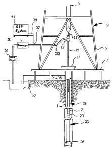
8 Figure 1A is a simplified depiction of a drilling rig, a drillstring
9 and a wellbore equipped with an apparatus for interrogating the borehole
in accordance with the present invention;
11 Figure 1 B is a partial longitudinal section view of a
12 measurement tubular and measurement sonde in accordance with the
13 present invention;
14 Figure 1C is a simplified schematic view of the antenna
arrangement of the measurement sonde of Figure 1 B;
16 Figure 1 D is a schematic depiction of the operation of the
17 transmitting and receiving antennas;
18 Figure 1 E depicts the phase shift which is detected by the
19 receiving antennas;
Figure 1 F is a graph which depicts the relationship between
21 resistivity and the detected phase shift;
DOCKET NO. 414-4780-US
_g_ _ 21543'8
1 Figure 1 G graphically depicts the amplitude attenuation of the
2 interrogating signal;
3 Figure 1 H depicts the graph of the relationship between
4 resistivity and the amplitude ratio;
Figures 2A through 2E depict the electronic components of
6 the logging apparatus in accordance with the present invention;
7 Figures 3A and 3B depict one particular embodiment of the
8 present invention;
9 Figures 4A, 4B, 4C, and 4D depict another embodiment of the
present invention.
DOCKET NO. 414-4780-US
-10- _ 2.~543~$
1 DETAILED DESCRIPTION OF THE INVENTION
2 With reference to Figure 1A, there will now be described an
3 overall simultaneous drilling and logging system in accordance with one
4 preferred embodiment of the present invention that incorporates an
electromagnetic wave propagation (EWP) resistiviiy measurement system
6 according to this invention.
7 A well 1 is being drilled into the earth under control of surface
8 equipment including a rotary drilling rig 3. In accord with a conventional
9 arrangement, rig 3 includes a derrick 5, derrick floor 7, draw works 9, hook
11, swivel 13, kelly joint 15, rotary table 17, and drill string 19 that
includes
11 drill pipe 21 secured to the lower end of kelly joint 15 and to the upper
end
12 of a section of drill collars including an upper drill collar 23, an
intermediate
13 drill collar or sub (not separately shown), and a lower drill collar
14 measurement tubular 25 immediately below the intermediate sub. A drill bit
26 is carried by the lower end of measurement tubular 25.
16 Drilling fluid (or "mud", as it is commonly called) is circulated
17 from a mud pit 27 through a mud pump 29, past a desurger 31, through a
18 mud supply line 33, and into swivel 13. The drilling mud flows down
19 through the kelly joint and an axial tubular conduit in the drill string,
and
through jets (not shown) in the lower face of the drill bit. The drilling mud
21 flows back up through the annular space between the outer surface of the
22 drill string and the inner surface of the borehole to be circulated to the
23 surface where it is returned to the mud pit through a mud return line 35. A
24 shaker screen (not shown) separates formation cuttings from the drilling
mud before it returns to the mud pit.
DOCKET NO. 414-4780-US
CA 02154378 2004-12-09
-11-
1 The overall system of Figure 1 uses mud pulse telemetry
2 techniques to communicate data from downhole to the surtace while drilling
3 operation takes place. To receive data at the surface, there is a transducer
4 37 in mud supply line 33: This transducer generates electrical signals in
response to drilling mud pressure variations, and these electrical signals are
6 ~ transmitted by a surface conductor 39 to a surface electronic processing
7 (SEP) system 41.
8 As explained in U.S. Patent No. 4,216,536 to More (More
9 '536 patent), mud pulse telemetry techniques provide for communicating
data to the surface about numerous downhole conditions sensed by well
11 logging transducers or measurement systems that ordinarily are located
12 on and within the drill collar nearest the drill bit. Measurement tubular
25
13 is preferably nearest the drill bit, as shown in Figure 1. The mud pulses
14 that define the data propagated to the surface are produced by equipment
~5 within the intermediate sub. Such equipment suitably comprises a
16 pressure pulse generator operating under control of electronics contained
17 within an instrument housing to allow drilling mud to vent through an
1g orifice extending through the logging collar wall. Each time the pressure
19 pulse generator causes such venting, a negative pressure pulse is
transmitted to be received by surface transducer 37. An alternative
21 conventional arrangement generates and transmits positive pressure
22 pulses.
23 The circulating drilling mud provides a source of energy for a
24 turbine-driven generator sub-assembly located in the intermediate sub; and,
25 the turbine-driven generator sub-assembly generates electrical power for
the
26 pressure pulse generator and for various circuits including circuits
forming
_214378
-12-
1 part of the preferred embodiment of this invention. As an alternative or
2 supplemental source of electrical power, batteries may be provided,
3 particularly as a back-up for the turbine-driven generator.
4 A measurement system embodying the present invention
includes electronics contained in electronics housings contained within
6 measurement sonde 27, and contains elements arranged in recesses or
7 necked-down portions of the tubular steel housing of measurement sonde
8 27. Some of these elements of measurement sonde 27 are indicated
9 schematically in Figure 1 C and include upper transmitting antenna 29, lower
transmitting antenna 31, and intermediate receiving antennas 33, 35 which
11 are carried about an exterior surface of measurement sonde 27, and which
12 are utilized to interrogate the borehole and surrounding formation, as will
be
13 discussed in greater detail herebelow. In alternative embodiments, a
greater
14 or lesser number of transmitting or receiving antennas may be utilized.
Figure 1 B depicts one embodiment of measurement tubular
16 25, which includes upper, internally threaded tool joint 37 and lower,
17 internally threaded tool joint 39, which are adapted to couple within a
18 drillstring, with a central section 41 disposed therebetween which is
formed
19 of a material which allows the inward and outward propagation of
electromagnetic fields, to allow the transmitting antennas 29, 31 and
21 receiving antennas 33, 35 of measurement sonde 27 to communicate with
22 the surrounding borehole and formation. In accordance with the preferred
23 embodiment of the present invention, central section 41 is formed of a
24 material which is either "poorly-conducting" or "non-conducting". For
purposes of this disclosure, semi-conductors are defined as materials which
26 have a bulk resistivity value of greater than 0.001 Ohm-meters and less
than
DOCKET NO. 414-4780-US
-13- _ 21~43'~8
1 100 Ohm-meters. For purposes of this disclosure, non-conducting
materials
2 are defined as those materials which have bulk resistivity
values which are
3 greater than 100 Ohm-meters. Also, for purposes of this disclosure,
"good"
4 conducting materials are defined as having a resistivity of
less than 0.001
ohm-meters. Central section 41 need merely be sufficiently
strong to
6 provide mechanical strength and convey wellbore fluids, but
while also
7 allowing electrical sensors located within the interior of
measurement tubular
8 25 to transmit and receive oscillating electric and/or magnetic
fields which
9 are too high in frequency to penetrate the conventional prior
art steel drill
collars. As stated above, the prior art steel collars responded
to high
11 frequency electric and/or magnetic oscillating fields by the
generation of
12 eddy currents which dissipated the field and prevented the
communication
13 inward or outward of electric and/or magnetic oscillating
fields. Preferably
14 central section 41 may be composed of KEVLAR-based composite
materials. An example of one type of composite tubulars which
are
16 currently being utilized in the oil and gas industry are the
composite drill
17 pipe; casing pipe, and tubing pipe manufactured by Brunswick
Composites,
18 a unit of the Brunswick Technical Group, having a business
and
19 correspondence address in Lincoln, Nebraska, which offers
for sale
composite tubulars which have a strength many times greater
than that
21 found in steel tubulars, with much less weight, and virtual
immunity to
22 corrosion. An article entitled "Developments in Composite
Structures for the
23 Offshore Oil Industry" by J. G. Williams of Conoco, Inc.,
published in May
24 of 1991 at the Offshore Technology Conference, and identified
by OTC No.
6579, provides a detailed statement of the current utilization
of composite
26 materials in offshore oil and gas activities. Among the numerous
uses of
27 composite materials identified in this article is the use
of composite drill pipe
28 which has demonstrated its ability to withstand the forces
encountered
DOCKET NO. 414-4780-US
_14_ _215~3'~
1 during drilling operations. Numerous composite materials are identified in
2 this article including composites based upon graphite, KEVLAR 29, and
3 KEVLAR 49.
4 In the present invention, since only azimuthal transmission of
the electromagnetic wave is desired, the measurement tubular need only be
6 transmissive of electromagnetic waves which are traveling inward relative to
7 the measurement sonde or outward relative to the measurement sonde.
8 The measurement tubular need not be transmissive of electromagnetic fields
9 along its central longitudinal axis. In the embodiment of Figure 1 B, the
entire measurement tubular is constructed of a material which is
11 transmissive of electromagnetic fields; however, in alternative
embodiments,
12 such as those depicted in Figures 3A, 3B, 4A, 4B, 4C, and 4D, only
13 portions of the measurement tubular need be formed of a material which
14 allows the inward and outward passage of electromagnetic fields. In the
particular embodiments depicted and described herein, a plurality of axial
16 slots may be formed in a conventional steel tubular. The axial slots are
filled
17 with composite material which is transmissive of electromagnetic fields. Of
18 course, the measurement sonde and the measurement tubular should be
19 aligned so that the antenna is placed proximate the axial slots, and
allowed
to either transmit electromagnetic fields outward through the axial slots, or
21 to receive magnetic fields which are traveling radially inward through the
22 axial slots.
23 The operation of measurement sonde 27 is depicted in
24 schematic and graphical form in Figures 1 D, 1 E, 1 F, 1 G, and 1 H. As is
depicted in schematic form in Figure 1 D, transmitting antennas T~, T2 are
26 spaced on both sides of a pair of receiving antennas R~, R2, allowing the
DOCKET NO. 414-4780-US
214378
-15-
1 measurement of both phase and amplitude. The transmitters and receivers
2 are simple antennas consisting of a loop of wire imbedded in an insulating
3 material, with tuning capacitors to trim the antenna response. The tool can
4 be thought of as a pair of sensors, whose output is the average of two
readings, reducing tool error from the temperature and pressure affects, tool
6 misalignment, borehole washout and bed shoulder effects. In a vacuum,
7 the finite velocity of electromagnetic radiation leads to a small phase
shift
8 between the two receivers R,, R2, while the increased distance to the far
9 receiver causes the signal strength to be weaker at that point. In a more
conductive formation, the radiation moves more slowly and attenuates more
11 rapidly. As a result, either the difference in phase between the two
12 receivers, or the ration of amplitudes may be used to measure formation
13 resistivity. As is shown in Figure 1 D, two amplitude and phase readings
are
14 made, and then averaged. An upper transmitter reading X2 is made utilizing
upper transmitting antenna T2 to propagate an electromagnetic wave
16 outward through measurement tubular 25 (which is not depicted) and into
17 the formation, and then back through measurement tubular 25 to be
18 measured by the intermediate receiving antennas R,, R2. Then, the lower
19 transmitter reading X, is made utilizing lower transmitting antenna T, to
send
an electromagnetic wave outward through measurement tubular 25 (not
21 depicted) into the formation, and then back through measurement tubular
22 25 to be measured by intermediate receiving antennas R~, R2. The
23 compensated reading is the arithmetic average of lower transmitter reading
24 X~ and upper transmitter reading X2.
In the preferred embodiment, the primary measurement is
26 phase resistivity which can be described with reference to Figure 1 E. It
is
27 easy to see from this illustration that the greater the spacing between the
DOCKET NO. 414-4780-US
21543'~~
-16-
1 two receiving antennas R~, R2, the larger the observed phase difference
2 between the receiving antennas. The phase measurement is converted to
3 resistivity, with only small effects from the dielectric constant, after
averaging
4 the values from both transmitters. Figure 1 F is a graph which plots
resistivity in Ohms-meter to phase difference in units of degrees. A family
6 of curves is shown for different relative dielectric constants (for the
specific
7 dielectric constant values of 1, 10, and 100).
8 Figure 1 G depicts the amplitude attenuation which occurs as
9 the electromagnetic wave propagates through the formation. A two
megahertz wave, under downhole conditions, propagates only a few feet
11 before the signal strength fades away, so the rate of attenuation or
12 amplitude ratio of the signal is also measured. Figure 1 G graphically
13 depicts the attenuation of the signal from its original signal strength as
it
14 passes through measurement tubular 25 and the surrounding formation.
Measurements made at receiving antennas R,, R2 can be used to develop
16 an amplitude ratio which is representative of the amount of attenuation
that
17 the interrogating signal experiences as it travels between receiving
antenna
18 R~ and receiving antenna R2. In the preferred embodiment of the present
19 invention, the tool utilizes a microprocessor with memory to store values
of
the amplitude for each transmitter into memory, and then computes the ratio
21 of amplitudes for each transmitter, averaging the values for each
transmitter
22 to produce a compensated ratio. The amplitude ratio is then transformed
23 to resistivity. Figure 1 H is a graph which plots the relationship of
resistivity
24 in units of Ohms-meter to the amplitude ratio, for a plurality of differing
relative dielectric constants (and specifically for the relative dielectric
26 constant values of 1, 10, and 100).
DOCKET NO. 414-4780-US
_21437$
-17-
1 The following discussion illustrates how the dual transmitter,
2 dual receiver measurement-while-drilling apparatus of the present invention
3 is utilized to derive an accurate measure of the amplitude attenuation and
4 phase shift of the interrogating electromagnetic signal which travels
through
the borehole and surrounding formation.
6 First, consider four transmitter-to-receiver signals:
7 (Transmitter 1 [X1] to Receiver 1 [R1]): A,~ e~"
8 (Transmitter 1 [X1 ] to Receiver 2 [R2]): A~2 e~'2
9 (Transmitter 2 [X2] to Receiver 1 [R1]): A2~ e~2'
(Transmitter 2 [X2] to Receiver 2 [R2]): A~ e~~
11 The measured amplitudes are made up of:
12 Amn = Xm Rn a~n (Eq. 1.1 )
13 where Xm = transmitter output variation
14 Rn = receiver sensitivity variation
au"n = true amplitude (transmitter M to receiver N);
16 and the measured phases are made up of:
17 ~ mn = ~ xm + ~ Rn ~' ~ tmn (Eq. 1.2)
18 where ~ xt, = transmitter phase (output) variation
1 9 ~ ~, = receiver phase variation
~ tmn = true phase (transmitter M to receiver N)
DOCKET NO. 414-4780-US
_ 18 __ 21543'~~
1 The foregoing general equations correspond to the following
2 more specific equations:
3 A,~ = X~ R~ a~"
4 A,2 = X, R2 aC,2
A2~ = X2 R~ ate,
6 A~ = X2 R2 a~
7 ~ =~x~ +~R~ +~tm
~ ~2 = ~x~ + ~ R2
+ ~c~2
'r21 -~X2 +~R1 +~'t21
~~ _~~+~~+~~
11 Taking rations of the various transmitter-to-receiver signals
12 produces the following:
13 For Transmitter 1:
DOCKET NO. 414-4780-US
_ 19 _ _ 214378
1
_________ _ ____ a ~~,2 -~ ")
3
and for Transmitter 2:
6 ___'_____ _ ____* a ~E 2, -~ ~)
Multiplying these and taking the square root gives:
At2 * e1 ~1t2 - ~tt~ * ~ * e~ib2t - ~
~11
~12 * A21 e! Y~(~tt ~ ~2t - ~tt - ~
"t 1 * ~2
Straightforward algebraic manipulation of Eqs. 1.1 through 1.3
yields:
DOCKET NO. 414-4780-US
_ 2154~'~$
-20-
$hp * 8~' 1 * efYs(~t12 i;t21 -;t11 - ~t2~
8t11 * 8t22
1 because all the system variables drop out of the measurement.
2 Therefore, by using two transmitters and two receivers,
3 systematic variables can be removed from both the attenuation (amplitude)
4 and from the phase velocity (phase difference) terms.
Within the context of the preferred embodiment of this
6 invention, in which a sampled-data processing means produces a signal as
7 a function of formation resistivity based on phase-representing signals, the
8 following analysis demonstrates certain matter relevant to the stability
9 feature.
Consider two consecutive samples: Sample A and Sample B.
11 During Sample A, a first transmitting coil is energized to cause
12 a wave to propagate through the formation in a direction such that the wave
13 passes a first receiving coil (R1), and later passes a second receiving
coil
14 (R2), and induces each receiver coil to produce a signal.
During Sample B, a second transmitting coil is energized to
16 cause a wave to propagate through the formation in a direction such that
17 the wave passes a second receiving coil (R2), and later passes the first
18 receiving coil (R1), and induces each receiver coil to produce a signal.
DOCKET NO. 414-4780-US
215437$
_21 _ _
1 Let ~ MR2A represent the measured phase of the signal
2 produced by receiver coil R2 during Sample A; let ~ MR1A represent the
3 measured phase of the signal produced by receiver coil R1 during Sample
4 A; let ~ MR1 B represent the measured phase of the signal produced by
receiver coil R1 during Sample B; and let ~ MR2B represent the measured
6 phase of the signal produced by receiver coil R2 during Sample B.
7 The ~ MR2A signal depends on the phase of the wave at the
8 location of R2, and in general, has an error component attributable to
9 various phase shifts including those introduced by the tuned receiver coil,
cabling from the receiver coil to the receiver, and the receiver itself. Let
11 ~ TR2A represent the true phase of the wave at the location or R2 during
12 Sample A, and let c~ R2E represent the error component so introduced.
13 Eq. 2.1: ~ M R2A = ~ TR2A + ~ R2E
14 Similarly, they MR1A signal depends on the phase of the wave
at the location or R1, and in general, has its own error component. Let
16 ~TR1A represent the true phase of the wave at the location of R1 during
17 Sample A, and let ~ R1 E represent the error component so introduced.
18 Eq. 2.2: ~MR1A =~TR1A +~R1E
19 During Sample A, the ~ MR1A signal and the ~ MR2A are
simultaneously processed to produce a DeItaA signal that represents the
21 difference in phase between these two signals (i.e., ~ MR1 a - ~ MR2A).
22 Eq. 2.3: Delta A = (~ TR2A - ~ TR 1 A) + (~ R2E - ~ R 1 E)
23 The component of the DeItaA signal representing the true
24 phase difference (~TR2A - ~TR1A) is a function of the resistivity of the
DOCKET NO. 414-4780-US
-22- _ 21543'8
1 formation in the region between the two receiver coils. Let F(rho) represent
2 this component.
3 Eq. 2.4: DeItaA = F(rho) + (~ R2E - ~ R1 E)
4 Similarly, during Sample 8, the ~ MR2B signal and the ~ MR1 B
are simultaneously processed to produce a DeItaB signal that represents the
6 difference in phase between these two signals (i.e., ~ MR2B -~ MR1 B).
7 Eq. 2.5: ~MR1B = ~TR1B + ~R1E
8 Eq. 2.6: ~ MR2B = ~TR2B + ~ R2E
9 Eq. 2.7: DeItaB = (~ TR1 B - ~ TR2B) + (~ R1 E - ~ R2E)
The component of the DeItaB signal representing the true
11 phase difference (~TR1B - ~TR2B) is a function of the resistivity of the
12 formation in the region between the two receiver coils; i.e., it equals
f(rho).
13 Eq. 2:8 DeItaB = f(rho) + (~ R1 E - ~ R2E)
14 The Delta A signal is recorded so that it can be retrieved and
processed with the Delta B signal.
16 By adding Equations 2.7 and 2.8, it follows that:
17 DeItaA + DeItaB = 2 * f(rho) + ~ R2E - ~ R1 E - ~ R2E + ~ R1 E and
18 Eq. 2.9: f(rho) = 1 /2 * (DeItaA + DeItaB)
19 In other words, a computed signal representing the sum of the
consecutive samples is a function of formation resistivity, and error
21 components such as ~ R1 E and ~ R2E do not introduce errors into this
22 computed signal.
DOCKET NO. 414-4780-US
2.54378
-23-
1 Figures 2A, 2B, 2C, 2D, and 2E depict the electronics carried
2 by measurement sonde 27 in block diagram and electric schematic form.
3 As is shown in Figure 2A, processor 101 directs the operation of drive
4 circuits 105, 107 and receiver circuit 103. Drive circuit 107 operates to
energize selectively transmitting antenna T2, while drive circuit 105 operates
6 to energize selectively transmitting antenna T,. Receiver circuit 103
receives
7 the measurements of the electromagnetic field made by receiving antennas
8 R~, R2. Processor 101 supplies data to telemetry system 109, and receives
9 instructions from telemetry system 109. Telemetry system provides the
electrical commands to a mud pulse telemetry actuator which is in
11 communication with a fluid column in the wellbore, and which is utilized to
12 impress a coded message in the fluid column.
13 The principle components of the electronics carried by
14 measurements sonde 27, which are depicted in block diagram form in
Figure 2A, are depicted in detail in Figures 2B, 2C, 2D, and 2E, with
16 Figures 2B, 2C, and 2D respectively depicting the dual receiver 111,
17 amplitude/phase detector 113, and the local oscillator 115 which comprise
18 the significant operational components of receiver circuit 103, and with
19 Figure 2E depicting drive circuit 107 of Figure 2A, which is identical to
drive
circuit 105, of Figure 2A.
21 First with reference to Figure 2B, there is depicted dual
22 receiver 111 in simplified electrical schematic form. In broad overview,
the
23 signals from receiving antennas R,, R2 are fed to dual receiver 111. The
24 signals are amplified at RF amplifiers 119, 121 and heterodyned with the
output of the 1.995 megahertz local oscillator 117, which provides a
26 resultant 5 kilohertz intermediate frequency (I F). The intermediate
frequency
DOCKET NO. 414-4780-US
21543~~
-24- -
1 will retain the phase relationship of the two receiver signals by using a
2 common oscillator for mixers 123, 125. The signals are passed to
3 intermediate frequency (IF) amplifiers 127, 129 for further amplification.
The
4 signals are then passed through 500 hertz band pass filters 131, 133 before
being fed to the amplitude/phase detector 113 of Figure 2C.
6 Now more particularly, the dual receiver 111 of Figure 2B
7 receives the 2 megahertz signal from receiving antennas R,, R2, which are
8 coupled to the input of RF amplifiers 119, 121. The coupling components
9 are specifically selected to minimize phase shift with temperature. The RF
amplifiers 119, 121 have a gain of l5db and the output is coupled to the
11 balanced mixers 123, 125. The output of the local oscillator is injected to
12 the mixer via a power splitter arrangement to provide equal amplitudes with
13 zero degrees of phase shift to each mixer. The splitter, combined with a
14 6db attenuator, will ensure the proper level and also minimize cross talk
between the two mixers. A balanced mixer is used to minimize local
16 oscillator feed-through to the output. The mixer stage has a gain of 20db.
17 The mixer output is fed through five kilohertz low pass filters 135, 137
and
18 coupled to the non-inverting input of IF amplifiers 127, 129, which
provides
19 an l8db gain. The output of IF amplifier 127, 129 is fed through 500 hertz
band pass filter op amps 131, 133 which provide a 20db gain. This final
21 amplification has a very high Q 500 hertz band pass filter. The passive
22 components of the filter must be matched to ensure minimal phase shift with
23 frequency and temperature. It is important that both filters remain
matched.
24 The amplitude/phase detector 113 is depicted in Figure 2C.
The amplitude/phase detector 113 has a separate automatic gain (AGC)
DOCKET NO. 414-4780-US
2154~~
-25-
1 circuit for each IF signal received, which provides constant amplitudes for
2 the phase detector. The AGC circuit's control voltage to the is proportional
3 to the amplitude of the IF signal providing a DC signal corresponding to the
4 received signal level. The DC level is used by the processor as the
amplitude of the received signal level. The output of the phase detector is
6 a pulse which is proportional to the phase shift between the two IF signals.
7 This voltage is integrated and amplified to provide phase outputs of
100°
8 and 20°. The resultant signal is fed to the microprocessor board
which
9 initiates a measurement cycle, times the events during that cycle, samples
data from the receiver, stores data in memory, and communicates with a
11 tool bus.
12 The automatic gain control circuit has a dual purpose: to
13 detect the amplitude of the incoming signal from the dual receiver 111 of
14 Figure 2B, and to maintain a constant amplitude signal to the phase
detector. The automatic gain control contains for each channel an Analog
16 Devices linear divider 139, 141. The output of the linear dividers 139, 141
17 (V~ is equal to the intermediate frequency IF divided by a DC level (V=).
18 The output of each analog divider 139, 141 is connected to low pass filter
19 143,145, with a cut off of 7.5 kilohertz to remove any high frequency
noise.
This signal is fed to an RMS-to-DC converter 147, 149. An error amplifier
21 155, 157 compares the output of converters 147, 149 to a reference signal
22 provided by reference signal generators 151, 153, and generates a control
23 voltage dependent upon the difference. To prevent a loop lock-up, negative
24 values resulting from the loss of signal are diode-blocked by diodes 159,
161 which are coupled between error amplfiers 155, 157 and output buffers
26 163, 165. The control voltage is fed to the automatic gain control to
27 maintain a constant output, and to the processor for amplitude information.
DOCKET NO. 414-4780-US
21543'~~
-26-
1 The IF signals from the automatic gain control circuit are capacitively
2 coupled to inverting buffers 167, 169 for phase detection, to eliminate any
3 DC offset. Preferably, the IF2 signal is inverted 180°. This allows
the output
4 of the phase detector to be in the range of -180° to + 180°,
instead of being
in the range of 0° to 360°. The signals are then squared-up with
a zero
6 crossing detector 171, 173, and passed to a 4013 dual flip-flop set which
7 function as phase detector 175. To accomplish this, the supply voltage flip-
8 flop is not grounded. Instead, a positive voltage is powered from a floating
9 supply so that what would normally be considered a low voltage {ground)
will be a negative voltage or -180°. Likewise, a high level will be a
positive
11 voltage, or + 180°. The clock inputs are used so that the phase
detector will
12 not be sensitive to cycle variation in the IF square waves. The phase
13 detector output will be as follows:
14 (1 ) a square wave input from receiver R, intermediate frequency
IF, sets pin 1 high;
16 (2) a square wave input from receiver R2 intermediate frequency
17 IF sets pin 13 high;
18 (3) a high on pin 13 resets both flip-flops sending pin 1 low.
19 If the receive signals are in phase, the signals to the flip-flop
would have 180° of phase difference due to the inversion of IF2. This
would
21 result in the phase detector having a 50% duty cycle on pin 1, switching
22 between negative 4.5 volts and positive 4.5 volts. This would result in
zero
23 volts on the low pass filter of integrator amplifier 177. As the phase
24 differential increases, so does the positive pulse width, causing a
negative
voltage out. Likewise, a negative phase input causes a negative pulse width
26 resulting in a negative DC level from the filter. The gain in the low pass
filter
27 is set so that 100° equals 5 volts. This signal is used by the
processor for
DOCKET NO. 414-4780-US
2.14378
-27-
1 the plus or minus 100° input and is also amplified five times by DC
amplifier
2 179, for the 20° of phase difference to equal a 5 volt output.
3 Figure 2D depicts a local oscillator 115 which generates the
4 1.995 megahertz injection for the receiver mixers of Figure
2B. Local
oscillator 115 consists of a voltage controlled oscillator,
a phase lock loop,
6 and a final amplifier. A 20 kilohertz reference is supplied
for the phase lock
7 loop. A voltage controlled crystal (Colpitts) oscillator is
utilized to reduce
8 frequency error due to vibration downhole. The voltage controlled
oscillator
9 is locked to a reference frequency so the IF will be 5 kilohertz.
A higher
frequency crystal (7.982 megahertz) is used to increase the
tuning range of
11 the circuit. The oscillator is tuned to the desired center
frequency by
12 variable capacitance diodes VC1 and VC2. Control voltage for
the diodes
13 is supplied by the phase lock loop as follows. The output
of the oscillator
14 is divided by 4 to obtained the desired 1.995 megahertz frequency
which is
coupled to pin 9 of an MC14569 programmable binary down counter.
To
16 achieve a division ratio of 399, the MC14569 is cascaded with
the
17 programmable counter in the MC14568. The remaining counter
in the
18 MC14568 is used to divide the 20 kilohertz reference by 4
to provide a 5
19 kilohertz reference for the phase detector. The 5 kilohertz
out of the divider
(1.995/399) is compared to the 5 kilohertz reference by the
MC14568 phase
21 detector. Pulses out of the phase detector on pin 13 represent
the
22 frequency error between the divided 1.995 megahertz and the
5 kilohertz
23 reference. These pulses are integrated by capacitor C4 to
provide a
24 correction voltage for diodes VC1 and VC2 to bring the oscillator
back on
frequency. The 1.995 megahertz is buffered by three 4049 inverters
which
26 are tied in parallel. A Pi network is used to match the output
of the 4049's
27 to 90 Ohms and also attenuate the harmonics of the 1.995 megahertz
DOCKET NO. 414-4780-US
215437
_28_ _
1 square wave. The power output of the local oscillator is approximately 10
2 milliwatts or + 1 Odbm.
3 Figure 2E depicts drive circuit 107 of Figure 2A, which is
4 identical to drive circuit 105 of Figure 2A. Each drive circuit is
identical,
except that each has a different transmit control voltage. Each transmitter
6 drive circuit consists of a voltage controlled crystal oscillator, a phase
lock
7 loop, a final amplifier, and a transmitter on/off control. The 20 kilohertz
8 reference is provided. To ensure a satisfactory lock range, a 8 megahertz
9 voltage controlled crystal oscillator is used in the transmitters. The
frequency is adjusted by the variable capacitants of VC1 and VC2. The
11 output is divided by 4 to obtain the desired 2 megahertz final frequency.
12 The two megahertz output signal is coupled to the phase lock loop, which
13 in turn divides the 2 megahertz signal by 100 to obtain the 20 kilohertz
14 reference frequency to compare with the 20 kilohertz from the phase
detector. Pulses from the phase detector represent the frequency error. A
16 correction voltage is supplied to VC1 and VC2 to bring the oscillator back
~ 7 on frequency. The 2 megahertz signal is also tied to U2 which controls the
18 output of the transmitter. The output stage is driven into class D
operation
19 by using a square wave input which results in higher amplifier efficiency.
A
low pass filter is used to reduce the harmonics. The cut off for this filter
is
21 3 megahertz. The power output of the transmitter is approximately 0.5 watts
22 (27dbm).
23 Figures 3A, 3B, 4A, 4B, 4C, and 4D depict two embodiments
24 of the present invention. Figures 3A and 3B depict measurement tubular
401 and measurement sonde 419 which is adapted to be positioned within
26 the central bore 410 of measurement tubular 401. Measurement tubular
DOCKET NO. 414-4780-US
-29- _ 2.5437
1 401 is composed substantially of steel, as are other prior
art drill collars;
2 however, measurement tubular 401 includes four regions which
include a
3 plurality of axial slots which are disposed circumferentially
about
4 measurement tubular 401 and which extend through the width
of
measurement tubular 401, but which are filled with a poorly-conducting
or
6 non-conducting material, such as a KEVLAR material or such
as an epoxy
7 or ceramic material. The axial slots which are filled with
non-conducting or
poorly-conducting material allow for the inward and outward
passage of
9 electric and/or magnetic oscillating fields, but which prevent
the passage of
fluid through measurement tubular 401. As is shown in Figure
3A, upper
11 transmitter region 402 includes the axial slots which allow
for the inward and
12 outward passage of electric and/or magnetic oscillating fields.
Likewise,
13 lower transmitter region 407 includes the axial slots which
allow for the
14 inward or outward passage of electric and/or magnetic oscillating
fields.
Receiver regions 403, 405 are provided in a position intermediate
the
16 transmitter regions 402, 407. Receiver regions 403, 405 also
include the
17 axial slots filled with poorly-conducting or non-conducting
material, which
18 allow for the inward or outward passage of electric and/or
magnetic
19 oscillating fields. The regions which contain the axial slots
filled with poorly-
conducting or non-conducting material are separated and surrounded
by
21 solid regions 409, 411, 413, 415, and 417, which do not allow
for the
22 passage of electrical and/or oscillating fields, since they
are composed of
23 steel which dissipates the electrical and/or magnetic oscillating
field by the
24 formation of eddy currents. Measurement sonde 419 is disposed
adjacent
measurement tubular 401 in the depiction of Figure 3A. In
actual use,
26 measurement sonde 419 is disposed within the central bore
(which is
27 depicted only in Figure 3B) of measurement tubular 401. Measurement
28 sonde 419 is composed of upper transmitter assembly and pressure
DOCKET NO. 414-4780-US
2.54378
-30-
1 housing 421 which contains the upper transmitting antenna, receiver
2 assembly and middle pressure housing 425 which contain the receiving
3 antennas, and lower transmitter assembly and pressure housing 429 which
4 contain the lower transmitter. Upper paddle assembly 423 and lower
paddle assembly 427 are provided to centralize and position measurement
6 sonde 413 within the central bore of measurement tubular 401. The
7 electrical, electronic, and data processing components which cooperate to
8 allow for the reception and transmission modes of operation are contained
9 within the pressure housings 421, 425, 427. Upper transmitter 431 is
disposed on the exterior surface of upper transmitter assembly and
11 pressure housing 421 and is adapted to be aligned with transmitter region
12 402 when measurement sonde 419 is positioned within the central bore of
13 measurement tubular 401. Lower transmitter 437 is carried about the
14 exterior portion of lower transmitter assembly and pressure housing 429 and
is adapted in position to be aligned v~i~th transmitter region 407 of
16 measurement tubular 401 when measurement sonde 419 is positioned
17 within the central bore of measurement tubular 401. Receiver antennas 433,
18 435 are carried by receiver assembly and middle pressure housing 425 and
19 adapted in position to align with receiver regions 403, 405 when
measurement sonde 419 is positioned within the central bore of
21 measurement tubular 401. The axial slots in measurement tubular 401
22 which are filled with poorly-conducting or non-conducting material allow
for
23 the sonde-based measurement of well parameters outside the drillstring
24 which would normally be impeded by the presence of a steel collar. The
slots are constructed such that the collar of measurement tubular 401
26 maintains its structural integrity necessary for drilling operations, and
drilling
27 fluids are not allowed to flow through the axial slots since the non-
DOCKET NO. 414-4780-US
_31 _ 2~~4378
1 conducting or poorly-conducting materials are solid fluid-impermeable
2 materials.
3 Figure 3B is a partial longitudinal section view of measurement
4 sonde 419 disposed within central bore 410 of measurement tubular 401.
As is shown, electronics cavities 412, 414 are provided above and below
6 antenna section 416. Antenna section 416 includes an antenna cavity 418
7 which is filled with fiberglass 420, which surrounds antenna wire 422.
8 Antenna section includes antenna housing sleeve 422 which includes upper
9 lip 424 and lower lip 426 which mate with mandrel 428 and mandrel 430 of
measurement sonde 419. As is shown, mud flows between measurement
11 tubular 401 and measurement sonde 419. The electronics contained within
12 electronics cavities 412, 428 are protected from the mud flow.
13 Figure 4A depicts an alternative embodiment of the present
14 invention which is especially useful in slim-hole applications. For
purposes
of this application, Nslim hole" applications are these which utilize tubulars
16 having and oud outer diameter of six (6) inches or less. Measurement
17 sonde 503 is shown disposed within central bore of measurement tubular
18 501. Preferably, measurement tubular 501 is formed of a reduced radial
19 diameter in the range of three to four inches. Measurement sonde 503 is
adapted to engage the central bore of measurement tubular 501, in the
21 areas of the antennas so that the antennas can be as large in diameter as
22 possible and so that the antennas can serve a second purpose and locate
23 the sonde 503 within the bore 501. Measurement sonde soa inch mpg a
24 controller and transmitter electronics subassembly 507, transmitter antenna
509, receiver electronics subassembly 511, receiver antennas 513, 514,
26 transmitter electronics housing 515, and transmitter antenna 517. Figure
DOCKET NO. 414-4780-US
2~54~'~$
- 32 -
1 4B is a detail view of the region of transmitter 517. Measurement tubular
2 501 is shown in fragmentary section view. It is equipped with a plurality of
3 axial slots 525 which are filled with poorly-conducting or non-conducting
4 epoxy or KEVLAR material. Transmitter 517 is carried adjacent the axial
slots 525. Figure 4C is a cross-section view as seen along section lines C-
6 C of Figure 4A. As is shown, a plurality of spokes 527 and axial slots 529
7 are provided. Drilling mud is pumped downward through axial slots 529 in
8 the region of the antennas. This arrangement has several significant
9 advantages over the prior art. Frst, the measurement sonde 503 may be
mechanically supported by measurement tubular 501 preventing movement
11 of measurement sonde 503. Second, the close alignment between
12 measurement tubular 501 and measurement sonde 503 prevents the flow
13 of drilling fluids in the region of the transmitting and receiving
antennas, thus
14 minimizing the possibility of damage to the antennas. Third, the
transmitting
and receiving antennas are placed as closely as possible to the axial slots
16 in measurement tubular 501 to increase measurement efficiency and reduce
power requirements for the logging tool. The measurement tubular can of
18 course be constructed of a non-conducting or poorly-conducting collar as
19 described earlier instead of a slotted collar.
Figure 4D is a longitudinal section view taken along section
21 line D-D of Figure 4C. As is shown, measurements on 503 is disposed
22 within central bore 510 of measurement tubular 501. Electronic cavities
23 512, 514 are provided for housing the logging tool electronics. Antenna
24 section is provided with a C-shaped sleeve which is filled with fiberglass
516, and which houses antenna wire 518. Flowpaths 520, 522 are provided
26 between C-shaped sleeve and the main body of measurement sonde 503.
27 Drilling mud is routed through flow passages 520, 522 in the region of
DOCKET NO. 414-4780-US
2~.543'~~
1 antenna 518. Antenna 518 is placed as closely as possible to measurement
2 tubular 501, which may be formed from a poorly-conducting material, or
3 which may include axial slots which allow for the inward and outward
4 passage of electromagnetic fields.
The embodiments discussed herein have focused on the
6 utilization of resistivity logging tools within measurement tubulars which
are
7 formed at least in-part by a poorly-conducting or non-conducting material;
8 however, other types of measurement tools may be formed in and carried
9 on measurement sondes which are placed inside measurement tubulars
which are partially formed of non-conducting or poorly-conducting materials,
11 such as dielectric logging tools and other tools which utilize oscillating
12 electric and/or magnetic fields to sense or detect conditions exterior of
the
13 logging tool which relate to either the borehole or surrounding formation.
14 One example of such a dielectric logging tool which can be used as is
described in the present invention is set forth in U.S. Patent No. 4,107,598
16 to Meador et al. In alternative embodiments, resistivity and dielectric
logging
17 tools may be combined in a single sonde to allow for multiple types of
18 measurement to occur simultaneously or successively. The types of
19 information which can be derived from resistivity and dielectric logging
tools
can be util'~zed to define a plurality of borehole and formation conditions,
21 including a measure of the borehole diameter, a measure of the diameter
22 of invasion of drilling muds, a measure of the formation resistivity, and
the
23 utilization of amplitude attenuation and phase shift measurements (which
24 see differing depths of the formation) for the location and detection of
bed
and boundary changes. An example of the utilization of amplitude and
26 phase data to perform caliper operations in a wellbore, and to detect bed
27 and boundary changes is set forth in U.S. Patent No. 4,899,112 to Clark,
DOCKET NO. 414-4780-US
_ z~~437~
- 34 -
1 which is entitled "Well Logging Apparatus For Determining Formation
2 Resistivity At A Shallow Depth And A Deep Depth" .
3 In particular embodiments of the present invention, the
4 measurement sonde may be equipped with a conventional fishing neck
disposed at its upper most portion, which allows the measurement sonde
6 to be run into or out of the measurement tubular during drilling operations
7 utilizing a conventional wireline-base retrieval apparatus. Typically, the
8 retrieval apparatus includes a component which is profiled to engage the
9 fishing neck of the measurement sonde. In this way, the measurement
sonde may be removed for repair or replacement during drilling operations,
11 without requiring that the entire drillstring be pulled.
12 While the invention has been shown in only several preferred
13 forms, it is not thus limited but is susceptible to various changes and
14 modifications without departing from the spirit thereof.
DOCKET NO. 414-4780-US