Note: Descriptions are shown in the official language in which they were submitted.
94/21205 ~ ~ ~ PCTlUS93108616
METHOD FOR PREPARATION AND TRANSPLANTATION OF
VOLUTE GRAFTS AND SURGICAL INSTRUMENT THEREFOR
SACKCROUND OF THE INVENTION
The present invention relates in general to surgical
instruments and surgical techniques. Mare particularly, the
present invention is directed to a surgical tool for
transplanting sheets of retinal cells, epithelial tissue
and/or choroidal tissue in a volute configuration through a
standard-sized incision in the eye, a graft for
transplantation to the subretinal region of the eye, a method
for preparing such grafts for transplantation and a method for
reconstructing dystrophic retinas, retinal pigment epithelial
layers and choroids.
The retina is the sensory epithelial surface that
lines the posterior aspect of the eye, receives the image
formed by the lens, transducer this image into neural impulses
and conveys this information to the brain by the optic nerve.
The retina comprises a number of layers, namely, the ganglion
cell layer, inner plexiform layer, inner nuclear layer, outer
plexiform layer, outer nuclear layer, photoreceptor inner
segments and outer segments. The outer nuclear layer
comprises the cell bodies of the photoreceptor cells with the
inner and outer segments being extensions of the cell bodies.
The choroid is a vascular membrane containing large
branched pigment cells that lies between the retina and the
sclerotic coat of the vertebrate eye. Immediately between the
choroid and the retina is the retinal pigment epithelium which
1
SlJBSTITUTE SHEEP
WO 54/21205 ~~~~ ~ ~~J PCTIUS93108616
forms an intimate structural and functional relationship with
the photoreceptor cells.
Several forms of blindness are primarily related to
the loss of photoreceptor cells caused by defects in the
retina, retinal pigment epithelium, choroid or possibly other
factors (e.g. intense light, retinal detachment, intraocular -
bleeding). In several retinal degenerative diseases select
populations of cells are lost. Specifically, in macular
degeneration and retinitis pigmentosa, the retinal
photoreceptors degenerate while other cells in the retina as
well as the retina's central connections are maintained. In
an effort to recover what was previously thought to be an
irreparably injured retina, researchers have suggested various
forms of grafts and transplantation techniques, none of which
constitute an effective manner for reconstructing a dystrophic
retina.
The transplantation of retinal cells to the eye can
be traced to a report by Royo et al., Growth _23: 313-336
(1959) in which embryonic retina was transplanted to the
anterior chamber of the maternal eye. A variety of cells were
reported to survive, including photoreceptors. Subsequently
de1 Cerro was able to repeat and extend these experiments (del
Cerro et al., Invest. Ophthalmol. Vis. Sci. 26: 1182-1185,
1985). Soon afterward Turner, et al. Dev. Brain Res.
26:91-104 (1986) showed that neonatal retinal tissue could be
transplanted into retinal wounds.
In related studies, Simmons et al., Soc. Neurosci.
Abstr. 10: 668 (1984) demonstrated that embryonic retina could
be transplanted intracranially, survive, show considerable
normal development, be able to innervate central structures,
and activate these structures in a light-dependent fashion.
Furthermore, these intracranial transplants could elicit
light-dependent behavioral responses (pupillary reflex) that
2
suas~r«-ur~ sHE~r
~O 94121205 PCTIi1S93108616
were mediated through the host's nervous system. Klassen et
al.. E-xp. Neurol. 102: 102-108 (1988) and Klassen et al. Proc.
:vatl. Acad., Sci. USA 84:6958-6960 (1987).
, Li and Turner, Exp. Eye Res. _47:911 (1988) have
proposed the transplantation of retinal pigment epithelium
(RPE) into the subretinal space as a therapeutic approach in
the RCS dystrophic rat to replace defective mutant RPE cells
with their healthy wild-type counterparts. According to their
approach, RPE was isolated from six- to eight-day old black
eyed rats and grafted into the subretinal space by using a
lesion paradigm which penetrates through the sclera and
choroid. A 1 ml injection of RPE (40,000 - 60,000 cells) was
made at the incision site into the subretinal space by means
of a 10 ml syringe to which was attached a 30 gauge needle.
However, this method destroys the cellular polarity and native
organization of the donor retinal pigment epithelium which is
desirable for transplants.
del Cerro, (del Cerro et al., Invest. Oohthalmol.
Vis. Sci. 26: 1182-1185, 1985) reported a method for the
transplantation of tissue strips into the anterior chamber or
into the host retina. The strips were prepared by excising
the neural retina from the donor eye. The retina was then cut
into suitable tissue strips which were then injected into the
appropriate location by means of a 30 gauge needle or
micropipette with the width of the strip limited to the inner
diameter of the needle (250 micrometers) and the length of the
strip being less than 1 millimeter. While del Cerro reports
that the intraocular transplantation of retinal strips can
survive, he notes that the procedure has some definite
limitations. For instance, his techniques do not allow for
the replacement of just the missing cells (e. g.
photoreceptors) but always include a mixture of retinal cells.
. Thus, with such a transplant appropriate reconstruction of the
3
SUBSTITUTE SHEET
WO 94/21205 PCT/US93108616
dystrophic retina that lacks a specific population of cells
(e. g., photoreceptors) is not possible.
del Cerro et al.. Neurosci. Lett. 92: 2I-26, ,1988,
also reported a procedure for the transplantation of r
dissociated neuroretinal cells. In this procedure, the donor
retina is cut into small pieces, incubated in trypsin for 15 .
minutes, and triturated into a single cell suspension by
aspirating it through a fine pulled pipette. Comparable to
the Li and Turner approach discussed above, this procedure
destroys the organized native structure of the transplant,
including the donor outer nuclear layer; the strict
organization of the photoreceptors with the outer segments
directed toward the pigment epithelium and the synaptic
terminals facing the outer plexiform layer are lost.
Furthermore, no means of isolating and purifying any given
population of retinal cells (e. g. photoreceptors) from other
retinal cells was demonstrated.
It is believed by the present inventor that it is
necessary to maintain the photoreceptors in an organized outer
nuclear layer structure in order to restore a reasonable
degree of vision. This conclusion is based on the well known
optical characteristics of photoreceptors (outer segments act
as light guides) and clinical evidence showing that folds or
similar, even minor disruptions in the retinal geometry can
severely degrade visual acuity.
SUMMARY OF THE INVENTION
Among the objects of the present invention,
therefore, may be noted the provision of a method which
conserves relatively large expanses of tissue harvested from a
donor eye; the provision of such a method in which a
relatively large expanse of harvested tissue is so formed as
to enable the harvested tissue to be inserted into a
4
SUBSTITUTE SHEET
94!21205 ~ ~ ~ ~ ~ ~ PCTIUS93J08616
standard-sized incision in the eye; the provision of such a
method in which the polarity and organization of the cells'at
the time of harvest are maintained in the graft: and the
provision of a method for implantation of grafts to the
subretinal area of an eye.
~ Further among the several objects and features of
the present invention may be noted the provision of a graft
for use in the reconstruction of a dystrophic retina or rescue
of endogenous photoreceptor cells of an individual afflicted
with an inherited or acquired retinal disease which causes a
progressive loss of rods and subsequent eventual cone
dystrophy, dysfunction and/or loss; the provision of such a
graft which facilitates regrowth of photoreceptor axons by
maintaining the polar organization of the photoreceptor and
the close proximity of their postsynaptic targets with the
adjacent outer plexiform layer upon transplantation.
Further among the several objects and features of
the present invention may be noted the provision of a surgical
tool for use in the implantation method which forms the graft
for insertion into a standard-sized incision; and the
provision of a surgical tool for use in the transplantation
method which allows appropriate- retinotopic positioning and
which protects photoreceptors, retinal pigment epithelial
tissue, choroidal tissue and/or Bruch~s membrane from damage
prior to and as the surgical device is positioned in the eye.
Generally, the implantation method comprises coiling
an implantable material which is of sheet-like form to form a
volute. The convolutions of the volute are free of one
another for subsequent uncoiling of the implantable material
substantially to its original sheet-like form. An incision is
made in the host eye for the insertion of the volute to a
position between the retina and the underlying tissue of the
host eye. The incision is smaller than the incision that
5
SUBSTITUTE SHEET
WO 94121205 PCTIUS93108616
would be required for'insertion of the implantable material in
its uncoiled sheet-like form. The volute is inserted one end
first into the host eye through the incision to a position
between the retina and the underlying tissue. The volute
uncoils after its insertion to lie in sheet-Iike form between
the retina and the underlying tissue of the host eye and the
incision is closed.
Generally, the graft for implantation comprises a
layer of a non-toxic flexible composition which substantially
dissolves at body temperature and a material to be implanted
coiled to form a volute. The volute is insertable one end
first through the incision dimensioned in accordance with the
cross-sectional area of the volute to a position for
implantation, and then uncoiled to lie in sheet-like form at
the site of implantation.
Generally, the implement for the formation of a
volute comprises a tubular body open at one end and having a
funnel. A carrier enters one end first in the tubular body at
the open end thereof and is fed along the body into and
through the funnel. The engagement of the carrier as it is
fed through the funnel with an interior surface of the funnel
causes the carrier to coil into the volute. The volute exits
from a small end of the funnel.
Other objects and features of the invention will be
in part apparent and in part pointed out hereinafter.
BRIEF DESCRIPTION OF THE DRAWINGS
Fig. 1 is a photograph of a cryostat section of
normal rat retina as set forth in Example 1;
Fig. 2 is a photograph of a blinded rat retina
following constant illumination as set forth in Example 1;
Fig. 3 is a schematic of a donor retina;
Fig. 4 is a schematic of a flattened retina;
6
~O 94/21205 ~,~ ~$ ~ ~~ PCTIUS93108616
i
Fig. 5 is a schematic of a flattened retina
mounted to a substrate: . .
Fig. 6 is a schematic of a sectioned retina mounted
to a substrate;
Fig. 7 is a schematic of a laminate comprising a
retina section on a supporting, stabilizing substrate;
Fig. 8 is a schematic top plan view of the laminate
of Fig. 7, showing a graft (dashed lines) comprising a
photoreceptor cell layer and a supporting, stabilizing
substrate;
Fig. 9 is a schematic of the graft mounted on a
plate formed with spacers;
Fig. 10 is a schematic of the graft mounted on a
plate infused with molten gelatin with a cover plate;
Fig. 11 is a schematic of the top plate being
laterally slid off;
Fig. 12 is a schematic of the resulting graft;
Fig. 13 is a schematic of the graft being skived;
Fig. 14 is a schematic of the skived graft being
removed from the plate for transplantation;
Fig. 15 is a perspective view of a volute;
Fig. 16 is a side elevational view of an instrument
for coiling and implanting the graft with the coiled graft in
the funnel of the instrument;
Fig. 17. is a side elevational view of the
instrument with a lumen attached to the outside of the
instrument;
Fig. 18. is a side elevational view of the
instrument with the plunger advancing the volute.;
Fig. 19. is a horizontal section through an eye
illustrating a pays plane surgical approach With the
instrument extending partially across the eye;
7
SUBSTITUTE SHEET
CA 02158443 2001-12-19
Fig. 20 is a horizontal section through an eye illustrating a pars plana
surgical approach
with the instrument inserted into a bleb; and
Fig. 21 is a horizontal section taken along line 21--21 of Fig. 16
illustrating a ramp within
the instrument.
Corresponding reference characters indicate corresponding parts throughout the
several
views of the drawings.
DETAILED DESCRIPTION
As used herein, the term "donor" shall mean the same or different organism
relative to the
host and the term "donor tissue" shall mean tissue harvested from the same or
different organism
relative to the host.
Several forms of blindness, such as retinitis pigmentosa, retinal detachment,
macular
degeneration, and light exposure-related blindness, are primarily related to
the loss of the
photoreceptors in the eye. However, destruction of the photoreceptors does not
necessarily lead
to the loss of the remaining retina or axons that connect the retina to the
brain. Surprisingly, it
has been discovered that some degree of vision can be restored by replacing
damaged
photoreceptors with photoreceptors harvested from a donor and which are
maintained in their
original organization and cellular polarity. Furthermore, as fiirther
described in U.S. Patent
5,962,027, the transplantation of photoreceptor rods harvested from a donor
eye can "rescue"
endogenous cone photoreceptors within the retina and thus may restore or
preserve visual
sensitivity of existing cone photoreceptors. That is, it has been found that
transplanted rods exert
a trophic effect upon endogenous cone photoreceptors.
8
,21 r
94121205 ~ ~~~~ PCTIUS93108616
Fig. l.is a photograph of a cryostat section of
normal rat retina. Fig. 2 is a photograph of a cryostat '
section of a rat retina following constant illumination which
r destroys the photoreceptor (outer nuclear) layer while leaving
S other retinal layers and cells largely intact. In these and
subsequent figures, the retina or layers thereof, e.g., the
ganglion cell layer ("G"), inner plexiform layer ("IPL"),
inner nuclear layer ("INL"), outer plexiform layer ("OPL"),
outer nuclear layer ("ONL"), inner segments ("IS"), outer
segments ("OS"), and retinal pigment epithelium ("RPE"), are
shown, respectively, from top to bottom.
Referring now to Fig. 3, a photoreceptor graft for
implantation through an incision smaller than the width of the
graft in sheet-like form is prepared in accordance with a
method of the present invention. The graft, however, may
comprise other implantable material such as other retinal
cells, antiviral and antibiotic agents and/or other
pharmacologic agents.
A graft comprising photoreceptor cells is prepared
by removing a donor retina 50 comprising inner retina layers
52 and a photoreceptor layer 54 from a donor eye. The donor
retina 50 is flattened (Fig. 4) by making a plurality of cuts
through the retina from locations near the center of the
retina to the outer edges thereof (see Fig. 8). Cuts can be
made in other directions if necessary.
As shown in Fig. 5, the flattened retina 56 is
placed with the photoreceptor side 54 down on a gelatin slab
58 which has been surfaced so as to provide a flat surface 60
that is parallel to the blade of a vibratome apparatus. The
gelatin slab 58 is secured to a conventional vibratome chuck
of the vibratome apparatus. Molten four to five per cent
gelatin solution is deposited adjacent the flattened
retina/gelatin surface interface 61 and is drawn by capillary
9
SUSSTiTUTE SHEET
WO 94121205 ~,, ~ ~ 4 ~,~ PCTIUS93108616
action under the Flattened retina 56 causing the flattened
retina to float upon the gelatinslab 58. Excess molten
gelatin is promptly removed and the floating flattened retina
56 is then cooled to approximately 4oC with ice-cold Ringer's
solution that surrounds the gelatin block to cause the molten
gelatin to gel. The flattened retina 56 is thereby adhered to _
the gelatin block 58.
As shown in Fig. 6, the inner retina portion 52 is
sectioned from the top down at approximately 20 to 50
millimicrons until the photoreceptor layer 54 is reached,
thereby isolating the photoreceptor layer from the inner
layers of the retina, i.e., the ganglion cell layer, inner
plexiform layer, inner nuclear layer, and outer plexiform
Layer. When the photoreceptor layer 54 is reached, the
vibratome stage is advanced and a section from, approximately
50 to 300 millimicrons thick is obtained as shown in Fig. 7.
The thickness of this section should be sufficient to undercut
the photoreceptor and form a section 62 consisting of a layer
of photoreceptor cells and a thin gelatin substrate 58 adhered
thereto. As shown in Fig. 8, the section 62 is cut vertically
along the dashed lines to create a laminar_e 63.
The laminate 63 is then placed onto a flat plate 64
formed with risers 66 as shown in Fig. 9. The plate 64, with
the laminate 63 positioned between the risers 66, is infused
with molten fifteen tc twenty per cent gelatin solution to
surround and cover the photoreceptor layer 54 with the gelatin
substrate 58 is surrounded and covered by the molten gelatin.
As shown in Fig. 10, a flat cover plate 68 is placed on top of
the risers b6 to remove any excess molten gelatin and to
establish the,precise thickness of the graft. The height of
the risers 66 can be adjusted to prepare grafts of different
thicknesses.
SUBSTITUTE SHEET
CA 02158443 2001-12-19
The resulting container 67 consisting of two plates 64, 68 separated by risers
66 encasing
a gelatin slab 69 with the photoreceptor layer 54 embedded therein is cooled
to room
temperature to cause the molten gelatin to gel and form a carrier sheet 70
encapsulating the
photoreceptor layer 54. The outer segrr~ent (not shown) of the photoreceptor
layer 54 faces
toward one face 71 of the carrier sheet 70.
As shown in Fig. 11, after the molten gelatin is allowed to gel, the top cover
plate 68 of
the laminate is carefully removed by sliding the plate laterally away from the
risers 66 so as to
prevent any tearing of the gelatin carrier sheet 70 and layer of
photoreceptors 54. The risers 66
are likewise removed to expose the carrier sheet 70. To further reduce the
risk of tearing the
gelatin carrier sheet 7U upon removal of the top cover plate 68 the top cover
plate can be
wrapped in a TEFLON* film (not shown) so that the bottom surface of the cover
plate has a
smooth layer of film affixed thereto. 'The top cover plate is removed by
unwrapping the film on
the upper surface of the cover plate and lifting the plate from the risers 66.
The TEFLON* film
is then carefully peeled from the gelatin carrier sheet 70. Immersion in a
dissecting fluid (such
as an aqueous solution) can facilitate peeling.
Opposite ends 7:3 of the carrier sheet 70 are cut vertically to a size
appropriate for
transplantation. As shown in Fig. 13, opposite sides 72 of the carrier sheet
70 can be skived--cut
at obtuse and acute angles relative to thc~ top and bottom surfaces of the
gelatin slab--to produce
a graft 74 having approximately parallel sides. The skived sides 72 of the
graft 74 facilitates the
sliding of one side 72 of the graft over the other side. The surface of the
graft 74 should have a
surface area greater than about 1 square millimeter, preferably greater than 4
square millimeters
or as
'Trade-mark 11
WO 94121205 ; F PCT/U593/08616
large as may be practically handled within a surgical
instrument for implantation of the graft through an incisibn
in a host eye. Thus constructed, the graft 74 may subtend a
considerable extent of the retinal surface.
To prepare the.graft for insertion into the eye, the
graft 74 is removed from the plate 64 (Fig. 14) and formed
into a volute 76 (Fig. 15) having overlapping sides 72 and
convolutions 77. The convolutions 77 of the volute 76 are
free of one another in the sense that the convolutions do not
impede the volute from subsequent uncoiling. Although it is
not presently preferred, the sides 72 of the volute 76 do not
necessarily need to overlap; any coiled configuration of the
graft 74 whereby the diameter of the volute is less than the
distance between the sides 72 of the uncoiled, sheet-like
graft and whereby the photoreceptor layer 54 is not damaged
may be prepared in accordance with the present invention.
The thickness of the graft 74 comprising the
sectioned flattened retinal tissue 54 and the carrier sheet 70
as discussed above is only approximate and will vary as donor
material varies. In addition, sectioning may be facilitated
and vibratome thickness further calibrated from histological
measurements of the thickness of the retina, thereby providing
further guides to sectioning depth. Appropriate sectioning
thicknesses or depth may be further determined by microscopic
examination and observation of the sections.
The gelatin carrier sheet 70 adds mechanical
strength and stability to the easily damaged photoreceptor
layer 54. As a result, the flattened retinal tissue 54 is
less likely to be damaged and is more easily manipulated
during the transplantation procedure. Gelatin is presently
preferred as an encapsulant because of its flexibility,
pliability, ability to dissolve at body temperature and
apparent lack of toxicity to neural tissue upon dissolution.
12
sues~rerurt s~~~r
94/21205 ~ F ' PCTIOS93108616
However, other compositions such as auger or agarose which
also have the desirable characteristics of gelatin may be
substituted. Significantly, gelatin has not been found to
interfere with tissue growth or post-transplant interaction
between the graft 74 and the underlying retinal pigment
epithelium. Gelatin is also presently preferred as an
adhesive to laminate the retinal tissue 54 within the
encapsulant. However, other compositions, including lectins
such as concanavalin A, wheat germ agglutin, or photo reactive
reagents which gel or decompose upon exposure to light and
which also have the desirable characteristics of gelatin may
be substituted as the adhesive.
Advantageously, the gelatin carrier sheet 70 or
other encapsulant may additionally serve as a carrier for any
of a number of trophic factors such as fibroblast growth
factor, pharmacologic agents including immunosuppressants such
as cyclosporin A, anti-inflammation agents such as
dexamethasone, anti-angiogenic factors, anti-glisl agents, and
anti-mitotic factors. Upon dissolution of the encapsulant,
the factor or agent becomes available to impart the desired
effect upon the surrounding tissue. The dosage can be
determined by established experimental techniques. The
encapsulant may contain biodegradable polymers to act as slow
release agents for pharmacologic substances that may be
included in the encapsulant.
As an alternative to mechanical, e.g., microtome,
sectioning, the donor retina 50 may be chemically sectioned.
Specifically, it is known that neurotoxic agents such as
kainic acid or anoxia are toxic to cells in all retinal layers
52 except to photoreceptors and Miiller cells. Therefore if
the donor retina 50 is treated with an appropriate neurotoxic
agent the photoreceptor layer 54 can be isolated. This
technique has the advantage of maintaining the retinal Miiller
13
SUBSTITUTE SHEET
WO 94/21205 ; ., PCTIUS93108616
cells (which are relatively insensitive to kainic acid and
anoxia) with the photoreceptor cells 54. Since it is known
that Miiller cells help maintain photoreceptor cells 54 (both
biochemically and structurally) the isolation of Miiller cells
along with the photoreceptor cells could be advantageous.
If desired, the graft 74 may contain retinal pigment
epithelial cells. Because the RPE is tenuously adherent to
the retina, mechanical detachment of the retina from a donor
eye ordinarily will cause the RPE to separate from the retina
and remain attached to the choroid. However, through the use
of enzymatic techniques such as those described in Mayerson et
al., Invest. Opthalmol. Vis. Sci_ 25: 1599-1609, 1985, the
retina can be separated from the donor eye with the RPE
attached. Alternatively, implants comprising a monolayer of
RPE cells can be prepared by harvesting RPE cells from donor
tissue and apposing the harvested RPE cells as an intact
roonolayer to a non-toxic, flexible composition, or by seeding
such a r_omposition with a monolayer of dissociated RPE cells
and allowing them to grow into a confluent layer. The
flexible composition serves as a stabilizing support for the
RPE cells during encapsulation and transplantation.
Grafts comprising the choroid, Bruch's membrane or a
synthetic Bruch's membrane (e. g., collagen sheet on the order
of 1-5 microns) may also be prepared. The choroid is stripped
off of the scleral lining of the eye (with or without the RPE
attached) and flattened by making radial cuts. The donor
choroid may be encapsulated as previously described for the
photoreceptor cells and/or combined with a photoreceptor layer
54 Which has been prepared as described above to form a
laminate comprising a photoreceptor layer and a choroidal
layer encapsulated within a gelatin substrate and superstrate.
Referring to Figs. 16-18, there is shown a surgical
instrument 78 for creating a volute 76 and implanting the
14
SUBSTITUTE SHEET
~O 94/21205 : PCTIUS93108616
volute at the transplantation site of the host eye. The
surgical instrument 78 and method of this invention are
particularly adapted for the isolation and transplantation of
an intact sheet of cells from a donor retina to a recipient
retina through an incision which is smaller than the incision
that would be required for insertion of the graft 74 in its
uncoiled sheet-like form and the instrument 78 and method are
further characterized by the maintenance of cell organization
of the transplanted tissue layer.
An embodiment of an instrument 78 for implanting an
intact cellular structure 74 between the retina and supporting
tissues in an eye is indicated generally in Figure 16. The
instrument 78 may be made from acrylic, glass or some other
suitable material that is sterilizable. The instrument 78
comprises a tubular body 90 open at one end 92 for receiving
the generally planar cellular structure 74, a tapered passage
or funnel 94 for coiling Lhe planar structure 74 into a volute
76, and a tubular tip 96 for insertion into the host eye. As
shown and described herein, the instrument 78 is approximately
10 to 15 centimeters long, which is an appropriate length for
making implants in rodents and lower primates. The narrow
tubular tip 96 which is inserted into the incision of the
eye--the eye port--must be sufficiently long to extend into
the eye to reach in between the retina and the supporting
sub-retinal tissue. Different lengths may be used for the
narrow tubular tip 96 of the instrument 78 depending upon the
procedure being employed and upon the recipient.
As shown in Fig. 21, the instrument 78 may include a
ramp 99 on the inside surface of the instrument at the
transition from the tubular body 90 to the funnel 94. The
ramp directs one side 72 underneath the other side of the
graft 74 to form volute 76. In this embodiment of the
instrument 78, the side edges 72 of the carrier sheet 70 can
SUBSTI'T'UTE SHEET
WO 94121205 PCT/US93/08616
be cut vertically, instead of skived to form graft 74. The
ramp 99 prevents buckling of the graft 74 by not permitting
the side edges to contact each other and can act to align the
volute in a specific orientation (e. g., one edge of the volute
can be maintained in a particular orientation).
As shown and described herein, the inner diameter of
the instrument 78 is approximately 5 millimeters at its open
end 92 and 800 microns at its tubular tip 96. The inner
diameter of the tubular tip 96 must be sized to allow an
intact coiled cellular structure--i.e., a volute 76--to pass
therethrough for implantation without causing the convolutions
77 of the volute to create shear stress on one another and
thus possibly cause damage to the photoreceptor layer 54
embedded therewithin. Thus, different tubular diameters may
be used depending upon the recipient and the size of the graft
74. Furthermore, the transition in the funnel 94 from the
diameter of the open end 92 to the diameter at the narrow
tubular tip 96 cannot be too abrupt as to cause graft 74 to
buckle. Accordingly, the slope of funnel 94 is gradual to
allow for controlled coiling of the graft 74.
As shown in Figure 18, the edge 98 of the narrow
tubular tip 96 of the instrument 78 can be beveled to
facilitate both the insertion of the instrument into the eye
and the advancement of the tubular tip into the subretinal
tissue of the eye with a minimum of trauma. Further, as shown
in Fig. 20, the beveled edge 98 of the tubular tip 96
facilitates the gradual uncoiling of the graft 74 as one end
of the graft is being ejected from the tubular tip. The edge
98 of the tubular tip 96 is preferably beveled at about 450,
from the top to the bottom. The narrow tubular tip 96 of the
instrument 78 is preferably curved along its longitudinal axis
from the edge 98 of the tubular tip to the small end of the
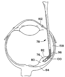
funnel 94, as generally indicated at 100. The curvature 100
16
SUBSTITUTE SHEET
94121205 PCTIUS93/08616
of the tubular tip 96 facilitates the manipulation of the
instrument 78 within the eye; particularly the.manipulation of
the instrument to a position between the retina 82 and the
supporting tissue 84 on the curved walls of the eye. The
radius of the curvature 100 of the tubular tip 96 will depend
upon the procedure and the radius of curvature of the host
eye.
The instrument 78 further comprises plunger means 95
to assist the graft 74 through the narrow tubular tip 96. As
shown in Figure 18, the plunger means 85 is preferably a thin
tubular plunger 86 received in the open end 92 of the tubular
body 90 so that relative advancement of the plunger through
the funnel 94 and into the tubular tip 96 with respect to the
tubular body urges the coiled cellular structure 76 through
the funnel of the tubular body and through the tubular tip of
the instrument 78. To reduce damage to the fragile cellular
structure 76 caused by direct contact between the plunger 86
and the cellular structure, the coiled cellular structure is
protected from direct contact with the plunger 86 by a spacer
made from gelfoam 102 or other soft compressible material
which is inserted into the open end 92 of the tubular body 90
prior to the insertion of the plunger. The gelfoam 102 is
guided to lay on top of the coiled cellular structure 76 and
thereby protects the coil from direct contact with the
mechanical plunger 86. Gelfoam is satisfactory because it is
semi-solid and non-toxic. The plunger 86 projects a
sufficient distance from the open end 92 of the tubular body
90 so that the projecting end 88 of the plunger can be
manipulated even when the tubular tip 96 of the instrument 78
is in the eye. The preferred method of operating the
instrument 78 is that once the tubular tip 96 with the coiled
cellular structure 76 therein is properly located within the
subretinal area 80 of the eye, the plunger 86 is manipulated
17
S!lSSTITUTE SHEEP
CA 02158443 2001-12-19
to eject the coiled cellular structure 76 ~trom the tubular tip 96 of the
instrument. While the
plunger 86 provides the greatest control' over the ejection of the volute 76
into the eye, some
caution must be exercised while operating the plunger because of the increased
likelihood of
damage to the volute 76.
Alternatively, the plunger means 85 may comprise means for applying fluid
pressure (not
shown) on the contents of the tubular body 90. In this case, the open end 92
of the tubular body
is connected to a line connected to a source of fluid under pressure. Fluid
can be selectively
supplied via the line to the open end 92 of the instrument 78 to displace its
contents. The fluid
may be viscous, for example a 2 % carboxymethylcellulose, or non-viscous.
Particularly in the
later case, it may be desirable to have gelfoam or some other relatively soft
spacer material
in the tube to act as a mechanical plunger and to separate the fluid from the
cell structure being
implanted. As previously discussed, gelatin is satisfactory to protect the
volute because it is
semi-solid and will dissolve harmlessly if it is ejected from the instrument.
While the use of fluid
pressure as the plunger means 85 significantly decreases the likelihood of
damage to the volute
76, it also results in a significant reduction in the degree of control over
the ejection of the
volute 76 from the instrument 78.
As shown and described in U.S. Patent 5,962,027, numerous features can be
included
with the instrument to facilitate a particular surgery. As shown in Fig. 17,
the instrument may
include a lumen 108 extending generally parallel with the instrument 78. As
used herein, lumen
108 refers to any tube-like vessel, whether separately provided or formed as a
passageway on
the outside of the instrument 78.
18
~O 94/21205 PCT/US93108616
The lumen 108 has a distal end 110 generally adjacent the
tubular tip 96 of the instrument 78, and preferably slightly
advanced relative to the tubular tip. The proximal end 112 of
the lumen 108 is remote from the distal end 110 and may be
S provided with a connector for connection with a source of
. fluid under pressure. Thus, the lumen 108 can eject a stream
of fluid from its distal end 110 to create a fluid space ahead
of the instrument 78. The tubular tip 96 of the instrument 78
follows generally in the path opened by the fluid thus
minimizing direct contact of the instrument and the eye
tissue. The distal end 110 of the lumen 108 may be beveled to
facilitate the advancement of the instrument 78, particularly
at times when fluid is not being ejected from the lumen. The
end 110 is preferably beveled at about 45a. The fluid ejected
from the lumen 108 may be a saline solution, or some other
fluid that will not harm the delicate eye tissues. Various
substances, such as anti-oxidants, anti-inflammatories,
anti-mitotic agents and local anesthetics can be provided in
the fluid for treatment of the eye or implanted tissue.
Depending on the type of surgery, the instrument may
also include a fiber optic filament (not shown) extending
generally parallel with lumen 108, and positioned between the
lumen and the tubular body 90. The fiber optic filament
facilitates the manipulation of the instrument 78 and the
proper placement of the graft 74 in two ways: a light source
can be provided at the proximal end of the fiber optic
filament so that the filament provides light, at the tubular
tip 96 of the instrument 78, to facilitate the visual
observation procedure through the pugil; alternatively, a lens
could be provided at the proximal end of the fiber optic
filament so that the filament can be used for direct
observation at the tubular tip of the instrument.
Additionally, the fiber optic filament could allow for
19
S!lBSTPTUTE SHEET
WO 94!21205 " PCTIUS93108616
laser-light cautery to control subretinal bleeding.
The instrument 78 can Further include a second lumen
(not shown) extending generally parallel with first lumen 108,
and positioned between the lumen 108 and the tubular body 90.
The second lumen allows for the aspiration of material from
'the tubular tip 96 of the instrument 78. The proximal end of
the lumen can be connected to a source of suction so as to
remove excess fluid and debris.
The instrument 78 can further include a pair of lead
wires (not shown) terminating in an electrode at their distal
ends. The electrode allows for cauterization of blood
vessels. The proximal ends of the leads can be connected to a
source of electrical power to seal broken blood vessels. It
is possible to incorporate the leads onto the wall of the
tubular body 90 of the instrument 78.
Of course, two or more of the features described
with respect to the alternate embodiments could be combined,
as necessitated by the particular circumstances.
The method of transplanting a volute 76 into the
subretinal area of an eye comprises assembling a
transplantable material such as retinal pigment epithelial
tissue, choroidal tissue, Bruch's membrane and/or retinal
cells 54 into a graft 74 as previously described. It will be
understood that the transplantable material may be formed into
a graft without the gelatin carrier sheet and still be within
the scope of the present invention. Preferably, however, the
graft is assembled with a carrier sheet 70. The
transplantation method provides for the graft 74 to be placed
in the instrument at the open end 92 of the tubular body 90
with the graft 74 engaging the interior wall of the tubular
body. The graft 74 is placed, one end 73 first, in the open
end 92 of the tubular body 90 so that the carrier 70 will be
coiled with the outer segments of the photoreceptor layer 54
SUBSTITUTE SHEET
94/21205
PCT/US93108616
facing toward the outside of the convolutions 77 of the
resultant volute 76 and so that the volute will uncoil in said
subretinal area 80 with the outer segment of the photoreceptor
layer facing toward the pigment epithelial layer 84 of Che
host eye. The tubular tip 96 of the instrument 78 is capped
118 and the tubular body 90 is filled with viscoelastic fluid
120 which facilitates the graft's progression into the tapered
passage or funnel 94. The graft 74 slidably proceeds into the
funnel 94 engaging the progressively narrowing tapered surface
causing thegraft to progressively coil. As the interior
walls of the funnel 94 narrow sufficiently to cause the sides
72 of the carrier sheet 70 to make contact, one side 72 of the
sheet 70 slides underneath the other side of the carrier sheet
due, in part, to the carrier's skived sides. The skived sides
72 prevent any buckling of the carrier sheet 70 as the side
edges make contact. In the alternative embodiment shown in
Fig. 21, as the interior walls of the instrument 78 narrow
sufficiently to cause the sides 72 of the graft 74 to be in
proximity to each other, ramp 99 directs one side underneath
the other side to begin the coiling of the volute 76. At some
point in the funnel 94 the convolutions 77 of the coil 76 are
sufficiently constricted so that the viscoelastic fluid 120
can no longer force the coil through the funnel. A gelfoam
spacer 102 is placed on top of the coil 76, a bulb 104 is
placed on the open end 92 of the instrument to create a vacuum
so that the fluid 120 and the volute 76 remain in the
instrument 78, and the cap 118 is removed from the tubular tip
96 of the instrument 78. A syringe 106 can be inserted
through the bulb 104 to inject more fluid 120 as required.
The plunger 86 is inserted through the bulb 104 into the open
end 92 of the tubular body 90 and manipulated to be in contact
with the gelfoam spacer 102. The plunger 86 is carefully
advanced to force the graft 74 through the funnel 94 to
21
SUBSTITUTE SHEET
WO 94/21205 PCTIUS93108616
2~~544~
further coil the graft into a volute 76 and into and through
the curved path 100 of the tubular tip 96.
The host eye is prepared so as to reduce bleeding
and surgical trauma. A scleral pars plans-surgical approach
to the subretinal space is preferred (Fig. 20), but other
approaches, such as transcorneal and traps-scleral, may be
used. A small incision (about 0.75 mm - 2.0 mm) is made in
the pays plans large enough to insert surgical instrument 78.
Following vitrectomy, the eye can be cooled by infusion of
cooled balanced salt solution through a second pars plans port
into the vitreal cavity of the eye 112, to avoid dissolution
of the carrier sheet 70 of the volute 76 during the surgical
procedure. A portion of the retina 82 at the site of
implantation is raised away from the pigment epithelial cell
lining 84 by making an incision 122 in the retina and infusing
balanced salt solution in the subretinal area to form a bleb
80 at the implantation site of the retina 82. If the
instrument 78 includes a lumen 108, the retina 82 may be
detached by the gentle force of a perfusate such as a
saline-like fluid, carboxymethylcellulose, or 1-2% hyaluronic
acid ejected from the lumen to create a bleb 80.
Advantageously, the fluid may additionally contain-
anti-oxidants, anti-inflammation agents, anesthetics or agents
that slow the metabolic demand of the host retina 82.
The instrument 78 with the volute 76 at its tubular
tip 96 is inserted through the pars plans port, through the
vitreal cavity and into the subretinal space. As illustrated
in Fig. 20, the instrument 78 is then manipulated so that the
edge 98 of the tubular tip 96 is in line with the incision 122
of the bleb 80. The entire tip 96 of the instrument 78 is
inserted in the bleb 80 and the volute 76 is ejected by
carefully advancing the plunger. The volute 76 is ejected
from the beveled edge 98 of the tubular tip 96 and uncoils
22
SUBSTITUTE SHEET
CA 02158443 2001-12-19
under its inherent uncoiling memory as it is ejected from the bevelled edge so
that the outer
segments of photoreceptor layer 54 is ftcing the pigment epithelial layer 84.
If the volute 76
does not uncoil entirely, micro picks can be used to completely uncoil the
graft 74.
The bleb 80 is then deflated by evacuation of fluid within the bleb or by
tempanade so that
the graft 74 is held in a sandwich-like arrangement at the desired position by
the retina 82 and
pigment epithelial cell lining 84. The incision 122 of the bleb 80 may be
closed cauterly. The
gelatin carrier sheet 7U dissolves when it reaches normal body temperature.
The edges of the
scleral incision are abutted after removal of the forceps and sutured using
standard opthamalogic
procedures.
As shown and described in U.S. patent 5,962,027, a traps-choroidal, scleral
and corneal
surgical approach may be used as an alternative to the pars plana approach
described above.
Except for the point of entry, the surgical technique is essentially the same
as outlined above.
In view of the above, it will be seen that the several objects of the
invention are achieved
and other advantages attained.
As various changes could be made in the above surgical instruments,
compositions of
matter and methods without departing from the scope of the invention, it is
intended that all
matter contained in the above description or shown in the accompanying
drawings shall be
interpreted as illustrative and not in a limiting sense.
23