Note: Descriptions are shown in the official language in which they were submitted.
CA 02160507 1999-07-20
1
OSTEOSYNTHETIC LONGITUDINAL ALIGNMENT AND/OR FIXATION DEVICE
FIELD OF THE INVENTION
This invention relates to an osteosynthetic longitudinal
alignment or fixation device.
BACKGROUND OF THE INVENTION
Intramedullary nails have found widespread use in
osteosynthesis. Since the first application of this method by
KUNTSCHER, intramedullary nails have been developed to include
a wide range of indications (locking, gamma nail, reconstruc-
tion nail).
Despite the wide range of development, the basic concept has
remained unchanged. It involves introducing a hollow or solid
cylinder into the intramedullary cavity of a tubular bone. In
early days nailing of the femur was predominant, but with time
this type of osteosynthesis has been applied to all major long
bones. Because the intramedullary canals of the various long
bones have been prepared by reaming out the medullae with
reamers no particular attention has been paid to nail
configuration or profile.
Conventional intramedullary nails are typically rigid, stiff
and relatively straight. As a result, the insertion points of
the nail into the bone are usually fixed and are determined by
CA 02160507 1999-07-20
2
the geometries of the nail and the medullary canal. However
the points selected for insertions of rigid intramedullary
nails may have drawbacks for reasons of anatomy and
accessibility:
- significant muscles coverage over insertion site may make the
insertion point difficult to approach surgically and may, as
well, lead to soft tissue damage as the surgeon tries to
approach the insertion site;
- possible interference with joint areas;
- possible damage to the opposite cortex caused upon entry of
the rigid nail tip into the medullary canal;
- risk of damage to bone at the insertion site due to excess
stress during insertion of nail (caused by too rigid nails);
- the insertion site and nail path created by a rigid
intramedullary nail in a long bone may interfere with the
growth plate in your patients.
An intramedullary nail having a flexible conformation which can
be stiffened after insertion of the nail into the medullary
cavity is disclosed in the publication SU 1111-748-A, published
September 1984. The drawback of this nail lies in the fact that
its single segment has end teeth and knurled surfaces forming
pairs of locking joints so that upon stiffening the nail takes on
the shape of the intramedullary cavity irrespective of the
possible presence of a displaced fracture.
CA 02160507 1999-07-20
3
Another aspect is the geometry of the nail cross section. If
one is concerned with causing the least damage to the
intramedullary cavit~~ and preserving blood circulation in the
bone, the nail cross section has to be taken into consideration
more seriously. This is particularly true for the nailing of
the humerus. The intramedullary cavity of the humerus is not
circular over its entire length, and therefore the axially
off-set insertion of a nail with a circular profile is not
recommended .
SUM'~SARY OF THE INVENTION
The present invention is designed to overcome foregoing
problems by providing a fixation or alignment device,
particularly an int.ramedullary nail, which is capable of
assuming a flexible mode in which it is more easily adapted to
insertion or positioning in or adjacent the bone to be treated
and a rigid mode, in which it provides the desired support.
Specifically, the invention provides an osteosynthetic fixation
or alignment device comprising an upper end segment, a lower
end segment and a plurality of intermediate segments, each of
said segments having' upper and lower ends and a longitudinal
axis, connecting means joining said segments end to end and
tightening means for pressing said segments together into a
rigid configuration, the abutting ends of at least two of said
segments being shaped so that when tightened; the device
assumes a predetermined shape.
~1~~~~7
4
An intramedullary nail according to the invention can be
inserted in its flexible state through insertion points which
are more accessible in terms of soft tissue coverage and
over-all location. The insertion point is not fixed and can be
chosen according to anatomical factors so as to avoid problems
of the traditionally rigid intramedullary nails leading to soft
tissue damage and interference with joints. As the nail is
inserted into the medullary canal, it bends to fit into and
conform to the canal.
In a nail according to the invention the segments can either be
directly linked together, e.g. by special laser-cut geometry of
their ends, springs etc., or alternatively the segments can be
separate pieces connected by means of another separate part,
e.g. by a cable, wire or similar connecting device.
A principal advantage of a nail according to the invention lies
in the fact that it can be stiffened to a pre-determined shape
and not necessarily to the configuration which the nail has
temporarily adopted upon insertion in the medullary cavity.
Thus the bone fragments may be forced to conform to the
pre-determined shape of the stiffened nail and to become
aligned as desired. In this way a displaced fracture can be
corrected.
CA 02160507 1999-07-20
Further advantages oi° devices according to the invention are
the following:
- The insertion pointy is not fixed and can be chosen according
to anatomical factors so as to avoid soft tissue damage and
interference with joints and growth plates;
- anterograde and retrograde approach may both be possible;
- there is less risk: of damage to the bone at the insertion
4point and at the inner cortex during insertion;
- it may be used on young patients by simply avoiding the
growth plates during introduction and insertion of the nail
into the medullary cavity.
While one of the principal applications of the invention is as
an intramedullary na~.l, the invention can also be applied to
extramedullary devices, e.g. bone plates, longitudinal rods for
spinal fixation systems, longitudinal bars for external
fixation apparatus and similar osteosynthetic devices where it
is desirable to have a longitudinal element which is flexible
during anchoring to the bone but which can be reversible
stiffened at any moment to take a pre-determined shape.
BRIEF DESCRIPTION OF Z'HE DRAWINGS
The invention will be further described with reference to the
accompanying drawings in which:
Fig. 1 is a perspective view of a nail according to the
invention in the flexible state;
Fig. 2 is a perspective view of the nail according to the
invention in the rigid state;
6
Fig. 3 is a perspective view of the upper end segment of
the nail according to Fig. 1;
Fig. 4 is a top plan view on the segment according to Fig.
3;
Fig. 5 is a bottom plan view on the segment according to
Fig. 3;
Fig. 6 is a perspective view of the first intermediate
segment of the central portion of the nail adjacent to the
upper end segment, of the nail according to Fig. 1;
Fig. 7 is a top plan view on the segment according to Fig.
6;
Fig. 8 is a bottom plan view on the segment according to
Fig. 6;
Fig. 9 is a perspective view of the second intermediate
segment of the central portion of the nail according to
Fig. 1;
Fig. 10 is a top plan view of the segment according to
Fig. 9;
Fig. 11 is a bottom plan view on the segment according to
Fig. 9;
Fig. 12 is a perspective view of the lower end segment of
the nail according to Fig. 1;
Fig. 13 is a top plan view on the segment according to
Fig. 12;
Fig. 14 is a bottom plan view on the segment according to
Fig. 12;
Fig. 15 is an enlarged detail of Fig. 14;
CA 02160507 1999-07-20
7
Fig. 16 is a perspective view of a spinal fixation device
according to the invention;
Fig. 17 is a perspective view of another embodiment of a
nail according to the invention in the flexible sate;
Fig. 18 is a perspective view of the nail of Fig. 17 in
the stiffened state;
Fig. 19 is a side view longitudinal section of the upper
end segment of an ano><her embodiment of a nail according
to the invention;
Fig. 20 is a longitudinal cross section of the upper end
segment of Fig. :L9 in a flexible state; and
Fig. 21 is a longitudinal cross section of the upper end
segment of Fig. :19 in a stiff state:
DETAILED DESCRIPTION C)F THE INVENTION
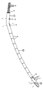
Referring to Figs. 1 <~nd 2, an intramedullary nail according to
the invention comprisE~s an upper end segment 1, a lower end
segment 3 and a central portion 2 comprising a plurality of
longitudinally arrangesd intermediate segments 4.
As can be seen from Figs. 3 - 5 the upper end segment 1
comprises a hollow tube having a bend 5 in order to better
conform to the anatom:ical situation. In the lower part of the
segment 1 a wire 6 :is fixed in a rotatable nut 7. Nut 7 is
seated on a retaining nut 25, inserted in a threaded socket at
the bottom of a channel 9 which extends through the upper end
segment 1.
~~6~~~~
8
Referring to Figs. 6-14, each of the intermediate segments 4 is
formed with a hole or channel 10. The wire 6 extends through
these channels and, as shown in Fig. 15 is anchored in the
lower segment 3 by any suitable means; as for example by a
suitable adhesive or by threading the socket with a thread
having a hand selected appropriately with respect to the hand
of the threads in nut 7. Thus when nut 7 is rotated, as by
means of a suitable tool inserted in hexagonal socket 8, wire 6
is drawn upwardly through the central opening 11 of nut 7,
thereby exerting a compressive force on the segments 4, pulling
them together to adopt a rigid configuration.
The end portions 19 of said segments 4 abutting against each
other are designed in such a way, e.g. by sloping the surfaces
of the contacting ends, that the device - when it is tightened
to its rigid conformation - adopts a pre-determined shape. In
order to prevent rotation of the single segments 4 with regard
to each other (which would render alterable the pre-determined
configuration) the lower surfaces of the segments are provided
with projections 20 and the upper surfaces with corresponding
slots or channels 21.
As shown in Fig. 12 and 14 the lower end segment 3 is provided
with essentially longitudinal cut-outs 12 with sharp edges.
This measure confers the additional function of a manual reamer
to the device.
21~~~~~
9
As shown in Fig. 4 upper segment 1 is further provided with a
proximal locking hole 13 and a proximal locking slot 14, and
segment 3 (Fig. 12) is provided with two distal locking holes
17, to receive locking bolts or pins (not shown).
The segments of this device according to the invention may also
be provided with holes 16 running generally parallel to the
longitudinal axes of the segment. These holes 16 accommodate
locking wires 15. The number and arrangement of the holes and
wires 16, 15 can vary; preferably four wires, symmetrically
arranged are used. The distal tip of the wire which is to be
driven into the bone is rounded as shown in Fig. 2. Locking
wires such as wires 15 can be used along with locking bolts or
pins.
Although the cross section of the segments is shown as
circular, it may be given any desired shape; for example it may
be flattened or oval in shape. The segments may take the form
of polyhedrons, for example prisms. The segments may have a
clover leaf, triangular, square, rectangular or asymmetrical
cross-section. In certain cases one or more of the segments
may be given a helical configuration.
In place of the simple wire shown in the drawings, a loop may
be formed, running the wire 6 out through an opening (not
shown) in the lower end segment 3 and back through a similar
opening to form a loop at the end of the nail which may be used
to engage a securing bolt in the manner described in U.S.
Patent No. 5,034,012. The return end of the wire is carried
upwardly and secured in nut 7.
21~~~~'~
The way in which the invention may be used is believed clear
from the foregoing description. However, purely for
illustration, its use as an intramedullary nail in the
treatment of a fracture of the diaphysis of the humerus will be
described.
The fractured bone is first aligned sufficiently so that the
medullary canal of the main proximal fragment is roughly
aligned with the medullary canal of the main distal fragment.
This ensures that device which is inserted through the first
main fragment finds medullary canal of the second main
fragment.
An insertion site is then chosen which is anatomically
desirable so as to avoid interference with joints, growth
plates and soft tissue. At insertion site, a pathway through
skin and soft tissue is created. The underlying bone is
exposed and an opening in the bone at this site through to the
medullary canal is made.
In its flexible state and with its peripheral wires retracted
as shown in Fig. 1, the device is introduced and fully inserted
into the medullary canal through the opening at the insertion
site. The device is then transformed into its rigid state,
while keeping the peripheral wires in the retracted form. This
is done by rotating nut 7 clockwise with a suitable tool (e. g.
a screwdriver with a flexible shaft) which enters proximal part
1 via channel 9. This causes central wire 6 to be pulled into
nut 7, thereby exerting a compressive force on segments 4 which
are pulled together and adopt a rigid position with respect to
each other.
~1~~~~'~
11
To secure the bone fragments to the device so that the bone can
be stabilized, the device can then be locked with bolts
proximally, distally or both if desired. To do this, a locking
bolt is placed through both bone and device (through hole 13,
slot 14, hole 17 or any combination of these three). Precise
aiming through these holes is done either freehand (with the
aid of an image intensifier) or with an aiming device attached
to proximal part 1 of nail.
A space between the two main bone fragments can be reduced by
locking the device with bolts through at least one distal hole
17 in combination with slot 14. After implantation and during
normal function of the arm, compressive forces are applied to
the humerus, thus allowing the locking screw to slide along
slot 14 and causing the fracture to close on its own.
If desired, peripheral wires 15 can be extended out of distal
part 3, as shown in Fig. 2, to stabilize the fragment in
rotation. To handle peripheral wires 15, a suitable instrument
at top of proximal part 1 is used to push or tap peripheral
wires 15 until they protract sufficiently (as seen using an
image intensifier) at other end of bone and into (or at) the
inner cortex.
Excess wires at top of proximal part 1 are cut off. Wires 15
can be cut flush to top end of proximal part 1. The soft
tissue and skin are closed.
When and if it is desired to remove the nail, the wires 15 are
pulled back until the wire ends are positioned inside the holes
16 and do not protrude out of distal part 3.
12
The nail is then made flexible by rotating nut 7
counter-clockwise with a suitable tool which enters proximal
part 3 via hole 9. This causes central wire 6 to be pushed out
of nut 7, thereby releasing the compressive force on segments
4. The nail is pulled out of the medullary canal, even if ends
of peripheral wires 15 have not been retracted into holes 16.
Due to the elastic nature of the peripheral wires 15, there is
a spring effect during removal from the medullary cavity which
causes part of peripheral wires extending (protracting) out of
distal part 3 to deform inwards. This elasticity of wires 15
avoids damage to inner cortex of medullary canal. The soft
tissue and skin are then closed.
As noted above, devices according to the invention may be used
for applications other than intramedullary nailing. A spinal
fracture device is illustrated in Fig. 16. This device
comprises an upper end segment 30, a lower end segment 31 and a
central portion 32 comprising a plurality longitudinally
arranged intermediate segments 33. In addition, the spinal
fracture device comprises small wedge shaped segments 34
between the intermediate segments 33. The internal structure
of the segments of the device of Fig. 16 may be similar to that
shown in Figs. 1 - 15, i.e. the upper end segment may have a
nut 35, with an internal opening 37, corresponding to the nut 7
of Fig. 4 and a wire or cable 36 may extend through the
intermediate segments to the lower end segment 31 for
tightening the device in the manner described above in
connection with Figs. 1 - 15. The wedge shape of elements 34
216~~~~
13
leads to a bent configuration of the spinal fixator when it is
tightened by means of rotatable nut 35 and non-rotatable wire
36 fixed to lower end segment 31.
The spinal fixator may also be provided with one or more clips
18 with through-holes 22 for receiving pedicle screws or hooks
to be anchored in the bone.
An alternative embodiment of the alignment or fixation device
of the invention is shown in Figs. 17 - 18. The device of Fig.
17 has essentially the same elements as the device according to
Fig. 1, i.e. an upper end segment 40, a lower end segment 41
and a central portion 42. However in this case the central
portion comprises a hollow tube 43. In place of distinct
segments the tube 43 has a plurality of cuts 23,24. These cuts
run circumferentially for approximately 180° to 350°, typically
300°. A central wire or cable 44 is fixed in lower end segment
41 and is threaded in a nut 45 having an internal opening 46,
in a manner similar to the structure of Fig. 1. Several groups
of cuts may be made having different circumferential positions.
Thus, in Fig. 17 the upper group of cuts 23 is positioned on
the right side and the lower group of cuts 24 is positioned on
the left side of the tube. By this expedient it is possible to
confer a pre-determined configuration to the device which it
will assume upon tightening in a manner similar to that of the
embodiment of Fig. 16, i.e. by rotating nut 44 from the outside
with a suitable wrench. The pre-determined shape of the
stiffened device is represented in Fig. 18, where the upper and
lower parts are bent in different directions due to the
21~~~v~
14
different orientation of the cuts 23 and 24. By applying
additional groups of cuts with selected orientations, it is
possible to obtain a wide range of pre-determined shapes of the
device upon tightening.
An alternative embodiment of the tensioning mechanism of an
alignment or fixation device of the invention is shown in Figs.
19 - 21. In this embodiment the upper end segment 50 holds a
central wire 54 of a fixed length and which cannot rotate. It
is threaded into one side of a flat tension block 51 so that,
when the tension block 51 and central wire 54 are pulled
towards the nail tip, there is a fixed amount of total
longitudinal play between the nail segments, allowing the nail
to be flexible. In the flexible state, as shown in Fig. 20, the
flat tension block 51 and central wire 54 are free to move
longitudinally in the open slot 52. Open slot 52 corresponds
to the two threaded bores 53,55 in the upper end segment 50. To
stiffen the nail, near cortex is first drilled to same diameter
as the tension screw 60 (Fig. 21). Transverse tension screw 60
is then placed through the bone hole, is screwed into the
threaded bore 55 on the near side upper end segment 50 of the
nail, contacts angled surface 56 of tension block 51, pushes
tension block 51 towards the proximal part of the nail (left)
by a fixed distance equal to the play between the segments, and
is then screwed into the threaded bore 53 on the far side of
the upper end segment of 50 the nail until it reaches the outer
surface of the nail. As the intervals of the middle segments
(being essentially the same as for the nail of Fig. 1) are
216~~~~
reduced to zero, the adjacent surfaces of the nail segments
come into close contact and cause the nail to be stiffened.
Fig. 21 shows the final position of the tension screw 60, which
is unicortical.
The central wire can have a circular cross-section, as shown in
the above examples, but can also be realised with a polygonal,
hexagonal or square cross-section which eliminates the need for
V-tabs on the segments for alignment.
In using the device according to the invention as a spinal
fixator, the following technique may be employed, illustrating
correction of a spinal fracture or deformation using a dorsal
approach.
First steps are taken to ensure that pre-determined shape of
the stiffened device corresponds to desired shape of the spinal
column. For the device shown in Fig. 16, this is done by
inserting the appropriate number and shape of wedges 5 between
the segments 6. For the device shown in Figs. 17 and 18, the
cuts 23 and 24 must result in the appropriate shape when the
device is compressed. For both devices, the appropriate number
of clips 18 must be put on the device and located in the
appropriate positions along the length of the device.
The skin is then opened at the spinal column dorsally and soft
tissue cleared away if necessary. The device, in the flexible
state (e.g. Fig. 17) is placed in the desired position on the
spinal column and secured to the spinal column as by placing
screws through holes 22 of clips 18 and into the pedicles of
16
the vertebral bodies. Since the device is in the flexible
state, all screws should reach the pedicles by simple
deformation of the device in the appropriate direction.
The device is stiffened by rotating the nut clockwise with a
suitable tool (e.g. a wrench). This causes the central wire to
be pulled up into the nut, thereby exerting a compressive force
on intermediate segments (Fig. 16) and between cuts 23 and 24
(Figs. 17, 18). During stiffening, the device takes on a
pre-determined shape, corresponding to the normal anatomy of
the spinal column and, since the device is secured to the
spinal column, the spinal column also adopts this
pre-determined anatomical shape.
The devices according to the invention may be made of any
appropriate material, depending on the purpose to be served.
They may be made of metals, for example an appropriate
stainless steel or titanium or of plastic or plastic-composite.
While the foregoing description and drawings represent the
preferred embodiments of the present invention, it will be
obvious for those skilled in the art that various changes and
modifications may be made therein without departing from the
true spirit and scope of the present invention.