Note: Descriptions are shown in the official language in which they were submitted.
WO 94/25093 ~ ~ ~ PCT/US94/04526
- 1 -
URETERAL STENTB. DRAINAGE TUBES AND THE LIRE
Field of the Invention
This invention relates to ureteral drainage
stents. It also has potential application to other cases
where it may be important to simultaneously realize small
catheter size, special end tip characteristics and
ability to pass over a relatively large guidewire. The
invention also relates to marking medical articles.
Backctround of the Invention
When a patient has an obstruction of the ureter,
it is common to relieve the obstruction with a ureteral
stent to enable urine to pass from the kidney to the
bladder. Typically, the stmt extends from the kidney to
the bladder. In some cases, the stmt has a retention
configuration, such as a pigtail, at its ends in the
kidney and the bladder.
A common case of ureteral obstruction is the
ureteral stone, while cancerous tumor or a feature of the
anatomy that allows ureter kinking can also produce
ureteral obstruction.
Another occasion for use of a ureteral stent is
after lithotripsy has been performed to break up a stone.
A stent may be placed to allow fragments of stone to pass
from the body and enable the ureter to heal.
Ureteral stents may be introduced to the body
either percutaneously in an antigrade fashion, using, for
example, an adaptation of the Seldinger technique, or
cystoscopically in a retrograde fashion. The stents
positioned in the bladder through a cystoscope are passed
into the ureter using direct vision through the endoscope
positioned in the bladder. For thus placing the stent
there are two common methods. One is the so-called over-
' the-wire placement method. A guidewire of sufficient
stiffness and maneuverability is inserted into the ureter
WO 94/25093 ~ PCT/US94/04526
r
- - 2 -
under endoscopic guidance. When access past the ureteral
obstruction to the kidney is achieved, the stent is
introduced to the ureter over the wire by a pusher
catheter acting on the trailing end of the stmt. The
common guidewire size that urologists prefer is .038 inch
diameter, selected to be stiff enough t~i~negotiate past
the obstruction, but small enough to enable passage of a
small stent over it.
The second common endoscopic placement method for
ureteral stents, which omits the prior step of placing a
guidewire, may be used where no large obstruction is
indicated. In this method, the guidewire is inserted
through the stent only until it is flush with or within
the tip of the stent. A pusher is again inserted behind
the stmt on the guidewire and is locked to the guidewire
with a locking hub (e. g. Speed-Lok~ product available
from Boston Scientific Corporation, Watertown, MA). The
assembly is then pushed by the pusher catheter acting on
the trailing end to enter the cystoscope and then the
ureter.
The choice of technique is based on physician
preference and evaluation of the patient. For instance,
if the obstruction is small, the physician may first try
to use the retrograde technique in which the wire does
not extend beyond the entry end of the stent for saving
time and cost. But if that technique is unsuccessful,
the stmt is withdrawn and the guidewire is inserted
retrograde. As the wire is much smaller in diameter than
the stmt it can more easily be negotiated past the
obstruction. When the wire is successfully placed, the
stent is passed over the wire. The over-the-wire
technique is usually more reliable and less traumatic to
the patient, and also may lessen the risk of ureteral
perforation or puncture.
CA 02160699 2001-09-26
- 3 -
It is preferable for the hospital to be able to
stock one stent unit to be used in both retrograde
placement techniques as it involves less inventory cost.
Also a dual-use stent allows the physician to have both
options when he opens the package. It is therefore
highly desirable that a single stent be capable of both
types of placement and capable of using a guidewire as
large as the common 0.038 inch guidewire.
It is likewise desirable for a stent to carry
markings of its identity so that, for instance, a
physician, when withdrawing a used stent, can determine
e.g. its length, French size and style, to be able to
assuredly select a replacement stent of identical
character.
Furthermore, it has been found that by using a
hydrophilic, dissolving tip on the end of a ureteral
stent, significant advantages can be obtained, as are
disclosed in U.S. Patent No. 5,049,138.
In this case two very
dissimilar materials are employed with two different
desirable attributes. The dissolvable tip is very rigid
and hydrophilic (lubricious) which both assist in non-
traumatic placement. The body of the catheter to reside
in the ureter is very soft and pliable for patient
comfort and for avoidance of trauma over the duration of
its residence in the ureter. By being dissolvable, the
hydrophilic entry tip disappears after it has been useful
in the placement of the softer material in the ureter.
The dissolution of the tip provides a larger passage for
improved drainage.
In respect of long-term patient comfort, ,
peristaltic action of the ureter constantly occurs, in
normal function. This produces forces and sensations
associated with attempted expulsion of the stent. To
diminish these tendencies and improve patient tolerance,
WO 94/25093 PCTIITS94/04526
- 4 -
it is highly desireable that the stent be as small in
diameter as will perform the drainage task. Also, the
smaller the stmt, the easier it is to pass through the ,,
endoscope and pass the ureteral obstruction.
Heretofore, however, it has not been pdssible to ,
put a dissolving or hydrophilic tip on a stet of the
desired small 6 French size, while having~.~lie capability
to place the stent over the widely preferred wire size of
.038 inch diameter. Such combination has appeared
unachievable because of the dimensional characteristics
and requirements of the components.
Summary of the Invention
It has been realized that, in contexts where small
size of endwise-insertable tubular catheters or stents
15' may be deemed of critical importance, that nevertheless
using a slightly enlarged entry tip can provide a
substantial overall benefit, by enabling use of a
separately fabricated entry tip member, the enlarged size
accommodating sleeve-type interconnection between the
parts, the entry tip member providing desirable entry
qualities such as relative rigidity, hardness, or low
friction surface in the tip region, or other qualities
such as dissolvability; on balance such desirable entry
quality or qualities are found capable of off-setting any
undesirable effect of the enlarged entry size, and
provide an over-all improved tubular catheter or stent.
It has been discovered that by making a ureteral
stmt of a small tubular size, e.g., 6 French, but
enlarging the entry end of the stent tube, a dissolving
tip of satisfactory strength and dimension can be secured
in the tube and a bore can be incorporated in the tip
enabling passage of an .038 inch guidewire having the '
desired stiffness characteristics.
CA 02160699 2003-10-02
-4a-
This invention provides a method of forming a stent comprising: providing a
tube
of nominal dimension having an enlarged end, the tube comprising a first
thermo-plastic
material having a first melting point; providing a preformed tip member
comprising a
connector shank, the preformed tip member comprising a second thermo-plastic
material
having a second melting point, wherein the first melting point is lower than
the second
melting point; inserting the connector shank into the enlarged end of the
tube; and
thermo-forming the enlarged end around said connector shank in tight,
retaining, intimate
engagement with the connector shank. In the aforementioned method, the tip
member
may be comprised of hydrophilic material that readily dissolves when contacted
with
body fluids.
This invention also provides a medical device comprising a main catheter body
of
flexible material having an internal bore of diameter closely corresponding to
the outer
diameter of a predetermined guidewire with which said main catheter body is
constructed
to be used, the internal surface of said main catheter body being exposed to
directly
engage said guidewire, and a tip member at the distal end of said main
catheter body, said
tip member comprised of hydrophilic material that readily dissolves when
contacted with
body fluids to which said medical device is intended to be exposed and having
a through-
bore substantially corresponding to the internal bore of said main catheter
body, said tip
member having two portions, an end portion constructed to serve as the distal
end of said
medical device and an integral connector shank portion smaller in outer
diameter than
said end portion and constructed to be securely engaged within a distal end
portion of the
main catheter body, characterized in that said distal end portion of said main
catheter
body is larger in outer diameter than the general outer diameter of the main
catheter body,
said distal end portion of said main catheter body being disposed about and
secured to the
exterior of said connector shank portion of said tip member and, when said tip
member is
dissolved, providing an enlarged entry to said main catheter body for
facilitating entry of
fluid and debris.
This invention also provides a medical kit for ureteral drainage, comprising:
the
aforementioned medical device, a guidewire of selected flexibility sized to
pass through
said medical device, and a pusher catheter, for locating said medical device
in the ureter
by pushing said medical device over said guidewire.
WO 94/25093 PCT/US94/04526
- 5 -
Stents according to the invention incorporate a
tip of sufficiently large size that the tip can be
reliably manufactured and secured to the stent body.
In preferred embodiments, the dissolvable tip is
polyvinyl alcohol containing glycerin as a plasticizes.
Such a material is high in viscosity and very difficult
to mold. The present invention enables meeting the wall
thickness constraints for moldability and strength while
accommodating a through-hole that enables passage of the
.038 inch wire. In this way a sufficient tubular wall
thickness in the connection region, e.g., .008 or .010
inch, can be achieved to enable the entry tip member to
be reliably molded and secured in a pre-enlarged end of
a
6 French catheter of conventional soft material.
In preferred embodiments the stent is constructed
by forming an enlarged end on a soft stent tube,
inserting a connector shank of the separately formed tip
member, and forming the tube material about the shank.
Preferably thermo-forming of the tube material is
employed for both preforming and post-insertion tasks.
While the invention has been occasioned by the
need for an improved small diameter (e. g. 6 French),
over-the-conventional-wire (e. g. .038 inch) ureteral
stent having a dissolvable tip, it is realized that the
present invention has broader potential applicability for
realizing two part stents and catheter constructions
having severe size constraints in which the entry tip can
provide desirable properties different from the main body
of the stent or tube.
Brief Description of the Drawing
Fig. 1 is a view of the preferred ureteral stent
according to the invention;
Fig. 1a is another view of the stent (rotated 90
out of the page) in Fig. 1; and
WO 94/25093 ~ ~ PCT/US94/04526
- 6 -
Fig. 2 is an enlarged longitudinal cross-section
taken on line 2-2 of Fig. 1.
Description of the Preferred Embodiment r
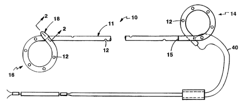
In the preferred embodiment, the stent 10 is a
tubular member of selected thermo-plastic polymer
selected for suitable flexibility. Examples are low
molecular weight urethane, the material. C-Flex' available
from Concept Polymers of Clearwater Florida and
Percuflex'~ stents available from Boston Scientific
Corporation. The main body 11 of the stent is of 6
French outer diameter consistently throughout its length,
except for a short tip portion 18 at the kidney "pigtail"
retention formation. The tip portion of the stent, about
1 cm length, is enlarged to approximately 7.5 French.
The tip formation is formed partly by bullet-shaped
leading tip 22 of hydrophilic, dissolvable tip member 20
and partly by the enlarged portion 24 of the stent tube
that lies over and securely engages the barbed connector
shank portion 26 of the tip member. The tip member is on
the distal end of the stent which is introduced first
into the body.
In the preferred embodiment, the stent has ends
shaped by thermal methods into circular pigtail retention
formations 14 and 16 and is between 10 to 30 cm in length
between the pigtail formations, depending upon patient
size. It has drainage holes 12 throughout its length.
The drainage holes are spaced approximately 1.5 cm
apart over the length of the main body 11 of the stent,
these lying in a spiral pattern down the length of the
body. On the pigtail retention formations, the holes are
spaced 1.5 cm, in line. The stmt has a placement
marking 15 at its bladder pigtail end that is used for
visualization by the physician to know when the
appropriate length of stmt has been inserted into the '
ureter. Referring to Fig. la, the stmt also includes a
WO 94/25093 _ PCT/US94/04526
medial line 19 down the spine of the stent, which is used
to orient the pigtails. These and other markings 21,
e.g~ size and manufacturer, may be made by laser scribing
techniques, which are discussed in more detail below.
The dissolving tip placed in the kidney pigtail end of
the stent is made of a thermo-plastic material, e.g.,
polyvinyl alcohol plasticized with glycerin, formed by
injection molding, see the above referenced patent for
details.
In manufacture, the end of the 6 French tubing is
preformed to accept the tip member by heating a teflon
mandrel and pushing it the required distance into the end
of the tube, thereby causing the polymer of the tubing to
flow and stretch to a larger size in this localized tube
region. The tube is then allowed to cool and the mandrel
is removed, with the tube end holding its enlarged
diameter. The shank 26 of the tip member 20 is then
inserted with an interference fit into the end of the
tubing, while a .041 inch diameter wire mandrel is
maintained in the bore of the affected region, i.e. in
the tip of the stent lumen and the tip member. The
united region of the tip member and the stent are then
inserted into a heated mold to displace the thermo-
plastic material of the stent body into tighter
engagement around the barbs of the tip member. The part
is then cooled, and removed from the mold and the wire
mandrel is removed from the stent, allowing the preformed
pigtail to reform to its preset shape. The length of the
enlarged region of the stent tubular body 11 is
approximately 5 millimeters.
In more detail, the final molding procedure is
accomplished with a mold formed by an aluminum block in
which a hole has been drilled, sized appropriately for
the outer final diameter of the enlarged tip portion.
That mold has a tapered lead-in to facilitate placement
WO 94/25093 ~~~~ , PCTlUS94/04526
_ g _
of the tipped stent assembly into the mold. The mold is
heated with RF energy or other means of heating. The
assembled catheter is pushed through this heated mold
bore. Passage end-on through the bore displaces the
thermo-plastic material of the stenthbody and smooths it
out over the length of the retention'barbs. The
effective zone of the mold matches in length the
transition zone of the barbs a distance of approximately
5 millimeters. Because the material flow during this
molding step is in the inverse direction toward the
bladder end of the stent, the extra material is
compressed and formed intimately around the barbs and
around the back of the tip member with no detrimental
mold flash or interruption to the smoothness of the entry
end of the stent.
By having the .041 mandrel in place during this
post connection operation, the lumen opening is
maintained straight and of design diameter in both of the
joined parts.
The melt temperature of the dissolvable material
is much higher than the melt temperature of the very soft
thermo-plastic that is preferred, so that its contour is '
not affected by this heat-molding operation.
After this step no further finishing operation is
required. After the end assembly cools, it is removed
from the mold, the mandrel is removed and the pigtails
are allowed to return to their pre-set shape.
In use, this product facilitates placement into
the body over an .038 inch diameter guidewire as well as
by using techniques in which the guidewire does not
extend beyond the entry end of the stent. By using the
invention it has become possible to incorporate a tip of
dissolving material with its desirable rigid and
hydrophilic features for ease of placement and
tractability past a tortuous obstruction, while in
S WO 94/25093 PCT/IJS94/04526
_ g _
addition enhancing patient comfort by leaving a small
stent in place. During placement, because of its
.. hydrophilic nature, and associated lubricity in the
presence of urine, the tip is found to slide smoothly
through the ureter without causing trauma, despite its
enlarged size. Still the main body of the stent, as
mentioned, is of the preferred small size, 6 French, of
very soft, patient-comfortable material.
In the case of over-the-wire retrograde placement
of the stmt over the .038 inch wire guide, in the usual
way the wire is put up through the ureter, past the
obstruction, and then the stent is passed over the wire
and pushed from its trailing end past the obstruction
with a rigid push catheter or piece of tubing. The rigid
and hydrophilic tip tracks nicely over the guidewire.
Once the stent is in place, the wire is removed and the
pigtails are allowed to reform in both the kidney and the
bladder to retain the stent in place for its useful life.
The dissolving mechanism of the tip material is strongly
activated within minutes after placement and totally
dissolves within two hours, just prior to the anesthesia
from the procedure wearing off. By the time the
anesthesia wears off only a very soft biocompatible
polymer tube of the appropriate small size for comfort is
left in place, and remains there during the time
required. In addition, the stent retains an enlarged
entry region in the place where the dissolving tip
material previously resided. This enlarged entry can
facilitate entry of stone fragments or debris that may be
left from the procedure to assist in their capture and
excretion. The enlarged end also will facilitate greater
flow during the useful life of the stent. The relatively
large diameter of the tube end is of no detriment to the
patient because it lies within the confines of the
WO 94/25093 PCT/LTS94I04526
~~~9
- 10 -
retention pigtail, in the renal pelvis of the kidney that
accommodates such size.
In the second preferred retrograde placement
technique the guidewire is placed through the lumen of
the catheter and aligned flush with the bullet shaped
dissolving tip, to act as a stiffener or~"'straightener to
straighten the stent in the usual way.'.The pusher is
then placed behind the stent and locked to the wire
(Speed-Lok~, Boston Scientific Corporation, Watertown,
MA). The locked assembly is then passed up the ureter as
a complete unit. When pushing the stent in this method,
all of the attributes of the lubricious, dissolving tip
still apply in facilitating entry using the preferred
wire size. Once the stent is in place, the same thing
has been accomplished as before, i.e., the placement of a
small preferred diameter tubing that is very soft and
provides patient comfort for its long-term use.
It has been noted above that during passage of the
relatively large end of the stent in either placement
technique, the patient is under anesthesia and has no
sensation. In fact, this tip is believed to be less
traumatic than the 6 French end of a conventional stent
because the dissolvable material of the tip is
hydrophilic and slippery in the presence of body fluids,
and is hence less likely to cause friction damage to the
soft and vulnerable ureteral tissue. It is noted that
the primary ureteral injury that can occur, ureteral
inflammation, is caused by friction and irritation caused
by sliding a stent through the ureter. Because of its
high lubricity, less frictional damage occurs. The
somewhat increased localized side pressure related to the
somewhat enlarged local end diameter can be accommodated
by temporary stretching of the diameter of the ureter
without damage.
WO 94/25093
PCT/US94/04526
- 11 -
Furthermore, a primary advantage of this invention
is the enablement of placement over the physician-
preferred wire size to reduce the risk of uretsral
perforation. For instance, when being pushed past an
obstruction, in the absence of a wire, the stent tends to
veer off course and the soft spongy ureteral tissue can
be punctured easily. By use of the guidewire, the
present device will track more accurately around the
obstruction and through the ureter without such risk of
perforation. Indeed even if use of this product were
restricted to the over-the-wire mode of introduction, it
would have the virtues of the hydrophilic nature of the
tip and the attendant ease of placement while achieving a
small size of soft stmt material, with eventual
disappearance of the tip to enhance drainage capability.
In regard to a preferred specific embodiment it is
preferable that the nominal bore of the tube and the tip
member be the same, of the order of about .044 inch for
passing an .038 inch wire. To facilitate placement over
that wire one needs such a degree of clearance between
the wire and the actual stent itself. In manufacture,
the two mating parts will achieve an .044 inch dimension
in the large majority of cases. The tolerance direction
for the preferred .004 inch tolerance for the bore of the
tip member is in the smaller direction to ensure good
trackablility of the tip member on the wire and to ensure
that the wall thickness of the shank is sufficient for
manufacturability (mold filling) and strength. Because
of its hydrophilic nature a close-fitting tip member will
not drag excessively on the wire, i.e. not as much as a
hydrophobic material might. Also, since the length of
such close tolerance extends approximately only one
centimeter, much less than the total length of the
product itself, little drag is experienced due to closer
fitting of the tip.
~~.~~a6~~
VVO 94/25093 PCT/US94/04526
- 12 -
In the preferred embodiment, the tolerances for
the .004 inch internal diameter of the stent shaft itself
is chosen in the direction of a larger bore. If slight
variation does occur, it will enhance the drainage
capability of the stent and limit the risk of guidewire
friction that may be achieved in passing the stent over
the guidewire, which can have an overall length as long
as 35 to 45 cm.
Numerous alternative methods can be employed for
forming the end of the stent tube, for receiving the tip
member.
For instance, a mechanical stretching of the tube
can be employed and then relaxation of the tube over the
tip without use of heat. Also technical extrusion
processes can be employed to provide the preformed
enlarged end shape to the tube. For instance during
extrusion of the tube, drawing or stretching and then
periodically relaxing for a short distance and then
stretching again can be employed. The diameter will be
larger at the points of relaxation. The tube can be cut
at these points so that diameter is expanded at that end.
Referring further to the figures a monofilament
suture 40 is attached to the most proximal end of the
bladder coil and to the other end of that suture a piece
of tubing is crimped, which the physician can hold as a
handle. This is useful if the physician inadvertently
passes the stent too far up the ureter and needs to pull
it down or remove it because of complication in the case.
The additional piece of tubing shown half way down the
suture is an attachment collar that is attached to hold
the suture parallel to prevent tangling prior to use.
When the product is removed from the package, the plastic
collar is removed and discarded.
As noted above, the stent that has been described
is constructed to enable passing through the working
WO 94/25093 ! ~ ~ ~ ~ PCT/LTS94/04526
- 13 -
channel of an endoscope. The endoscope enables the
doctor to visualize the stent and its placement.
A:Lthough rigid endoscopes are commonly employed for stent
placement, increasingly in practice, smaller scopes with
smaller working channels are preferred because they can
be passed further up the ureter for diagnosis. The
ability to employ a smaller stent assists in the choice
of a smaller endoscope with smaller working channel. The
lubricity and relative short length of the relatively
large tip member of the present catheter helps it pass
through the relatively small channel.
The stent may be part of a kit, which also
includes the positioning or pushing catheter, and a
guidewire, preferably of .038 inch diameter. Wires of
varying stiffness, from rather flexible to super stiff,
may be used. For example, a .038 inch, stiff wire with a
3 cm flexible tip may be provided. The wire may be a
.038 inch Glidewire~ (Boston Scientific Corporation,
Watertown, MA), which is hydrophilically coated. The
wire may be a .038 inch Lubrigide~ wire (Boston
Scientific Corporation, Watertown, MA), a stainless steel
wire with 3 cm flexible tip and also including a
hydrophilic coating. A 5 French ureteral catheter may
also be included as part of the kit. The ureteral
catheter is a straight piece of tubing 70 cm long, having
inch graduations every centimeter to 50 cm and an
adjustable luer-lock hub. The catheter is used by the
doctor to evaluate and access the ureter prior to stent
placement. The wire is placed in the ureter, followed by
the ureteral catheter, which is used to diagnose the
tract by injecting contrast materials that indicate the
location of obstruction.
(We note that in certain circumstances the entry
end of a ureteral catheter may likewise be provided with
a separately fabricated, entry-facilitating end tip
WO 94/25093 PCT/LTS94/04526
- 14 -
member of slightly enlarged outer diameter to facilitate
the connection, in general manner as described above.)
In some embodiments, the stent can be used with
smaller, e.g. 0.025 inch, guidewires, which may be used
to position an endoscope which accepts a laser fiber in t
one working channel and the guidewire in the other
working channel. After application of laser energy, the
laser and endoscope are removed from the body over the
guidewire, leaving the guidewire in the body. The stent
can then be positioned over the 0.025 guidewire in a
manner similar to that discussed above.
As indicated above, the stmt includes markings,
such as marking 15 for locating the stent within the
ureter and marking 19 down the spine of the stent, which
is used to orient the pigtail in the desired direction.
These markings, as well as others that indicate the size,
length and manufacturer of the stent, can be placed on
the stent using a laser scribing system. The system
(Model 1750 Universal Laser Systems, Scottsdale, AZ)
includes a ND-Yag (50 watt, pulse rate 39,949 per cm,
pulse width 10 microseconds, pen speed 9 cm/sec) laser
and a plotter-positioner that locates the laser energy in
accordance with a computer program that may be downloaded
from, for example, a CAD system, e.g. Autocad~ drafting
system. The tubing to be used in the stent, prior to
forming retention curls or drainage openings, is placed
on the plotter unit using positioning grooves and a
mandrel that keeps the tube straight. The laser scribing
unit is then driven by the program to laser-write the
desired pattern on the tubing. The tubing is then
removed from the system and cleaned with a non-reactive
solvent (e. g. freon or alcohol) to remove loose residue.
In a particular embodiment, the tube (wall thickness
0.015 - 0.030 inch) is formed of Percuflex polymer
(ethylvinyl acetate (EVA)), with a radiopacity enhancing
WO 94/25093 -
PCT/US94/04526
- 15 -
additive, preferably bismuth subcarbonate (30~ by
weight). In another embodiment, the polymer is C-flex'
,
- which includes bismuth oxychloride (30~ by weight) and
colorants as additives (Concept Polymers, Clearwater,
FL). The markings are visible because they are of a
different color, usually dark charred color, than the
tube material. The markings are also relieved into the
surface of the tube. The marked tube is free of toxic
byproducts and compatible for use within the body.
While the laser burns, oxidizes or otherwise
removes the tubing polymer, in some cases, additives
within the polymer matrix enhance the marking effect.
For example, PVA without additive is clear and is not
effectively marked by the laser, while EVA with the above
15' noted radiopacity enhancing additive is white and is
found to be effectively marked by the laser described
above. Other laser and polymer combinations may be used
with other selected additives to enhance the marking
effect. For example, C-flex with the oxychloride
additive noted above can also be marked with a C02 laser.
Marking the stent in this manner is particularly
useful since introduction of another material, such as an
ink, is avoided. Further, the markings are retained even
after the stent has been within the body for an extended
period of time, for example the maximum useful life of
typically six to eight weeks. On removal of the stent,
the doctor can easily determine the size and length of
the stent, and its manufacturer, for selecting and
restenting the patient, without remeasuring the length of
the ureter by fluoroscopy.
These and other embodiments can be constructed
within the spirit and scope of the following claims.