Note: Descriptions are shown in the official language in which they were submitted.
~095/29633 ~ ~ 6 3 ~ 1 S PCT~S95/04776
ULTRASONIC APPARATUS AND METHOD FOR INTRAVASCULAR IMAGING
FIELD OF THE INVENTION
This invention relates to ultrasound imaging
apparatuses placed within a cavity to provide images
thereof, and more specifically, to ultrasound imaging
apparatuses and methods for providing images of a cavity
comprising static and dynamic regions.
BACKGROUND OF THE INVENTION
In the United States and many other countries,
heart disease is the leading cause of death and
disability. One particular kind of heart disease is
atherosclerosis, which involves the degeneration of the
walls and lumen of the artery walls throughout the body.
Scientific studies have demonstrated the thickening of
the arterial wall and eventual encroachment of the
tissue into the lumen as fatty material is built up.
This material is known as "plaque." As the plaque
builds up and the lumen narrows, blood flow is
restricted. If the artery narrows too much, or if a
blood clot forms at an injured plaque site (lesion),
flow is severely reduced, or cut off and consequently
the muscle that it supports may be injured or die due to
a lack of oxygen. Atherosclerosis can occur throughout
the human body, but it is most life threatening when it
involves the coronary arteries which supply oxygen to
the heart muscles. If blood flow to the heart muscle is
significantly reduced or cut off, a myocardial
infarction or "heart attack" often occurs. If not
treated in sufficient time, a heart attack frequently
leads to death.
The medical profession relies upon a wide variety
of tools to treat coronary disease, ranging from drugs
to open heart "bypass" surgery. Often, a lesion can be
diagnosed and treated with minimal intervention through
the use of catheter-based tools that are threaded into
the coronary arteries via the femoral artery in the
Woss/29633 PCT~S95/04776 ~
~ ~ ~ 3 ~ ~ 3 2
groin. For example, one treatment for lesions is a
procedure known as percutaneous transluminal coronary
angioplasty (PTCA) whereby a catheter with an expandable
balloon at its tip is threaded into the lesion and
inflated. The underlying lesion is re-shaped, and
hopefully, the lumen diameter is increased to restore
blood flow.
The practiced method for guiding a catheter during
the performance of procedures such as PTCA has been to
use real time X-ray images. With this method, a
radiopaque dye is injected into the coronary tree in
order to provide a map of blood flow. This technique
facilitates identification by a physician of sites where
blood flow is restricted. After identifying the sites,
therapeutic devices are positioned using a live X-ray
image for guidance in order to treat the lesion(s).
However, the X-ray image does not give information about
the morphology, i.e., form and structure, of the artery.
In the last 5 years, cardiologists have adopted a
new technique to obtain information about the coronary
vessel and to help view the effects of the therapy on
the form and structure of the vessel and not just the
blood flow. This technique, known as Intracoronary or
Intravascular Ultrasound (ICUS/IWS) employs
miniaturized transducers on the tip of the catheter
which provide electronic signals to an external imaging
system in order to produce a two or three-dimensional
image of the lumen, the arterial tissue, and tissue
surrounding the artery. These images are generated in
substantially real time and have a high degree of
resolution. As an improvement over X-ray imaging, the
transducers facilitate the construction of images of the
exact site where the transducers are placed within the
vessel.
Several ICUS/IWS devices are now commercially
available for sale in the United States and other
countries. These devices include a transducer probe
WO 95t29633 ù ~ 2, 6 3 2 1 3 PCT/US95/04776
_
assembly having either a solid state transducer array or
a rotating crystal. The physician is most interested in
identifying the size and shape of the lumen, and any
flaps or tears in the plaque, and these commercially
available imaging devices facilitate the creation of
detailed images of these relatively static features due
to the relatively high frequency of ultrasound that they
employ. Image signals are typically transmitted at
frequencies between 10 and 40 MHz.
However, there is a common problem associated with
these devices operating at such high frequencies. As
the frequency of the ultrasound is raised, the
backscatter from blood increases as the fourth power of
the frequency. At frequencies of around 30 MHz, the
amplitude of the backscatter from blood approaches the
amplitude of the backscatter and reflections from the
arterial tissue. Because of this phenomenon, the image
of the lumen is filled with blood echoes, and it is
often difficult to delineate the blood from the
surrounding tissue. Therefore, this becomes confusing
to the physician wh~ is interested in defining the
lumen.
A common method of detecting blood flow in
ultrasonic systems used outside of the body is the use
of a "Doppler" technique. The Doppler technique
involves the detection of a change in frequency of a
wave due to the reflection of the wave from a moving
target. This technique is well established in radar
literature such as M. Skolnik: "Introduction to Radar
Systems", Second Edition, 1980. The Doppler technique,
and variations of it, have been successfully applied to
ultrasonic scanners used outside the body to provide
color overlay maps of flow on top of grey scale images.
A number of commercial systems utilizing this Doppler
imaging technique are available, and are well known to
those familiar with the state of the art.
w095/29633 - ~ h ~ 1 6 3 ~ 1 3 PCT~S95/04776 '~
~ ,....
However, the Doppler technique has its limitations
when applied to arterial imaging. The Doppler technique
relies upon the existence of a component of flow toward
or away from the direction of the ultrasonic beam
emitted by the transducer. In the case of cross-
sectional arterial imaging, there is little or no
component of flow to which the Doppler effect can be
applied since substantially all flow is in a direction
orthogonal to the ultrasonic beam.
A technique is known which attempts to extract a
flow image from pixel data for a sequence of whole frame
video images containing both flow and static portions.
In this technique, pixel data for several whole frame
video images are obtained over a period of seconds. In
order to gather the data for each of the whole frame
video images, an ultrasound transducer assembly
transmits and receives a series of signals from all
radial regions of the imaged volume in the vicinity of
the transducer assembly. It is important to note that
in gathering the data for the pixel data for a single
whole frame video image, no two transduced echo signals
in the set of received echo signals used to create the
single whole frame video image are received from the
same radial region of the imaged volume.
In this imaging technique, the process of gathering
data for a single whole frame video image is repeated
several times over a period of time of more than one
second in order to obtain pixel data for a series of
whole frame video images from which a single combined
video image is to be created. Thereafter, the
differences between values for corresponding pixel
points within successive whole frame video images are
averaged in an attempt to create a single frame image
based upon the pixel data from the series of whole frame
images. By averaging the differences between
corresponding pixel data between frames, the resulting
image is characterized by attenuation of features of the
wo 95/29633 ~ ~ 1 6 3 2 1 3 PCT/US95104776
~_ 5
image that remain motionless for the entire frame
gathering procedure which lasts on the order of more
than one second. This is entirely unacceptable when one
attempts to image the relatively dynamic vessels near
the heart.
The above described technique, involving the
comparison of the data from sequentially created whole
frame images, represents an attempt to provide an image
of dynamic features in a field of view containing both
static and dynamic features. However, this imaging
terhn;que contains certain inherent limitations which
reduce the utility of this imaging technique when
applied to living vascular imaging in organisms. First,
it takes more than a second (or even several seconds) to
obtain a sufficient number of whole frame images to
carry out the comparison and averaging of corresponding
pixel values. Second, in a pulsatile artery, the vessel
wall and moving intimal flaps are not motionless over a
period of a second and therefore will not cancel out
when the pixel values for corresponding positions in the
whole frame images are compared. Third, cross-sections
of a vessel in which blood flow stagnates provide a
relatively static signal and therefore may be canceled
out along with the rest of the other static portions of
the image.
Additionally, it should be noted that the coronary
tree, which comprises the vessels of primary interest to
cardiologists, is the most rapidly moving vessel
structure within the human body. When ultrasonic images
of coronary arteries are made, the position of the
tissue constantly changes during the data acquisition
period due to the influence of the heart cycle upon the
imaged tissue. Consequently, the image created by the
dynamic vascular tissue will blend with the blood flow
image if the above whole frame comparison technique is
employed.
wossl29633 ~ h 2 ~ S 3 2 i 3 pcT~ssslo4776 ~
Furthermore, the relatively long data acquisition
time reguired for the prior known tpchn;que prevents
visual reproduction of the potentially useful dynamic
information present in pulsatile flow.
S SU~ARY OF THE INVENTION
It is a general object of the present invention to
construct images of blood vessels wherein regions of
blood flow are readily discernable from the vessel wall
and surrounding tissue.
It is another object of the present invention to
provide an apparatus that enables a viewer of an
ICUS/I WS image to easily differentiate between an image
of the blood flow region in a vessel cross-section and a
simultaneously displayed image of the vessel and
surrounding tissue.
It is a related object of the present invention to
display on a video monitor the blood flow region in a
blood vessel in a manner which highly contrasts the
blood flow region from the vessel wall and surrounding
tissue.
It is another object of the present invention to
construct the aforementioned images in a manner that
visually appears to approach real-time imaging.
It is yet another object of the present invention
to provide an adjustable image contrast for the user to
find a maximum contrast between the blood flow region
and the tissue under various circumstances.
The above and other objects are fulfilled in an
apparatus and method for providing an image wherein the
static features of an imaged region are substantially
attenuated by combining a set of echo waveforms for a
region of a cross-section obtained within a time period
less than the minimum time period over which one can
reliably depend on a vessel and surrounding tissue to
remain substantially motionless.
In a flow imaging mode of operation, an ultrasound
transducer assembly emits an ultrasound waveform from
~VO 95/29633 ~, ~ 2 1 6 3 2 1 3 PCT/US95/04776
within a lumen of a vasculature. The ultrasound
waveform propagates through a region within the
vasculature. The emitted ultrasound waveform is
reflected by blood and tissue in the region. The
reflected ultrasound waveform is sensed by the
transducer assembly and converted into an echo waveform.
The above described emitting, sensing and converting
functions are repeated a plurality of times for the
region to obtain a set of echo waveforms for the region.
The resulting set of echo waveforms are combined to
form a modified echo waveform representative of rate of
movement of the blood and tissue in the region.
Portions of the modified echo waveform representing
dynamic regions contain large values while portions of
the modified echo waveform representing static regions
contain small values. Flowing blood is relatively
dynamic, and therefore the portion of the modified echo
waveform associated with flowing blood in the region
comprises relatively large values. On the other hand,
tissue is relatively static, and therefore the portion
of the modified echo waveform associated with tissue
includes relatively small values. The modified echo
waveform is thereafter converted into a first image of
the region. The first image prominently displays areas
within the region containing flowing blood.
In order to better delineate the regions of flowing
blood in a blood vessel, a second image of the region is
generated prominently displaying the relatively static
tissue within the region. Thereafter, the first image
is combined with the second image for simultaneous
display on a video display. In order to enhance the
readability of the combined image, the portions of the
combined image attributable to the first image are
displayed in a distinct manner from the second image.
In an embodiment of the present invention, the regions
of flowing blood are colorized while the remaining
portion of the combined image, including the tissue and
WO 95/29633 r~ h ~ I ~ 3 2 ~ 3 PCT~S95/~776 ~
other static features associated with the second image,
are displayed in black and white.
In a further aspect of the invention, the blood
flow image is colorized in order to enhance the contrast
of the blood flow image when the images are combined to
create a composite image with the second image. The
resulting composite image is displayed on a video
monitor.
Other objects and advantages not explicitly
mentioned above will become apparent from the following
detailed description of the drawings.
BRIEF DESCRIPTION OF THE DRAWINGS
The appended claims set forth the features of the
present invention with particularity. The invention,
together with its objects and advantages, may be best
understood from the following detailed description taken
in conjunction with the accompanying drawings of which:
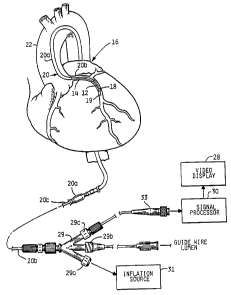
Figure 1 is a schematic dràwing of the ultrasound
imaging system of the present invention and
demonstrating the use of the device to image a coronary
artery;
Fig. 2 is an enlarged and partially sectioned view
of a portion of the coronary artery in Fig. 1 showing
the probe assembly of the ultrasonic imaging device of
the invention located in the catheter proximal to the
balloon;
Figs. 3a and 3b are schematic block diagrams of the
signal processor and video display portion of the
processing and imaging unit of the ultrasonic imaging
device;
Fig. 4 is a flow chart summarizing the steps for
creating a composite flow/static image of a vessel;
Figs. Sa and 5b are representative waveforms of
transduced echo waveforms in analog form resulting from
consecutive excitation signals from a transducer spaced
very close in time;
~ ~VO 95/29633 ~ i~ 2 ~ r' 3 2 1 3 PCT/US95/04776
.,~",_ 9
Fig. 5c is an illustrative waveform demonstrating
the result of adding the waveform illustrated in Fig. 5a
to the waveform illustrated in Fig 5b;
Fig. Sd is an illustrative waveform demonstrating
the result of subtracting the waveform illustrated in
Fig. 5b from the waveform illustrated in 5a;
Fig. 6 is a flow chart summarizing the steps for
acquiring flow image data for an ultrasound imaging
system having a transducer array including 64
transducers which are activated for emitting an
excitation signal in groups of 4 transducers;
Fig. 7 is a flow chart summarizing the steps for
combining the values of two (2) echo waveforms for one
radial section of the ultrasound image;
Fig. 8a is an illustration of a time series square
wave for modulating the received echo waveforms in one
exemplary implementation of flow image filtering;
Fig. 8b is the frequency domain equivalent for the
square wave modulation sequence illustrated in Fig. 8a;
Fig. 9a is an illustration of another illustrative
time series for modulating the received echo waveforms
in another exemplary implementation of flow image
filtering; Fig. 9b is the frequency domain
equivalent for the time series modulation sequence
illustrated in Figure 9a; Fig. lo is a block diagram
of a portion of the signal processor of Figs. 3a and 3b
showing the modifications to the signal processor in
order to carry out filtering by modulating the received
echo signals with the exemplary time series modulation
sequences illustrated in Figures 9a and 9b;
Fig. 11 is a schematic drawing showing an exemplary
scheme for connecting a set of transducers of the probe
assembly to a transmit bus and a receive bus;
Fig. 12 is a schematic illustration of the beam
profile of ultrasonic energy radially propagated from a
set of simultaneously activated transducers;
W O 95/29633 ~ h 2 1 ~ 3 2 i 3 PC~r~US95/04776 ~
'' .,.,_
Fig. 13 is a schematic diagram showing a modified
portion of the image processor illustrated in Fig. 3a to
facilitate applying a plurality of filter waveform
sequences to a set of echo waveforms for a region;
Fig. 14 is an exemplary composite flow image of a
cross-section of a blood vessel including four distinct
flow zones;
Fig. 15 is a flow chart summarizing the steps for
obtaining filtered flow image data for a region of a
vasculature from a plurality of h~n~p~ss filters;
Fig. 16a is a graphical illustration of a set of
four time series filter waveforms for combining the
received echo waveforms in another exemplary
implementation of flow image filtering;
Fig. 16b is the frequency domain equivalent for the
four time series filter waveforms illustrated in Fig.
16a;
Fig. 17 is an exemplary graphical illustration of
an echo signal waveform for a region to be imaged, the
waveform having a relatively dynamic portion from echoes
caused by the blood and a relatively static portion from
echoes caused by the tissue;
Figs. 18a, 18b, 18c, and 18d are each a graphical
illustration of partial modified echo waveforms
resulting from the application of each of the four time
series filter waveforms of Fig. 16a to a set of echo
waveforms for a region having static and dynamic
portions as illustrated in the exemplary echo waveform
in Fig. 17;
Figs. l9a, l9b, l9c, and l9d are each a graphical
illustration of the output of a threshold detector stage
having as its input the data represented by the signals
of Figs. 18a, 18b, 18c and 18d, respectively; and
Fig. 20 is a graphical illustration of the level
shifted data stored in an accumulator after completion
of the steps of the method of flow imaging summarized in
Fig. 15 for a region of a vasculature.
~ 3 ~ NT~lt'- JUL (~ 6 ~lY8
.,_~
DETAILED DESCRIPTION OF THE PREFERRED EMBODIMENTS
A. Hardware Overview
Turning to the illustrated embodiment and referring to
Figs. 1-2, a buildup of fatty material or plaque 12 in a
coronary artery 14 of a heart 16 may be treated in certain
situations by inserting a balloon 18, in a deflated state,
into the artery via a catheter assembly 20. As illustrated
in Fig. 1, the catheter assembly 20 is a three-part
assembly, having a guide wire 19, a guide catheter 20a for
threading through the large arteries such as the aorta 22
and a smaller diameter catheter 20b that fits inside the
guide catheter 20a. After a surgeon directs the guide
catheter 20a and the guide wire 19 through a large artery
leading to the aorta 22, the smaller catheter 20b is
inserted. At the beginning of the coronary artery 14 that
is partially blocked by the plaque 12, the guide wire 19 is
first extended into the artery, followed by catheter 20b,
which includes the balloon 18 at its tip.
Once the balloon 18 has entered the coronary artery 14,
2~ as in Fig. 2, an ultrasonic imaging device including a probe
assembly 24 housed within the proximal sleeve 26 of the
balloon 18 provides a surgeon with a cross-sectional view of
the artery on a video display 28. The probe assembly 24
comprises separate carrier and backing materials as
disclosed in the prior art. The probe assembly 24 comprises
an array of transducers fabricated from highly sensitive
transducer materials of the type previously disclosed in the
Eberle et al. '251 application. In the illustrated embodi-
ment of the invention, the transducers emit 20 MHz ultra-
sound excitation waveforms. However, other suitableexcitation waveform frequencies would be known to those
skilled in the art. The transducers of the probe assembly
24 receive the reflected ultrasonic
- 11 -
T Y P E 1
R ~
VI O ~i ~g98
a~ ~ 213~
. .~.
waveforms and convert the ultrasound echoes into echo wave-
forms. The amplified echo waveforms from the probe assembly
24, indicative of reflected ultrasonic waves, are trans-
ferred along a microcable 25 to a signal processor 30
located outside the patient. The catheter 20b ends in a
three-part junction 29 of conventional construction that
couples the catheter to an inflation source 31, a guide wire
lumen and the signal processor 30. The inflation and guide
wire ports 29a and 29b, respectively, are of conventional
PTCA catheter construction. The third port 29c provides a
path for the cable 25 to connect with the signal processor
30 and video display 28 via an electronic connector 33.
It should be noted that the present invention can be
incorporated into a wide variety of ultrasound imaging
catheter assemblies. For example, the present invention may
be incorporated in a probe assembly mounted upon a diagnos-
tic catheter that does not include a balloon. In addition,
the probe assembly may also be mounted in the manner taught
in the prior art. Other configurations would be known to
those skilled in the area of catheter design.
B. Description Of The Siqnal Processor Hardware
Figs. 3a and 3b provide a schematic block diagram of
the signal processor 30 and video display 28 of the ultra-
sonic imaging device. The ultrasound imaging system for
carrying out the present invention is similar to known
systems. However, modifications were made to the system
which will be apparent from the drawings and written
description, to facilitate the implementation of a new
method for
- 12 -
f~
i
IO 95/29633 _ ~ 2 1 ~ 3 71 3 PCTJUS95/04776
' .,,._
13
creating an image from within a blood vessel. The image
resulting from this new apparatus and method comprises
an image arising from relatively static features in the
field of view of the imaging apparatus and an image
arising from relatively dynamic flowing blood.
Continuing with the description of Fig. 3a, the
receiver 106 amplifies and transmits signals received
from the probe assembly 24 to an analog to digital (A/D)
converter 108. The A/D converter 108 converts analog
signals from the receiver into 8-bit two's complement
values at a frequency of 400 MHz. Higher or lower
conversion rates may of course be utilized. However, a
conversion rate of 400 MHz provides a sufficiently
accurate digital record of the analog signals
transmitted from the receivers 106 for purposes of
carrying out the present invention.
In the illustrated embodiment of the invention, in
combining the set of echo waveforms, the imaging system
first converts the analog echo waveform into a set of
digitized points referred to herein sometimes as a
signal sample. The echo waveforms arise from echoes
received by one or more transducer array elements after
an excitation signal is emitted from one or more
activated transducer array elements mounted upon the
probe assembly 24. Each set of 2048 digitized points of
a signal sample represents echo signals from targets
within the tissue/blood medium which are received by the
transducer over a time period starting from the transmit
time and ending at a pre-determined time thereafter.
The time at which an echo arrives is directly related to
the distance of the target from the transducer by the
velocity of ultrasound in the medium. The velocity is
typically on the order of 1500m/s. The longer the time
between the transmit signal and the received echo
signal, the greater the distance the target is from the
transducer.
WO 95/29633 ~ h 2 1 6 3 ~ 1 3 PCT~S95/04776
14
In the illustrated embodiment of the invention,
each signal sample comprises a set of 2048 digitized
points, and each point is represented by a digital value
having eight bits of resolution. The example of 2048
points collected at 400 MHz represents a time period of
5 ~s, or 4 mm depth (note that a reflected ultrasound
beam must travel to the target and back to the
transducer). Of course each signal sample may comprise
a number of points greater or less than 2048 points, and
each point may be represented by a digital value having
a greater or lesser number of bits of resolution.
- Each digitized signal sample is transmitted from
the A/D converter 108 to a dynamic signal averager (DSA)
110. Though not specifically shown in the drawings, the
DSA 110 comprises a set of 8 ALU's for simultaneously
processing a demultiplexed stream of digitized signals
from the A/D converter 108. The functions executed by
the DSA 110 differ from those of the DSA described in
the Proudian et al. '097 patent. The DSA 110 of the
present invention not only adds a set of digitized
points of a signal sample to a previously accumulated
set of point values arising from previously added signal
samples, the DSA 110 is also capable of subtracting a
set of digitized points of a signal sample from a
previously accumulated set of point values stored in an
accumulator register of the DSA 110. The carrying out
of the described adding and subtracting functions in
actual hardware would be known to those skilled in the
area of computer arithmetic unit design.
A sequencer 118 transmits signals on the control
bus 100 for governing the arithmetic and logical
operation of the hardware elements schematically
illustrated in Figs. 3a and 3b. The sequencer 118 acts
as the image processing control unit for the image
processor schematically illustrated in Figs. 3a and 3b.
The arithmetic mode of the DSA 110 is determined by
control signals transmitted on the control bus 100 by
3 ~ ~ ~ Ei~ t~ JUL O 6 1998
', ,,,~,
the sequencer 118. In the addition mode, the DSA 110
receives a set of digitized points of a signal sample from
the A/D converter 108 and adds the set of digitized points
of the signal sample to a previously accumulated set of
point values in the accumulator of the DSA 110. In the
subtraction mode, the DSA 110 receives a set of digitized
points of a signal sample from the A/D converter 108 and
subtracts the set of digitized points of the signal sample
from a previously accumulated set of point values in the
accumulator of the DSA 110 using two's complement subtrac-
tion. After J digitized signal samples have been processed
by the DSA 110 (in a manner described hereinbelow), the
accumulated point values for each of the 2048 sample points
stored in the accumulator of the DSA 110 are transferred to
an acoustic frame buffer 112. In the illustrated embodiment
of the present invention, J equals 256.
The acoustic frame buffer 112 is unchanged from those
frame buffers known in the art. In order to accommodate
loading of a first portion of the acoustic frame buffer 112
while reading from a second portion, the acoustic frame
buffer 112 is bifurcated. Data loaded into the acoustic
frame buffer 112 is selectively routed through a switch 1 to
either of the two sections in accordance with control
signals transmitted by the sequencer 118 on line 111.
Furthermore, as is known, the acoustic frame buffer 112
includes a plurality of memories 112a, each memory 112a
having a full set of imaging data. In the illustrated
embodiment of the invention, there are ten (10) memories
112a for each of the two sections, in order to facilitate
parallel reading of ten (10) data values into the inputs of
a cross-point switch 114.
Data stored in the acoustic frame buffer 112 is
selectively routed from either section of the acoustic
- 15 -
,,
wossl2s633 '~ 3 ~ i ~ PCT~S95/04776 ~
~,
16
frame buffer 112, through switch 2 (in accordance withcontrol signals transmitted by the sequencer 118 on line
113), and to the cross point switch 114. An image focus
map memory 116 provides control signals to the sequencer
118 which in turn uses the control signals to control
the retrieval of data from the acoustic frame buffer 112
and the operation of the cross point switch 114 and
multiplier ll9 in a manner previously described in
Proudian et al. U.S. Patent 4,917,097 in order to
calculate an image value for each focus point in an
image constructed from the ultrasound signal samples
stored in the acoustic frame buffer 112.
In addition to the image focus map memory 116, the
ultrasound imaging system incorporating the present
invention includes a flow focus map memory 117. The
flow focus map memory 117 operates in substantially t~e
same manner as the image focus map memory 116 to provide
control signals to the sequencer 118 which in turn uses
the signals to control the retrieval of data from the
acoustic frame buffer 112, the passing of the data
through the cross point switch 114, and the modification
of the data by the multiplier ll9 in accordance with a
flow image construction method described hereinbelow.
In general, the differences between the contents of
the image focus map memory 116 and the contents of the
flow focus map memory 117 reflect the differences in the
excitation signals used to create the signal samples
from which images are constructed and the method
utilized by the signal processor to construct an image
from the signal samples. The delay values provided by
the flow focus map memory 117 for a given point are of a
similar form to those provided by the imaging focus map
memory 116, except that since there is no reconstruction
of the flow data, there is no delay or summation between
neighboring sets of data, and the data passes through
the cross-point switch 114 with a unity value applied to
one of the weighting factors of the multiplier 119, for
2 ~ 6 lQ~8
,~
example W0, and zeros are applied to the remaining weighting
factors W1-Wg; the control signals provided by the flow focus
map memory 117 to the cross-point switch 114 and the multi-
plier 119 are altered in a manner which will be apparent to
those of ordinary skill in the area of ultrasound image
construction in view of the flow image construction method
described herein below.
A switch 115 selectively routes the signals from either
the image focus map memory 116 or the flow focus map memory
117 in accordance with a signal provided on line 121 from
the sequencer 118. It will be appreciated by those skilled
in the art that even though focus control data is provided
by two separate memory modules 116 and 117, the two separate
focus map memories can be combined into a single memory
module.
The sequencer 118 distributes control signals to the
various components of the ultrasound imaging system in a
known manner. The control signals from the sequencer 118
synchronize data reception, digitization, storage and
analysis. The sequencer disclosed in the Proudian et al.
'097 patent has been modified to provide the control signal
on line 121 to the switch 115 to select either one of the
focus map memories 116 and 117. Furthermore, the sequence
118 provides a signal on the control bus 100 to select the
mode of operation of the DSA 110.
After weighting values are applied to signals from the
cross-point switch 114 by the multiplier 119, the signals
are transmitted to a Wallace adder 120. The Wallace adder
120 combines the results from the multiplier 119 in order to
obtain image data signal values corresponding to focus
points on focus beams within an image.
Turning to Fig. 3b, signal values from the Wallace
adder 120 are transmitted to a digital rectifier/filter 122
wherein the signal is rectified and then processed
,~ ~
Woss/2s633 '' PCT~S95/04776 ~
~ 18 2 1 6 ~ ~ ~ 3
by a low-pass filter in a known manner. At this point
the image data comprises focus point values for various
- locations expressed in polar coordinates. Before
storing the image data in video memory and displaying
the image data on a video screen, the locations of the
focus points are mapped from polar coordinates to pixel
positions in the display space of the video display 28.
In order to facilitate the storage of the image--
data in video memory, the rectified and filtered signals
are passed to an angle-dependent sample rate converter
124. The sample rate converter 124 maps each of the
focus point values calculated by means of the previously
described signal processing hardware to a vertical
position corresponding to a nearest horizontal grid line
for the video display 28. After assigning vertical
positions to the focus point image data, the resulting
image data is transferred to a Y/e memory buffer 126.
The image data stored in the Y/e memory buffer 126
is passed to a concentric squares generator 128 wherein
each of the focus point values is mapped to a horizontal
position corresponding to a nearest vertical grid line
for the video display 28. At this point, the focus
point image data from the digital rectifier/filter 122
has been completely mapped to nearest pixel points on a
video display 28.
The resulting pixel values are transmitted to a
video system 130 which selectively places the data into
either a flow pixel memory 132a or an image pixel memory
132b based upon the state of the switch 3. The state of
the switch 3 is controlled by a signal transmitted by
the sequencer 118 on line 123.
In order to achieve contrast between a flow image
stored in the flow pixel memory 132a and a static image
stored in the image pixel memory 132b, a chromatic bit
is set in the flow pixel memory 132a at each pixel
position of the flow image evidencing a region of blood
flow. If the magnitude of a signal in the flow image
'O 95/29633 , ~ ; 3 2 1 ~; PCT/US9~/04776
_ 19
corresponding to a pixel is zero, or less than a
threshold value adjusted by means of control values
submitted by the operator, then the chromatic bit is not
set and the corresponding pixel in the flow pixel memory
132a is not colorized.
Though contrast is enhanced between the flow
regions in the flow image and the static image by
colorizing the flow regions in the flow image stored in
the flow pixel memory 132a, contrast between the flow
image and the static image may alternatively be achieved
by colorizing the features captured in the static image
rather than the flow image. In that case, the chromatic
bit is cleared in each pixel position of the displayed
image wherein the signal in the flow image corresponding
lS to the pixel position does not exceed the threshold.Other modes of applying contrasting display
characteristics to the combined static and flow images
to enable a user to readily distinguish between static
and dynamic features in order to quickly identify the
flow regions of a blood vessel would be known to those
skilled in the art in view of the above descr ption.
After the pixel image data for the non-flow and
flow images has been stored in the image pixel memory
132b and flow pixel memory 132a, respectively, a summing
circuit I33 sums each pixel point value in the flow
pixel memory 132a with a corresponding pixel point value
in the image pixel memory 132b. The summed video signal
is transmitted by the summing circuit 133 to a gamma
correction lookup table 134.
The gamma correction lookup table 134 performs well
known modifications to the video image data transmitted
from the summing circuit 133. Thereafter, the digital
video data is transmitted to a digital-to-analog
converter 135 which converts the digital pixel data into
~ 35 analog data for controlling the video display 28.
Having described the signal processing system
hardware of the present invention, a process is now
! L ~ 33
3 ~ ~ 3
~....
described for simultaneously displaying an image of a vessel
showing both flow and tissue data.
Turning now to Fig. 4, a flow chart is provided
summarizing the steps for creating a composite flow/tissue
image of a blood vessel. At step 200, the ultrasound
imaging system operates in a mode for acquiring image data
showing primarily the static features of an imaged region.
C. Description Of The Static Imaging Mode
The following is a brief summary of the steps
previously described in the art for producing an image based
upon the summation of signals arising from echo signals
produced by J excitation signals from a single transducer in
a very short time period. In the imaging mode a transducer
on the probe assembly 24 is activated by the sequencer 118.
Next, the sequencer 118 sends a transmit signal to the probe
assembly 24, and the activated transducer emits ultrasonic
energy into the vessel. Ultrasonic echoes return to a
transducer assembly from both the blood and the tissue.
When the transducer assembly is in direct contact with
the blood, the echo signals from the blood are typically the
first to be received by the transducers. The stronger echo
signals from the relatively stationary vessel walls are
received by the transducers after the blood echo signals.
The ultrasonic echoes from both the vessel walls and the
blood are converted into electrical signals by the trans-
ducers and buffered by transimpedance amplifiers within the
integrated circuits on the probe assembly 24. The buffered
electrical signals are transmitted via the microcable 25 to
the receiver 106. The electrical signals transmitted from~0 the probe assembly 24 via the microcable 25 are further
- 20 -
- ~ 2 ~ 3 -~
amplified and filtered by the receiver 106 before being
transmitted to the A/D converter 108.
- Figs. 5a and 5b are illustrative representations of
transduced echo signals graphically illustrated in the
analog form resulting from consecutive excitation signals
spaced very closed in time emitted from a transducer
assembly. Whereas Figs. 5a, 5b, 5c and 5d are used to
illustrate the principles of the present invention in analog
form, it should be noted that the methods of the present
invention are preferably performed in the digital form in
order to simplify the necessary hardware using modern
methods of electronic engineering. The principles
illustrated in Figs. 5a, 5b, 5c and 5d apply equally to the
digital form provided that the sampling rate of the analog
waveform for the transduced echoes at the A/D converter 108
is sufficiently high to preserve the phase of the analog
signal. This is achieved through high sampling rates (e.g.,
16 to 20 times the maximum frequency of the ultrasound), or
through sampling and interpolation techniques wherein the
sampling rate is reduced, but the sample points are
digitally interpolated to restore more accurate phase
information using suitable filters.
As is known in the art, the creation of signal samples
from received echo signals arising from each of the J
excitation signals are synchronized such that echoes from a
same distance from the surface of a receiving transducer are
located in the same relative location of the signal sample.
In the illustrated embodiment of the present invention, each
digitized signal sample comprises a set of 2048 points. As
a consequence of synchronized reception of the echo signals
for the creation of digitized signal samples, each same
numbered one of the set of 2048 points for each of the
digitized signal samples corresponds to
- 21 -
~.,
wossl2s633 ~ -~ PCT~S95t~776 ~
22 2 ~ 3
substantially a same distance from the surface of a
receiving transducer as a same numbered point in the
other digitized signal samples (e.g., point 10 in each
of the signal samples corresponds to a same distance
from the receiving transducer surface as point 10 in
each of the other sets of 2048 points comprising the J
digitized signal samples).
Furthermore, portions of the received echo
waveforms (which are received and converted into
digitized signal samples) are sometimes identified
herein as belonging to either a first, relatively
dynamic, portion; or a second, relatively static
portion. The values of corresponding digitized points
associated with the first portion of the echo waveform
lS change from signal sample to signal sample in the set of
J signal samples. The values of corresponding digitized
points associated with the second portion of the echo
waveform remain substantially unchanged from signal
sample to signal sample in the set of J signals samples.
The significance of the difference in behavior between
the first and second portions is explained below in
conjunction with two distinct imaging modes of the
ultrasound imaging catheter.
Figs. 5a and 5b illustrate typical echo waveforms
for transduced echo signals resulting from the weaker,
random echo signals from the blood arriving first at the
transducer and the stronger, unchanging echo signals
from the tissue arriving after the blood echo signals.
The first portion of the echo waveform for the
transduced echo signals in Figs. 5a and 5b, having a
root-mean-square (RMS) magnitude of V~ represents the
relatively dynamic portion of the signal arising from
transduced echo signals primarily from blood. The
second portion of the waveform for the transduced echo
signals in Figs. 5a and 5b, having an RMS magnitude of
Va, represents the relatively static portion of the
signal arising from transduced echo signals primarily
WO 95129633 PCT/US95/04776
23 ~ ~ fi 3 2 1 ~
from tissue. For purposes of this illustration, the RMS
values are a measure of the average magnitude of the
echo waveforms resulting from reflections of the emitted
ultrasound waveform over a distance of interest within
the blood or tissue, that is, sub-sets in time of the
- 2048 points in the digitized signal sample.
The A/D converter 108 transforms the analog signals
from the receiver 106 into digital data at a rate of 400
MHz with 8 bits of amplitude resolution. The digitized
information is then sent to the DSA 110. During the
static imaging mode, the sequencer 118 transmits a
control signal to the DSA 110 to cause the DSA 110 to
operate continuously in an addition mode. In the
addition mode, wherein a number of digitized signal
samples are added together, the DSA llo performs a
repeated read-modify-write operation. The read-modify-
write operation comprises summing together a new
digitized signal sample comprising 2048 points with data
previously stored in an accumulator corresponding to the
2048 points, then storing the resulting summed values
for the 2048 points back in the accumulator register.
In order to reduce the speed requirements of the
electronic circuits which perform this function, the
2048 points are demultiplexed to 8 sets of 256 points
each at 50 MHz. Each set is separately processed by a
one of the eight (8) ALU's of the DSA 110.
While in the static imaging mode, the arithmetic
logic units (ALUs) of the DSA 110 which perform the
addition operations remain in the addition mode while a
total of J digitized signal samples resulting from J
repetitions of a same excitation and read pattern are
summed by the DSA 110. In the illustrated embodiment, J
equals 256. Therefore, a set of 256 digitized signal
samples (each digitized signal sample comprising 2048
points) are summed by the DSA 110 to provide echo
information for a region of the vasculature. The set of
256 digitized signal samples arise from a set of 256
W095/29633 PCT~S95/04776 ~
24 ~ ~ ~ 3 2 ~ 3
transduced echo waveforms, which in turn, arise from 256
separate excitation signals emitted from an activated
transducer and propagated into the blood vessel. The
resulting summations of the corresponding 2048 points of
the 256 digitized signal samples are stored in the
acoustic frame buffer 112 without further processing.
However, the resulting sum from the DSA llO may be
divided by the number of summed samples (or any other
number) or bit shifted to provide an average value per
sample or per a number of samples.
The purpose of the above-described summing process
is to improve overall signal quality and reduce the
magnitude of signals arising from noise and dynamic
features of an imaged region in relation to the signals
arising from static features in the imaged region in
order to create an image displaying the relatively
stationary features of a blood vessel and surrounding
tissue. The effect of the summing process for two
exemplary consecutive signal samples A and B, is
illustrated in Fig. 5c. The transduced signal samples
from the tissue, having an RMS magnitude of Va, are
unchanged from signal sample to signal sample when the
samples are created in a very short time span, and
therefore the signal samples from the tissue sum
coherently. Summing 256 transduced echo signal samples
arising from the tissue and received by a transducer
amplifies the RMS magnitude of the signal samples from
the tissue by a factor of 256, or about 48dB. This
analysis, of course, assumes that the tissue is
absolutely static. In actuality, the echo signals from
the tissue, though relatively static, are not absolutely
static and the degree of amplification is a value less
than 256. However, purely static tissue is a
satisfactory assumption for purposes of describing the
illustrated and alternative embodiments of the present
invention.
WO 9S/29633 PCT/US95/04776
~ ~ ~ 3 2 ~ 3
on the other hand, the transduced signals for the
blood, having an RMS magnitude labeled Vb in Fig. 5a,
which are relatively dynamic in comparison to the tissue
signals, do not sum coherently, and the amplification of
the RMS amplitude of the summation of the transduced
signals from the blood, relative to the amplification of
signal samples arising from stationary features, is
reduced.
In a purely random media, the amplification
achieved by summing together a number of signal samples
is only equal to the square root of the number of
summations. Therefore, a summation of 256 transduced
echo signal samples from a purely random media amplifies
the RMS value of the individual signals by a factor of
the square root of 256, or 24dB.
In actuality, blood may contain both static and
dynamic components. Summing 256 transduced echo signal
samples arising from moving blood produces a summed
signal having an amplification which is considerably
less than 256 (due to the random components of the
blood), but greater than the square root of 256 (due to
the static components of the blood). Therefore, summing
a large number of signal samples of the blood and tissue
in a region obtained over a very short period of time
reduces the relative magnitude of the summed echo
signals caused by moving blood or noise (which are both
relatively random in nature) in comparison to the
magnitude of the summed echo signals from static
features. However, stagnating blood will substantially
contribute to the summed signal obtained from multiple
signal samples of echo signals and should be accounted
for when selecting a signal filtering scheme.
- As previously explained above and in the Proudian
et al. '097 patent, the DSA 110 transmits a set of 16
bit data for a selected one of the 64 total transducer
elements (resulting from the summation of the 256 signal
samples at each of the 2048 digitized signal sample
w095/29633 ~ PCr/USs5/04776 ~
26 ~ ~3~3
points) to the acoustic frame buffer 112 for storage and
subsequent image construction processing. The sequencer
118 then transmits control signals to the probe assembly
24 in a known manner to select a next transducer element
in the array and repeats the previously described signal
sample summation process J times for the next transducer
element. The transduced signal sample collection and
summation process described above is repeated until 64
summed sets of 16 bit data of the type described
hereinabove (one set for each of the 64 transducer
elements on the probe assembly 24) have been written
into the acoustic frame buffer 112. Each of the summed
sets contains a total of 2048 individual 16-bit
summation values. Each one of the 2048 16-bit summation
values corresponds to one of the digitization points for
the sampled signals.
After the static image construction data has been
gathered and stored in the acoustic frame buffer 112,
the sequencer 118 selects the image focus map memory 116
via the control line 121 to the switch 115. The image
focus map memory 116 provides all of the delays and
weightings for the cross-point switch 114 and
multipliers 119 for producing an image signal value for
each focus point of a displayed ultrasound image. The
results from the multiplier circuit 119 are transmitted
to the Wallace adder 120. The summed value from the
Wallace adder 120 for a focus point is then transmitted
to the digital rectifier and filter 122 for processing
in a manner described hereinabove in conjunction with
the hardware description of the ultrasonic imaging
system.
The angle dependent sample rate converter 124, Y/e
buffer 126, and concentric squares generator 128 map the
values for focus points, obtained from the digitized and
summed transducer signals, from polar coordinates to the
nearest corresponding pixel locations in a video
WO 95129633 ' _ PCT/US95104776
27 ~ ~3~13
display. The image data corresponding to the pixel
locations is then transmitted to the video system 130.
Returning to Fig. 4 summarizing the steps of the
imaging process, after the pixel values are calculated
for the ultrasound image (at step 200), control then
passes to step 201. At step 201, the resulting pixel
values for the image acquired while the ultrasound
imaging system operates in the imaging mode are
selectively transmitted via the video system 130 through
the switch 3 (controlled via line 123 from the sequencer
118). Thereafter, the pixel values are stored within
the image pixel memory 132b. Thereafter, control passes
to step 202 wherein the ultrasound imaging system of the
present invention generates flow image data in a manner
described herein below.
Before continuing with the description of step 202,
it should be noted that after the image pixel data is
loaded into the image pixel memory 132b at the
conclusion of step 201, the imaging system immediately
generates an image on the video display 28 based upon
the present image data even though a flow image has not
yet been produced (in accordance with steps 202 and
203). Furthermore, once the image pixel memory 132b and
the flow pixel memory 132a have been loaded with data,
the image displayed upon the video display 28 is revised
each time a new set of image data is loaded into either
the flow pixel memory 132a (after step 203) or the image
pixel memory 132b (after step 201).
D. Description Of The Flow Imaqinq Mode
1. Overview Of The Flow Imaging Mode
The general steps of the flow image data
acquisition process for an illustrated embodiment of an
~ ultrasound imaging system are summarized in Fig. 6.
While operating in the flow imaging mode and executing
- 35 the steps summarized in Fig. 6, the ultrasound imaging
system operates in a fundamentally distinct mode from
the previously described static imaging mode. In
Woss/2s633 ' PCT~S9S/~776 ~
28 ~ ~ 6 3 ~ ~ 3
contrast to the DSA 110 repeatedly executing addition
operations on J digitized signal samples while the
ultrasound imaging system operates in the static imaging
mode, the DSA 110 operating in the flow imaging mode
alternatingly adds and subtracts a set of J digitized
signal samples in a balanced manner. As will be further
explained herein below in conjunction with Figs. 5a, 5b
and Sd, this method of combining the signal samples
results in significant attenuation of portions of the
signal samples arising from the echoes produced by
relatively stationary features such as tissue while the
portions of the signal samples arising from the echoes
produced by relatively non-stationary blood are
amplified.
Figs. 5a, 5b, and 5d illustratively depict the
effect of balanced addition and subtraction of signals
having a purely random portion and a static portion.
The first portion of the signal samples A and B in Figs.
5a and 5b respectively, having a constant RMS magnitude
of Vb, is assumed to be random from signal sample to
sample. The second portion of the signal samples A and
B, having a constant RMS magnitude of Va, is assumed to
be static (identical from sample to sample). Figure 5d
represents the signal resulting from subtracting signal
sample B from signal sample A.
The first portion of the signal in Fig. 5d,
illustrating the result of subtracting the random
portion of signal sample B from the random portion of
signal sample A, has a non-zero RMS magnitude equal to
the square root of the number of combined samples times
Vb. In Fig. 5d, the number of combined samples is two.
This amplification is the same as the amplification
obtained by adding all of the signal samples. On the
other hand, the second portion of the signal in Fig. 5d
illustrating the result of subtracting the static
portion of signal sample B from the static (identical)
~1VO 95/29633 ~ PCT/I~S95/04776
~-- 29 ~ 3
portion of signal sample A has a constant zero
magnitude.
Though the above example includes only two (2)
signal samples, the effect of combining signal samples
having a random and a static portion is applicable to
the generalized case where a sequence of received signal
samples are alternatingly added and subtracted in a
balanced manner. The magnitude of the random portion of
the alternatingly added and subtracted signal samples is
amplified by a factor equal to the square root of the
number of combined signal samples. For example, for 256
signal samples alternatingly added and subtracted in a
balanced manner, the random portion of the signal
samples will be amplified by a factor of up to the
square root of 256, or 24dB. The magnitude of the
static portion of the 256 alternatingly added and
subtracted signal samples approaches zero.
In view of the above discussion concerning
alternatingly adding and subtracting signal samples,
alternatingly adding and subtracting signal samples
arising from transduced ultrasound echoes in the DSA 110
substantially amplifies the random echo signals from
moving blood and attenuates the relatively static
(unchanging) echo signals from the tissue and non-moving
blood. In actuality, the echo signals produced by moving
blood are not purely random and the echo signals
produced by tissue are not absolutely static, but such
assumptions approximate the relative nature of the
transduced echo signals and are appropriate for
describing the present invention. The ultrasound flow
imaging tec~nique described below utilizes the signal
amplification behavior of blood and tissue echoes to
~ generate flow image data by alternatingly adding and
subtracting, in a balanced manner, a series of signal
- 35 samples obtained over a very short time period.
2. System Set-uP And Adiustment
' ~ " ~
11 3 -
Turning now to Fig. 6 which summarizes the steps
comprising the flow imaging mode, at step 230 the ultrasound
imaging system selects the flow focus map memory 117 and
adjusts system settings for carrying out flow imaging. The
sequencer 118 transmits a control signal on line 121 to the
switch 115 to connect the flow focus map memory 117 to the
sequencer 118 thus enabling the flow focus map memory 117 to
provide control signals to the cross-point switch 114,
multiplier 119 and Wallace adder 120. The sequencer 118
also transmits control signals via the control bus 100 to
the DSA 110 for controlling the arithmetic mode of the DSA
110 while sets of J digitized signal samples are received
and processed by the signal processor 30.
The sequencer 118 (at step 230), in contrast to the
static imaging mode (having one active emitting/receiving
transducer element at any time), activates the channels
associated with four adjacent transducers on the probe
assembly 24. Because four transducers emit four times the
energy emitted from a single transducer, the echo signal
samples from the moving blood are substantially higher than
background or thermal noise generated by the probe assembly
24. However, because the total ultrasonic energy emitted
and received by the four transducers is much higher than the
energy associated with a single activated transducer in the
imaging mode, in order to avoid saturation, the sequencer
118 transmits a control signal to the receiver 106 reducing
the gain of the receiver 106.
Turning to Fig. 11, a schematic drawing is provided
illustratively depicting the connection scheme of a set of
transducers t of the probe assembly 24 to a transmit bus 140
and a receive bus 142 while the ultrasound imaging system
operates in the flow imaging mode.
- 30 -
....
F~FPr~ J~l 0 6 ~nt~q
3~ ; 3 2 ~
Though only 16 transducers (to ~ tlS) aredep~cted in Fig. 11, the probe assembly 24 in the
illu~trated embodiment comprises a total of 64
transducers in accordance with the previous description
of the electronic circuitry described in the Proudian et
al. '097 patent which i5 incorporated by reference. The
transmit bus 140 and receive bus 142 are coupled to all
64 transducers t to support simultaneous connection of
sets of the transducers t to the transmit bus 140 and
the receive bus 142.
In the illustrated embodiment of the electronic
circuitry carried on the probe assembly 24 for
generating and receiving ultrasound waveforms, described
in the Proudian et al. '097 patent, a transmit and
receive controller 144 comprises shift registers, each
one of the bits of the shift registers being matched
with one of the transducers t. Signals on buffer
control lines bo-b15 control the connection of the
transducers to-tl5 to the transmit bus 140 and the
receive bus 142 via transmit and receive buffers
associated with the transducers t.
In accordance with the illustrated embodiment of
the present invention, while operating in the flow
imaging mode, the transmit and receive controllers
transmit active control signals on four (4) buffer
control lines b to simultaneously enable the transmit
and receive buffers for four (4) adjacent transducers.
For example, the schematic drawing in Fig. 11,
transducers tl-t4 are selected, via buffer control lines
b1-b4, for both emitting ultrasonic waveforms and
receiving ultrasonic echoes from the imaged region in
accordance with step 234 of Fig. 6. The transduced
echoes from the four adjacent transducers (tl-t4) are
passed through the buffers and the resulting electrical
current signal from each buffer is combined and
transmitted to the microcable 25 via the receive bus
142.
Woss/2s633 PCT~S95/04776 ~
32 ~ ~ ~ 32 ~ 3 ~
3. Raw Flow Imaqe Data Acquisition
Continuing with the description of the steps
summarized in Fig. 6, after the sequencer 118 selects
the flow focus map memory 117 and initializes system
settings, including adjusting the gain of the receiver
106 and the number of activated transducer elements,
control passes to step 232 wherein the sequencer 118
activates transducer elements to-t3. After activating
transducer elements to-t3, the sequencer 118 directs
transmit impulse signals in a known manner previously
described in the Proudian '097 patent via the transmit
bus 140 to transducer elements to-t3 which then
periodically transmit a total of J ultrasonic excitation
signals into the blood vessel. The sequencer 118 also
activates transducer elements to-t3 for receiving J
signal samples which are buffered and transmitted on
receive bus 142.
The repetition frequency is maintained at rates up
to 163 thousand excitation signals per second in the
illustrated embodiment of the present invention. At
this rate, the set of J signal samples (where J = 256)
can be acquired for one of the 64 image regions in less
than two thousandths of a second. However, the
repetition period can be less than one thousandth, less
than one ten-thousandth, or less than one hundred-
thousandth of a second.
The very high repetition frequency facilitates a
comparison of a first signal sample or set of signal
samples and a next signal sample or set of signal
samples for an imaged region wherein the relatively
static portions of the signal samples (arising from
tissue and plaque) are significantly attenuated. The
attenuation of the relatively static portions of the
signal samples enables the identification of relatively
dynamic portions of the imaged region (indicating blood
flow).
VO9!jl29633 ~ ~ PCT/US95104776
,__
33 ~ ~ fi~3 ~
Turning briefly to Fig. 12, a representative beam
profile for ultrasonic emissions from four (4)
simultaneously activated adjacent transducers (to-t3) is
depicted. As is known in the art, increasing the size
of the aperture at the source (resulting from the
simultaneous emission of ultrasonic energy from four (4)
adjacent transducers of the 64 transducers), results in
an ultrasonic beam profile which is more uni-directional
and more focused at farther distances from the source
than the beam profile arising from emission of
ultrasonic energy by a single one of the 64 transducers.
The Beam Profile in Fig. 12 represents the effective
portion of the vasculature from which echoes are
received by the four (4) activated transducers to-t3
immediately after the same four (4) transducers to-t3
simultaneously emit an ultrasonic waveform from a
cylindrical transducer array 23 having a total of sixty-
four (64) transducer elements. In the illustrated
embodiment of the invention, a full-screen flow image
comprises 64 image regions. Each one of the 64
combinations of adjacent transducers, taken four at c
time, are used to generate a modified echo waveform for
a corresponding one of the 64 image regions. Fig. 12
illustratively depicts a region R which comprises one of
the 64 image regions of a full-screen flow image. The
region R, associated with the activation of transducers
to-t3, is centered within the Beam Profile and bounded on
each side by lines ll and 12. Of course, alternative
embodiments of the present invention may comprise
modifications to the number of image regions comprising
a full-screen image, the size and shape of the emitting
transducer, the size and shape of a beam profile, and
~ the relationship between a beam profile and the image
region associated with the beam profile.
- 35 Returning to Fig. 6, after the ultrasound imaging
system has received the J signal samples in step 232,
control passes to step 234 wherein the transmit buffers
WO gS/29633 PCT/USg5/04776 ~
34 ~ ~ 632~3 j
for transducer elements t1-t4 are activated via buffer
control lines bl-b4 to periodically transmit J ultrasonic
excitation signals into a region of the vasculature from
within the blood vessel. The buffer control lines b1-b4
also activate the receive buffers for transducer
elements tl-t4 for receiving J transduced echo waveforms
from the transducer elements t1-t4 and transmitting the
summed current signal on the receive bus 142 as
illustrated in Fig. 11 described hereinabove.
The activation of sets of four adjacent transducer
elements for emitting J ultrasonic waveforms, receiving
by the four adjacent transducer elements J sets of echo
waveforms arising from the J emitted ultrasonic
waveforms, and shifting by one the activated set of four
(4) adjacent transducers is repeated until a total of 64
sets of J signal samples have been received by the
signal processor for creating a full-screen flow image.
At step 236, the transmit and receive buffers for
transducer elements t63, to~ t1, and t2 are activated and
transmit J ultrasonic waveforms from within the vessel
and receive the final set of the 64 total sets of J
ultrasonic echo waveforms. The buffered received echo
waveforms are summed and transmitted on the receive bus 142.
It should be noted that although, in the
illustrated embodiment described above, the same
transducer or set of transducers during the normal
imaging and flow imaging modes respectively transmit and
receive ultrasound energy for a region, other
alternative transmit/receive schemes are also possible.
For example, in an alternative embodiment, modifications
are made to the control scheme and hardware, in a manner
that is readily discernable to those skilled in the art,
so that a first transducer or set of transducers emit an
ultrasonic waveform and a second, distinct, transducer
or set of transducers receive the echoes arising from
the emitted ultrasonic waveform.
4. Raw Flow Imaqe Data Processinq
WO 95ng633 ; PCIIUS95/04776
~ ~ ~; 3 2 ~ 3 i
Having described how the echo waveforms comprising
the raw flow image data are obtained, attention is now
directed to Fig. 7, wherein the steps for an exemplary
pattern for combining the values of ~ digitized signal
samples to obtain a modified echo waveform for one image
region of the ultrasound flow image are summarized. In
the illustrated embodiment of a combination pattern
summarized by Fig. 7, the DSA 110 alternates between
addition and subtraction after receiving and processing
each signal sample from the A/D converter 108. However,
the present invention contemplates a multitude of adding
and subtracting patterns applied to signal samples which
amplify the transduced echo signals from the flowing
blood while attenuating transduced echo signals from the
static features such as the vessel walls, illustrative
examples of which are described hereinafter.
At step 210, the set of four (4) activated
transducers emit an ultrasonic waveform signal from
within a blood vessel. Thereafter, the ultrasonic
waveform signal propagates through a region of the
vasculature in accordance with the beam profile
schematically illustrated in Fig. 12. While propagating
through the region, the ultrasonic waveform signal
encounters blood and tissue which results in the
creation of ultrasonic echoes.
At step 212, as in the previously described imaging
mode, ultrasonic echoes immediately return to the probe
assembly 24 from both the blood and the tissue and are
sensed by four (4) activated transducers. Next, at step
213, the ultrasonic echoes from the blood and tissue are
converted into an electrical current echo waveform by
the four (4) activated transducers, buffered by
~ transimpedance amplifiers on board the integrated
circuits, summed together into a single electrical
current signal on the receive bus 142, and transmitted
via a microcable 25 to the receiver 106. The receiver
106 further amplifies and filters the received signals.
wossl2s633 rcT~sgs/~776 ~
36 ~ ~ ~ 3 ~ ~ 3
Thereafter, the resulting amplified and filtered
electrical signal is transmitted to the A/D converter
108. Control then passes to step 214.
At step 214, the process of combining the analog
echo waveform arising from the ultrasonic echoes, with
other echo waveforms for an image region begins with the
A/D converter 108 digitizing the amplified echo waveform
from the receiver 106. As previously explained in
relation to the static imaging mode, the A/D converter
108 generates a signal sample comprising 2048 points
from each analog echo waveform arising from the
transduced echo signals at the rate of 400 MHz with 8
bits of amplitude resolution. The A/D converter 108
serially transmits the 2048 points of data for the
digitized waveform to the DSA 110 and control passes to
step 216.
At step 216, a si~nal sample comprising 2048
digitized points from the A/D converter 108 is added by
the DSA 110 to a set of 2048 values stored in the
accumulator of the DSA 110 which, as previously
described, is capable of performing both addition and
subtraction operations. The resulting summed values are
re-stored in the accumulator of the DSA 110. Control
then passes to step 218.
At step 218, the set of four (4) activated
transducers emit a next ultrasonic waveform signal from
within a blood vessel. As in step 210, the ultrasonic
waveform signal propagates through a region of the
vasculature in accordance with the beam profile
schematically illustrated in Fig. 12. The ultrasonic
waveform signal encounters blood and tissue which
results in the creation of ultrasonic echoes.
At step 220, identical in function to step 212, the
transducers receive ultrasonic echoes from the blood and
35 - tissue in the region arising from the ultrasonic
waveform emitted by the set of four (4) adjacent
transducers during step 218. Next, at step 221, the
W0 95t29633 ~ PCIIUS9S10'1776
~ ~3~3 -
37
ultrasonic echoes are converted by the transducers into
an electrical current echo waveform, buffered, summed
together on the receive bus 142, and transmitted via the
microcable 25 to the receiver 106.
Next, control passes to step 222 wherein the
process of combining the analog echo waveform arising
from the ultrasonic echoes with other echo waveforms for
an image region continues with the A/D converter 108
creating a signal sample comprising 2048 digitized
points from the echo waveform received by the receiver
106 during step 220. Control then passes to step 224
wherein the DSA 110, operating in a subtraction mode,
subtracts the digitized signal sample from the set of
2048 accumulated point values stored in the accumulator
of the DSA 110 at the completion of step 216. The
resulting values are re-stored in the accumulator of the
DSA 110.
In the illustrated embodiment of the invention, the
exemplary sequence of steps listed in Fig. 7 for
alternatingly adding and subtracting transduced echo
signals is executed J/2 (128) times on a total of J
(256) digitized signals to obtain a modified echo
waveform for an image region associated with an
activated set of transducers. However, more or fewer
digitized signal samples can be processed to obtain the
modified echo waveform for the image region.
After performing the steps (of Fig. 7) J/2 times,
the DSA 110 transmits the modified echo waveform
comprising a set of 2048 accumulated values in the form
of 16-bit data to the acoustic frame buffer 112 for
storage and subsequent image construction processing.
As previously described in Fig. 6, raw flow image
data is obtained by the ultrasonic imaging system for
each of 64 image regions of a full-screen flow image.
Therefore, the DSA 110 repeats the above-described steps
for processing J signal samples for an imaged region a
total of 64 times in order to obtain a modified echo
Woss/2s633 ~ PCT~S95/~776 ~
~,~
38 2~ ~ 3~ ~ 3
waveform for each of the 64 image regions comprising the
full-screen flow image.
The steps of an illustrated example of a balanced
signal sample addition/subtraction process has been
described in conjunction with ~ig. 7. However, other
sequences for receiving and combining a set of J signal
samples arising from echo waveforms from an image region
in order to obtain a flow image of the image region are
contemplated as falling within the scope of the present
invention. A number of such exemplary alternative
combining schemes are described herein below.
5. The Filter Characteristics Of
The Raw Flow Imaqe Data Processin~
The response of the imaging system to objects
moving at different speeds within the imaged region is
changed by modifying the rate of receiving the set of J
transduced signals (which are converted into the J
digitized signal samples) and/or by modifying the
sequence of substantially balanced additions and
subtractions performed by the DSA 110 on the set of J
signal samples. However, before discussing the
frequency response of blood flow imaging, certain
variables bearing upon the frequency response will be defined.
First, the rate at which the transducers emit
excitation signals (followed by receiving a set of echo
signals) in order to produce the J signal samples is
referred to herein as the "repetition frequency"
(abbreviated in the drawings as RF). Second, the
inverse of the repetition frequency is the "repetition
period" (abbreviated in the drawings as RP).
Third, the value M, as used herein, refers to the
number of repeated additions or subtractions performed
by the DSA 110 in processing the set of J signal
samples. In the illustrated example of a combination
scheme summarized in ~ig. 7, M equals one (l). However,
in an alternative example where M equals two (2), the
DSA 110 performs a series of two (2) addition
NO 9~;129633 , f~ 2 1 ~ 1 3 PCT/US95/04776
-
39
operations, followed by a series of two (2) subtraction
operations, then two (2) additions, etc., until a total
of J signal samples have been processed by the DSA 110.
The values of J and M should be selected such that the
addition and subtraction operations on the signals are
- substantially balanced to ensure that static portions of
the signal samples are substantially attenuated in
comparison to the dynamic portions in the resulting
modified echo waveform for an image region.
Turning to Figs. 8a and 8b, an example is provided
of a filter frequency response for an exemplary signal
sample processing sequence. The bi-polar square wave in
Fig. 8a represents, in the time domain, the modulation
of the J signals (converted into the J signal samples)
by means of the sequence of additions and subtractions
performed on the J signal samples. The length of each
positive or negative segment of the square wave depicted
in Fig. 8a is equal to M (the number of repeated
additions or subtractions of signal samples) times the
repetition period (RP). Furthermore, the total length
of the square waveform, representing the acquisition of
J sets of transduced signals (for creating the J signal
samples), equals J times the repetition period (RP).
For a repetition rate of 163 thousand repetitions per
second, the acquisition period for the J signal samples
is on the order of thousandths of a second. However,
the acquisition period may be increased or decreased as
long as the total acquisition time is less than a
maximum time period. The maximum time period is that in
which the tissue in an imaged region of a vasculature
remains in a substantially fixed position. As a
consequence, when the J signal samples are combined, the
combined signal for the portion of the imaged region
primarily containing tissue is substantially attenuated
in comparison to the combined signal for the portion of
the imaged region primarily containing flowing blood.
~oss/2s633 PCT~S95/04776 ~
..~
~ 3
Fig. 8b illustrates the frequency response of the
sampling sequence obtained from the Fourier transform of
the time domain series of additions and subtractions of
the J signal samples depicted in Fig. 8a. The Fourier
transform of Fig. 8a illustrated in Fig. 8b demonstrates
that the peaks of the frequency response for the square
wave sampling scheme illustrated in Fig. 8a occur at
frequencies represented by
Center Frequency =+Repetition Freauency (1)
-10 2M
Therefore, in accordance with equation (1), increasing M
or decreasing the Repetition Frequency tends to decrease
the Center Frequency.
Furthermore, to a first order approximation, the
-3dB bandwidth of the primary peaks at the Center
Frequency is approximated by the equation:
-3dB bandwidth = Repetition Frequency (2)
2J
Therefore, in accordance with equation (2), increasing
the number of combined signal samples J or decreasing
the Repetition Frequency narrows the -3dB bandwidth.
Continuing with the Frequency Domain response
illustrated in Fig. 8b, due to the square wave filter
sampling, harmonics are generated at odd, whole number,
multiples of the Center Frequency. In addition, since
the time series sampling is effectively a boxcar
sampling of the data, the frequency bandpass shape at
baseband and at each odd harmonic is effectively a (Sin
X)/X response as can be seen in Fig. 8b. The mirror
image frequency response in the negative frequency
spectrum illustrates the sensitivity of the filter to
both forward and reverse motion of the blood without
discrimination.
Applying the frequency response characteristics of
the add/subtract sequences described above with respect
to Figs. 8a and 8b to blood flow imaging. A value for M
is preferably selected which amplifies the (relatively
~WO 9S/29633 PCT/US95104776
'_
41 ~ 3
dynamic) blood echo signals while substantially
attenuating the (relatively static) tissue echo signals.
Alternating addition and subtraction operations after
each signal sample (M=1), as illustrated in Fig. 7, when
the repetition frequency equals 163 thousand
excitations/receives per second, produces an image of
fast changing portions of the imaged region (i.e. fast
flowing blood). Alternating addition and subtraction
operations after every three, four or more signal
samples (M>3) increases the sensitivity of the flow
imaging mode to less quickly changing portions of signal
samples arising from slower moving blood or slow moving
tissue.
In order to capture (for flow imaging) the echo
signals from slower moving blood, the value for M is
increased. However, a drawback to increasing the value
of M, thus increasing the size of strings of consecutive
repeated addition or subtraction operations, is that the
signal response of the imaging system to slow moving
tissue increases. An increased signal response to
moving tissue confounds blood flow imaging and therefore
limits the maximum value of M for a given repetition
frequency.
Though not specifically illustrated in the
drawings, a user of the ultrasonic imaging system is
preferably provided access to controls for re-
programming the addition/subtraction sequences performed
by the DSA 110 in order to modify the filter
characteristics of the imaging system. The specified
addition and subtraction sequence is stored by the
sequencer 118. The sequencer 118 then transmits control
signals to the DSA 110 causing the DSA llO to carry out
the specified addition and subtraction sequence on a set
of J signal samples.
By modifying the filter characteristics, the user
enables the ultrasound imaging system to provide the
best possible flow image under a specific circumstance.
Woss~s633 ' PCT~S95/~776 ~
42 ~ 2 ~ 3 -
This is especially important in blood flow imaging since
the characteristics of blood flow and tissue movement
vary considerably within the vascular system of the
body. The steps of the method s G arized in the flow
chart shown in Fig. 7, as well as the number of
iterations of those steps, are altered in a
straightforward manner in accordance with the modified
addition/subtraction sequences submitted by a user to
the sequencer 118 for application by the DSA 110 upon J
signal samples.
6. Processing The Imaging Signals
To Obtain A Video Image
Continuing with the description of step 202 of Fig.
~4, the sequencer 118 transmits a control signal on line
~5 121 to the switch 115 to connect the flow focus map
memory 117 to the sequencer 118 in order to provide
proper control signals to the cross-point switch 114,
multiplier 119 and Wallace adder 120 in order to
calculate image values for a set of 64 distinct imaging
vectors. The flow focus map memory 117 defines all of
the delays and weightings necessary to calculate, in a
known manner, point values for the imaging vectors from
the 64 modified echo waveforms stored in the acoustic
frame buffer 112. In the illustrated embodiment of the
present invention, reconstructive focusing is not used,
and data is passed through the Wallace adder 120 without
being added together with other sets of weighted data,
and therefore no further focusing is implemented by the
Wallace adder 120. This is accomplished by loading zero
values into nine of the ten weighting elements of the
multiplier 119, and only a single weighting element
receives a non-zero weighting value. Since
reconstructive focusing is not used, the 64 different
combinations of activated adjacent transducers
(s G arized by the steps of Fig. 6) result in a set of
64 distinct imaging vectors.
~ R~ L 0 ~ ~99~
9 ~ -~
."~
(summarized by the steps of Fig. 6) result in a set of 64
distinct imaging vectors.
In order to generate a full-screen flow image, each one
of the set of 64 distinct imaging vectors (corresponding to
the 64 image region~) is mapped, on average, into 27 dis-
tinct imaging vectors of the 1760 separate imaging vectors
presented to the angle dependent sample rate converter 124
for purposes of assigning pixel values for the flow image in
a 440 by 440 pixel video system. The actual number of
separate imaging vectors into which a one of the 64 distinct
imaging vectors is mapped is determined by the number of
pixels on the edge of a portion of a display screen of the
video display 28 corresponding to an imaged region of the
vasculature associated with the one of the 64 distinct
imaging vectors.
The set of 64 distinct imaging vectors is transmitted
from the Wallace adder 120 to the digital rectifier and
filter 122 for processing in a manner previously described
above in conjunction with the hardware description of the
ultrasonic imaging system. The rectified and filtered image
data is thereafter transferred to the angle dependent sample
rate converter 124. The angle dependent sample rate con-
verter 124 converts the vector values of the 1760 imaging
vectors expressed in polar coordinates into a set of 1760
converted vector image values expressed in terms of a Y
coordinate and an angle ~, and the 1760 converted imaging
vectors in the Y/~ buffer 126 are transferred and assigned
by the concentric squares generator 128 into nearest cor-
responding pixel locations in the 440 by 440 pixel video
system. The flow image data corresponding to the pixel
locations is then transmitted to the video system 130. The
video system 130 colorizes the flow image
- 43 -
~,~
-
wo9sl2s633 PCT/u ~SI~;776
44 ~ ~ ~ 3 ~ ~ 3 ~
Colorizing the flow image pixel data enhances the
contrast between the dynamic portion of the image
associated primarily with the blood flow, and the static
portion of the image associated primarily with the
vessel wall and tissue. In the illustrated embodiment
of the present invention, the video system assigns the
color red to the flow image pixel data; however, other
suitable alternative display schemes would be known
which may be used to enhance the contrast between the
tissue and blood flow in a composite image.
7. Storing The Flow Image
Continuing with the description of Fig. 4, after
the pixel values are calculated for the ultrasound image
(at step 202), control passes to step 203. At step 203,
lS the resulting colorized pixel values for the image
acquired while the ultrasound imaging system operates in
the flow imaging mode are selectively transmitted via
the video system 130, through the switch 3 (controlled
via line 123 from the sequencer 118), and stored within
the flow pixel memory 132a. Thereafter, control passes
to step 204 wherein the ultrasound imaging system of the
present invention generates a composite image based upon
the pixel data from the image pixel memory 132b and the
colorized pixel data from the flow pixel memory 132a.
8. Generating A Composite Imaqe
In the illustrated embodiment of the present
invention, the imaging system (at step 204) creates the
composite image by summing the pixel values from the
image pixel memory 132b with the corresponding pixel
values from the flow pixel memory 132a by means of the
summing circuit 133. The summing circuit 133 receives a
single pixel value from each of the pixel memories 132a
and 132b (corresponding to a same location on the
display screen) and adds the two signals to obtain a
value for a pixel on the display screen. This summing
procedure is repeated for each pixel location on the
display screen in order to obtain the composite image.
WO 95/29633 PCT/llS95/04776
45 ~ 1 3'
9. DisPla~inq A ComPosite Image
Continuing with the description of the steps of
Fig. 4, control next passes to step 205 wherein the
composite image is displayed upon a video display
terminal 28. In accordance with one aspect of step 205,
the summed pixel data is first transmitted to the gamma
correction lookup table 134 where the pixel data from
the summing circuit 133 is processed in a known manner.
The corrected pixel data is next transmitted to the D/A
converter 135 wherein the corrected pixel data is used
to control a video display 28 for displaying a composite
image of the blood vessel comprising a black-and-white
image of relatively static features and a colorized
image of blood flow and other dynamic features. Though
the step of displaying a composite image is presented as
the final step in Fig. 4, it will be appreciated that
the step of displaying a composite image based upon data
stored in the flow pixel memory 132a and image pixel
memory 132b may occur at any time after valid image data
has been stored in the pixel memories 132a and 132b.
Furthermore, the refreshing of the displayed image may
occur several times for every time the pixel memories
132a or 132b are loaded with new data.
10. Laboratory Testing Of
The Illustrated Embodiment
In testing the above-described ultrasound imaging
system and method utilizing the alternating signal
sample combining scheme represented by Fig. 8a, an
imaging catheter was connected to the imaging system,
and the imaging mode was checked using standard image
focus maps. The catheter was placed in a plastic tube
and an image was made.
~ Thereafter, the system was switched to the flow
imaging mode described hereinabove. A volume of
microballoon loaded water was injected past the imaging
catheter within the plastic tube using a syringe.
During repeated injections, the alternating
i~ ~ r
~; 3 ~ 1~ 3 -~
..~,...
catheter within the plastic tube using a syringe. During
repeated injections, the alternating addition/subtraction
sequence (i.e., the value of M) was increased by powers of
two. For example, the following sequences were performed by
the DSA llO.
+ + _ + _ + _ + + _ +
+ + _ _ + + _ _ + + _ _ + +
+ + + + _ _ _ _ + + + + _ _ _ _
+ + + + + + + + _ _ _ _ _ _ _ + + + + + + + +
Furthermore, the speed of flow of the loaded water was
varied in order to test the sensitivity of each sequence to
varying velocities of flow. This process was repeated with
fresh lamb's blood and more sensitive transducers.
With the microballoon suspension, flow was clearly
visible within the confines of the plastic tube. With the
transducer eccentrically placed in the tube, the flow
pattern corresponded directly with the position of the
lumen. Due to signal saturation, the relatively large
echoes from the plastic tube were not fully canceled in the
flow image and were visible around the flow pattern.
Using the lamb's blood as the flow medium, insufficient
sensitivity was obtained using a standard transducer
catheter. Instead, a higher power transducer catheter was
used. For this transducer, the lower level backscatter from
the red blood cells was clearly visible and enabled the
imaging of the position of the lumen in the plastic tube.
These experiments have demonstrated the feasibility of
extracting the information of flow from a backscattering
medium, such as blood. Colorization and overlay onto a two-
dimensional cross-sectional tissue image will help identify
regions of blood flow
- 46 -
~'
:WO 95~29633 PCI'IUS95104776
47 ~ ; 3 ~ 11 3' -~
E. Alternative Embodiments Of The Invention
1. Maqnitude Modulatinq Filter Sequences
By alternatingly adding and subtracting signal
values, the DSA 110 effectively modulates the input
signal values by a plus or minus one value equivalent to
a bi-polar square wave (illustratively depicted in Fig.
8a). However, in an alternative embodiment of the
invention, the signal processor 30, in addition to
performing a sequence of addition and subtraction on a
set of J signal samples for an image region (in
accordance with a specified M value), modulates the
magnitude of ones of the set of J signal samples by
applying a sequence of non-unitary coefficients to the
set of J signal samples.
In an alternative modulation pattern shown in Fig.
ga, instead of unitary coefficients, which define a
square wave, the balanced coefficients are selected such
that the coefficient values follow a sine wave pattern
within a cosine taper magnitude envelope. The sine wave
pattern removes harmonics in the frequency domain as
long as no distortion is introduced. In addition, the
time series of J samples is windowed with a standard
function such as a Cosine taper, Gaussian, Hamming, etc.
in order to shape the bandpass characteristics, change
the bandwidth, and reduce sidelobes.
The effect of modulating the J received signals by
a sine wave within a cosine taper envelope is shown in
Fig. 9b. Thus it will be appreciated by those skilled
in the art in view of these examples of filters that the
filter characteristics of this imaging method can be
further tailored, through amplitude modulation of the
signals, to improve contrast between relatively static
and relatively dynamic features in a vessel in a variety
of flow imaging situations.
In carrying out non-unitary modulation of received
signals, the modulation of the signal should be such
that the addition and subtraction operations are
Woss~s633 PCT~Sss/04776
~~ 48 ~ ~ ~ 3 ~ ~ 3
substantially balanced. In other words, the series of
modulation coefficients applied to the signal samples
which are added by the DSA 110 should be equivalent to
the series of modulation coefficients applied to the
signal samples which are subtracted by the DSA 110 for
the J signal samples for an image region. The balanced
coefficients result in the attenuation of the portions
of the combined signal samples attributable to echo
signals caused by stationary features (e.g., tissue) in
an image region.
Turning to Fig. 10, modulation of the echo signals
is achieved by means of a coefficient multiplier 109
inserted between the A/D converter 108 and the DSA 110
(of Fig. 3a). The modulation coefficient sequences
applied by the coefficient multiplier lo9 to the echo
signals are provided by a coefficient memory 102.
Address lines 101 from the sequencer 118 select the
coefficient sequences provided by the coefficient memory
102 to the coefficient multiplier 109 on data lines 103.
2. Applying Multiple Filter Sequences
To Siqnals From A Same Imaqe Region
The frequency response of the combined echo
waveforms (signal samples) is proportional to the flow
speed of the blood. Thus, in another alternative
embodiment of the present invention, a set of N filters
having primary frequency sensitivity at N different
frequencies provide N sets of flow image data for
creating a composite blood flow image having N different
display modes (e.g., colors or intensities) for
distinguishing between up to N flow zones having up to N
different ranges of blood flow speed. A schematic
- diagram is provided in Fig. 13 showing a modified
portion of the image processor illustrated in Fig. 3a to
facilitate carrying out the alternative flow imaging
scheme. An exemplary composite flow image is
illustratively depicted in Fig. 14 for a system where
four filters are provided (i.e. N = 4). The resulting
h'O 95129633 - '1US95/04776
''~ 2~1 lB32~
~ 4g
flow image of Fig. 14 is characterized by a cross-
sectional image showing the transducer, the tissue, and
four distinct flow zones characterized by four different
blood flow speeds.
Turning to Fig. 13, the modifications to the signal
processor in Fig. 3a comprise the insertion of a
coefficient multiplier stage 109 which receives
digitized signal samples from the A/D converter 108 and
modifies the signal samples in accordance with
multiplier values provided on data lines 103 from a
first portion 102a of the coefficient memory 102. The
selection of multiplier values from the first portion
102a is governed by signals transmitted by the sequencer
118 on address lines 101.
The modified signal samples are transferred from
the coefficient multiplier 109 to the DSA 110. The
modified signal samples are combined by the ALU's of the
DSA 110 with an accumulated value stored in the DSA 110
in accordance with an add/subtract mode signal
transmitted by the sequencer via the control bus 100.
After the set of J signal samples are combined in the
DSA 110, the combined signal is transferred to a
threshold detector/level shifter 333.
The threshold detector/level shifter 333, under the
control of a second set of signals provided by a second
portion 102b of the coefficient memory 102 via line 335,
filters and normalizes the digitized values from the DSA
110. The values for the threshold and the shift level
transmitted from the second portion 102b are determined
by signals transmitted by the sequencer 118 on address
lines 101. The threshold detector/level shifter 333, in
a known manner, sets to zero the values of the set of
values representing the combined signal from the DSA 110
which do not meet a specified minimum magnitude
(provided by the coefficient memory 102). The threshold
detector/level shifter 333 scales the values which
exceed the specified minimum magnitude to a non-zero
w095~9633 PCT~S9S/~776 ~
50 2~ ~3~3
value, in a known manner, in accordance with a level
provided by the coefficient memory 102. The non-zero,
level shifted values are thereafter stored in an
accumulator 334.
The steps for obtaining filtered image data from a
plurality of bandpass filters are summarized in Fig. 15.
These steps will be described in conjunction with the
exemplary waveforms and frequency response curves
provided in Figs 16a-b, 17, 18a-d, l9a-d, and 20. The
image processing system makes N passes through the steps
402-410 summarized in Fig. 15, one pass per applied
filter waveform. In accordance with the alternative
embodiment of the present invention having four ~4)
filters, the processor passes through the steps of Fig.
15 a total of four (4) times. It is assumed that the
value of J is selected such that the blood flow rate
remains substantially constant while the signal samples
are acquired for processing using the N filter
waveforms. Furthermore, four filters have been chosen
for purposes of illustrating the flow rate imaging
aspect of the invention. Other numbers of multiple
filters may also be utilized to cover a region of
interest.
At step 400, a counter i is set to one (1).
Control passes to step 402 wherein J sets of digitized
signal samples are processed by the coefficient
multiplier 109 and the DSA 110 in accordance with the
filter characterized by a waveform W1 illustrated in
Fig. 16a. The frequency response of the filter waveform
W1 is generally illustrated as response curve Cl in Fig.
16b, and has a peak frequency response at F1. Combining
a set of J signal samples from echo waveforms (such as
the echo waveform graphically illustrated in Fig. 17
having a relatively dynamic portion D from the blood and
a relatively static portion S from the tissue) in
accordance with filter waveform Wl results in a combined
~oss/2s633 PCT~S9S/04776
_~ 51 ~ ~32~3 ~
signal wherein only a portion of the dynamic blood
signal is detected as illustratively shown in Fig. 18a.
The DSA 110 transfers a set of values for the J
combined signal samples, graphically illustrated by
means of the partial modified echo waveform in Fig. 18a,
to the threshold detector/level shifter 333. Next, at
step 404, a threshold detector portion of the threshold
detector/level shifter 333 converts the set of digital
values graphically illustrated in 18a, in a known
manner, into a set of bi-level data of the type
graphically illustrated in Fig. l9a. Control then
passes to step 406 wherein the waveform values
illustrated in Fig. l9a are level shifted by the
threshold detector/level shifter 333 in accordance with
a level value transmitted on line 335 from the
coefficient memory 102. The level shifted partial
modified echo waveform corresponding to filter waveform
W1, is assigned the lowest level.
Next, at step 408, the set of values for the level
shifted partial modified echo waveform corresponding to
filter waveform W1 is stored in the accumulator 334.
Next, at step 410, if the imaging system has not
applied each of the N signal filter waveforms W for a
region, then control passes to step 412 wherein the
counter i is incremented by one and the filter waveform
W2 having a peak frequency F2, is applied to a set of J
digitized signal samples in accordance with step 402 to
obtain the partial modified echo waveform illustratively
depicted in Fig. 18b. The modified frequency response
provided by applying W2 is achieved by modifying one or
more of the variables (i.e., M or RF) contained in
Equation (1) above. In accordance with step 404, the
partial modified echo waveform illustrated in Fig. 18b
is processed in the manner described above with respect
to the filter waveform Wl, to obtain the bi-level
waveform shown in Fig. l9b. Thereafter, the bi-level
Woss/29633 ~ A 2 1 6 ~ PCT~595/04776 ~ -
52
waveform illustrated in Fig. l9b is level shifted (step
406) and stored in the accumulator 334 (step 408).
In the illustrated alternative embodiment, the non-
zero data associated with each filter waveform Wi, does
not overlap with the non-zero data associated with the
other filter waveforms. In actuality there is overlap
of non-zero data for a particular region. The overlap
is resolved by overwriting previously stored non-zero
data with the non-zero data associated with the most
recently applied filter waveform W. Therefore, if non-
zero data associated with filter waveform W2 overlaps
non-zero data associated with filter waveform W1 which
was previously stored in the accumulator 334, then the
non-zero data associated with W2 replaces the
overlapping non-zero data associated with filter
waveform W1.
The image processing system re-executes the afore-
described control loop summarized in Fig. 15 until each
~r of the filter waveforms Wi illustratively depicted in
Fig. 16a, having a corresponding peak frequency response
Fi, has been applied to a set of J signal samples for a
selected region of the vasculature (where i = 1 to 4 in
the illustrated alternative example). The resulting
modified partial echo waveforms for each of the applied
filters is shown in Figs. 18a, 18b, 18c, and 18d, and
the corresponding threshold detector output waveforms
are illustratively depicted in Figs. l9a, l9b, l9c, and
l9d respectively.
The modified echo waveform contained in the
accumulator 334 corresponding to the combined level
shifted partial modified echo waveforms are graphically
depicted in Fig. 20. As a result of the distinct level
shifting values applied to the combined signals for each
of the distinct filter waveforms W, the data stored in
the accumulator 334 for each of the different filter
waveforms can be readily distinguished from the data for
the other filter waveforms. In the example of image
h'O 95129633 PCI'/US95/04776
'~ 53 2~ ~ -6 ~ ~ 11 3
data generated in accordance with the alternative,
multiple filter, embodiment shown in Fig. 20, the values
stored in the accumulator 334 corresponding to filter
waveform Wl, have an assigned level 1 value, the
waveform values stored in the accumulator 334
corresponding to filter waveform W2, have an assigned
level 2 value, etc.
Next, at step 414, the accumulated waveform values
graphically depicted in Fig. 20, are transferred to the
acoustic frame buffer 112 via switch SW.l for processing
and display in accordance with the afore-described flow
imaging processing steps. The signal levels are used to
modulate the color of the flow image, or alternatively
the intensity of the displayed color. In this manner,
the flow image not only displays where flow is
occurring, the flow image also displays a map of zones
of faster and slower moving blood.
In each of the four filter waveform sequences shown
in Fig. 16a, the number of signal samples J remains
constant. However, the repetition frequency is
increased after each of the first three sampling
sequences to provide a total of four signal sample sets
characterized by four different signal response curves
(schematically displayed in Fig. 13b). The first
sampling sequence (1), characterized by a relatively low
repetition frequency, provides a peak response at
frequency F1 which would be associated with detection of
slow moving blood. The second sampling sequence (2),
characterized by a higher repetition frequency than
sampling sequence (1), provides a peak response at a
higher frequency F2 which would be associated with
detection of slightly faster moving blood. Sampling
sequences (3) and (4), characterized by yet higher
repetition frequencies, provide peak responses at
frequencies F3 and F4 respectively which detect blood
flowing at two higher ranges of speed.
Wossns633 PCT~S95/~776
54 ~ ~ 6 3 ~ ~ 3 -
Though the response characteristic for a sampling
sequence has been described in Figs. 16a and 16b with
respect to modifications to the repetition frequency, it
is noted that the response characteristic is also
affected by the value of M described herein above.
Therefore, modifying the value of M and/or the
repetition frequency results in a modified frequency
response for an applied filter waveform sequence.
The illustrated alternative embodiment of the flow
image processor for producing a multiple filter flow
image includes only one set of processing hardware for
applying a filter sequence to a set of J signal samples
for an image region. As a result, the image processor
receives multiple sets of J signal samples for the image
region, each one of the filter sequences being applied
to a separate one of the multiple sets of J signal
samples for the image region. It is considered within
the scope of the invention to execute the steps of
applying the multiple filter sequences in parallel to a
single received set of J signal samples for an image
region using a plurality of copies of the hardware
schematically depicted in Fig. 13. It is also within
the scope of the present invention to serially apply the
separate filter sequences to a same set of J signal
samples for an image region.
3. Alternative Image Reconstruction Schemes
The illustrated embodiment of the flow image
construction tech~;que does not utilize the
reconstructive focusing technique utilized in the
imaging method set forth in the Proudian et al. '097
patent. When the number of signal samples (J) is large
(e.g. 256), the volume of blood responsible for echo
signals received by one set of activated transducer
elements is not the same as the volume of blood causing
echo signals to be received by a next set of activated
transducer elements for receiving a next set of J echo
signals from another radial section of the imaged region
wossl2s633 PCT~S95/04776
~ 3
since a substantial period of time has elapsed between
the acquisition of the two sets of J signal samples.
Therefore, when the value of J is large, performing the
complex reconstructive focusing calculations to obtain a
flow image is not preferred over the less complex image
computation scheme described above for calculating focus
points for the flow image.
However, if the selected value of J is small (e.g.
2), then the volume of blood is substantially the same
for adjacent transducer echo reception positions.
Therefore, in an alternative embodiment of the
invention, the reconstructive focusing technique of
imaging (described in the Proudian et al. '097 patent)
is used to construct a more detailed flow image from
image signals obtained from ultrasonic echoes received
by the probe assembly over a very short time period.
While the invention has been described in
connection with certain preferred and alternative
embodiments, there is no intent to limit it to those
embodiments. For example, though the present invention
is p-eferably carried out using a probe assembly having
a cylindrical array of transducer elements of the
general type described in the Proudian et al. U.S.
Patent 4,917,097, other suitable probe assemblies known
to those skilled in the art are also suitable for
carrying out the present invention. These alternative
probe assemblies include, for example, rotating
transducer probe assemblies having less than a complete
transducer array around the diameter of the probe
assembly, a single rotating mirror assembly, or a
rotating transducer mechAn;cal imaging catheter.
Furthermore, the transducer array may be arranged on the
front of the probe assembly as a forward viewing imaging
device or as a planar surface mounted upon the side of a
probe assembly.
Alternative suitable methods and signal processing
circuitry for enhancing the signals from non-stationary
Wossl2s633 , pcTlu~s~1776 ~
56 ~ 3
targets while suppressing the signals from relatively
stationary targets are also considered to fall within
the scope of the present invention including, for
example, the averaging method described by Pasterkamp et
al., "Discrimination of the Intravascular Lumen and
Dissections in a Single 30 MHz US Image: Use of
'Confounding' Blood Backscatter to Advantage,"
Radioloqy, 1993 Vol. 187, No. 3, pp. 871-72, wherein
adjacent frames of images are subtracted, and the
resultant subtraction images are averaged over a series
of 15-25 consecutive frames. Such an averaging scheme
could be applied to the DSA 110 of the present
invention. However, in accordance with the present
invention, this averaging scheme would be implemented in
the transduced echo signal domain (either the analog or
digitized form) rather than in the image frame domain.
Other hardware configurations are also
contemplated. For instance, modulation of the signal
samples can be accomplished by hardware before being
transferred to the DSA 110. The DSA 110 would then
simply perform addition on the modulated signal sample
sets. Other methods of subtraction/averaging can be
conceived, but it is important that they operate on sets
of transduced echo data (rather than pixel image data
arising from whole frame images) in the manner described
herein in order to overcome the limitations of the prior
art.
The scope of the present invention is intended to
include, without limitation, any other modifications to
the manner of transmitting, receiving, and analyzing the
ultrasound signals and the hardware used to carry out
the modifications which would be known to those skilled
in the art in view of the description of the invention
and/or various preferred and alternative embodiments
described herein. The intent is to cover all
alternatives, modifications and equivalents included
~oss/2s633 -- PCT~S95104776
~ 632~3 -~
57
within the spirit and scope of the invention as defined
by the appended claims.