Note: Descriptions are shown in the official language in which they were submitted.
21642~
TAPE END TRIl\IMING APPARATUS
Field of the invention
The present invention relates to a tape end trimmer for cutting the corners of the
ends of a printed label-like tape in a radius or other shape.
De~ ,lion of the Related Art
Tape printing a~pal~us are commonly used to print letters and/or graphics on a
blank tape. The blank tape is fed to the tape printing appal~us, and the printed tape is
cut and then trimmed by a tape end trimmer. One type of conventional tape end trimmer
known is utilized in the tape printing appaldlus and described in Japanese TOKKAI H3-
287397 (1991-287397). This type of tape printing ap~ us comprises a trimmer for the
specific width of the tape to be cut, and re luires the trimmer to be changed each time a
tape having dirr~en~ width is used. The trimmer comprises a cuKer unit for trimming the
tape end, and a guide member for guiding the inserted tape to the cuKer unit. When
printing is completed, the tape fed out from the tape printing a~al~Lus is inserted to the
trimmer, and the end of the tape is cut automatically by the trimmer.
Trimming the tape end by the cuKer unit is accomplished in this case by the cuKer
unit simultaneously cuKing both corners of the tape end and the edge connecting those
corners. More specifically, the end of the tape is cut to a known dimension so that the
corners of the resulting tape end are curved.
This type of conventional tape end trimmer, however, simultaneously cuts not only
the corners of the tape end, but the edge member connecting those corners, i.e., cuts the
tape end to a constant dimension. The overall length of the tape is therefore shortened by
the amount cut off, and a long blank (unprinted) space at the tape end must be reserved
to prevent the printed area from being cut off. This results in excessive tape waste.
Furthermore, the trimmer itself must be manufactured according to the tape width, and
cannot be used to cut tapes of any other width. With a tape printing appalalus of this type,
therefore, it is necessary to have plural trimmers to print and cut tapes of different widths,
- ` 21642~3
thus making the tape trimming operation more complex and cumbersome.
Objects of the Invention
The present invention obviates the aforementioned problems associated with
conventional tape and trimmers.
The present invention also can provide a tape end trimmer for app,opliately cutting
and shaping the ends of plural tapes having different widths without wasting excessive
amounts of tape and without requiring replacement of the cutting blade according to the
tape width.
Further, the present invention can provide a tape end trimrner for cutting and
shaping tapes of plural dirr~rclll widths using a single cuffing blade without wasting tape
and with an a~lol)liate and simple operation.
Additionally, the present invention can provide a tape end trimmer which can be
built compactly even when the appa,dlus can handle wide tapes.
The present invention also can provide a tape end trimmer having a single cutting
blade for trimming, tapes of different widths can be applop,iately cut and shaped by
simply inserting the tape.
Summar~ of the Invention
In accordance with an aspect of the present invention, a tape end trimming
app~ s comprises a cutting means for cutting first and second corners of a tape end to
a known or predeterrnined shape. A guide means is disposed in proximity to a cutting
means and comprises an insertion path for guiding the inserted tape to the cutting means.
An end position regulating means regulates the insertion position of the end of the tape
inserted to the insertion path; and first and second side position regulating means regulates
the insertion positions of first and second sides of the tape inserted into the insertion path.
The cutting means further comprises a cutting blade for trimming the corner of the first
side of the tape end with the position of the first side of the tape regulated by the first side
- 21642 13
position regulating means and the position of the tape end regulated by the end position
regulating means, and for l~ hlg the corner of the second tape side with the position
of the second side of the tape regulated by the second side position regulating means and
the position of the end thereof regulated by the end position regulating means.
By means of this embodiment, the insertion position of the tape is regulated by the
end position regulating means when the tape is inserted to the insertion path with one side
regulated by one of the side position regulating means. More specifically, when the
cutting blade of the cutting means is operated to cut the tape with one side of the tape
positioned by the one side position regulating means and the end of the tape positioned
by the end position regulating means, one end corner of the tape is cut to shape. When
the tape is then removed and reinserted with the other side of the tape positioned by the
other side position regulating means, or is simply moved holi~lllally to position the other
side of the tape to the other side position regulating means without completely removing
the tape from the insertion path, and the cutting blade of the cutting means is again
operated, the other end corner of the tape is cut to shape. By thus using both sides and the
end of the tape to position the tape, and then opel~ling the cutting means, both corners
of the tape end can be cut to the desired shape using a single cutting blade irrespective
of the actual tape width.
In the tape end l~ ing ap~ lus described above, the pair of side position
regulating means is preferably a pair of passage walls forming an insertion path with said
pair of passage walls parallel to each other.
With this configuration, the tape can be easily positioned for cutting the othercorner by simply moving the tape holi~o~ ly to the other parallel side after cutting the
first corner.
In accordance with another aspect of the present invention, the distance betweenthe pair of passage walls preferably matches the width of the tape of the greatest width
that may be shaped and cut.
With this configuration, both sides of the tape of the greatest insertable width can
be automatically positioned at the same time by simply inserting the tape to the insertion
- ` 216424~
path guided by the path walls, i.e. by simply inserting the tape, and both corners can be
simultaneously cut with a single cutting action.
In accordance with an additional aspect of the present invention, the cutting blade
preferably cuts each of the tape corners to a known curved shape, and the contour of the
edge of the cutting blades for the tape corners preferably comprises a curved part with a
central angle from fifty to seventy degrees and linear parts ext~n~ling from the ends of the
curve in the respective tangential directions.
As a result of this arrangement, the central angle of the curve is smaller than
ninety degrees with this configuration, the sides and end of the tape are cut at an angle
by the part of the cutting blade forming the tangential lines. Accordingly, the cut ends
are cut cleanly, and the corners can be accurately cut to a curved shape even without the
tape being accurately positioned. Furthermore, because the central angle of the curve is
from fifty to seventy degrees, the cut end is not visually inferior when compared with a
curved shape having a precise ninety degree central angle, and a pleasing cut finish can
be obtained.
In accordance with a further aspect of the present invention, the cutting blade
preferably comprises a fixed blade and a moving blade for cutting the tape by means of
a relative cutting action, and the fixed blade is preferably disposed to the guide means.
The tape is therefore cut by means of a ples~e cutting action with pressure
applied from both front and back sides of the tape. Cutting resistance is therefore low, and
the tape can be cut with a relatively low cutting force. Furthermore, because the fixed
blade is disposed to the guide means, the tape corners can be consistently cut to a
constant, accurate shape by positioning the tape corners to the cutting edge of the fixed
blade.
In accordance with still another aspect of the present invention, the fixed blade and
moving blade are preferably integrally shaped with a plate-like blade forming the
respective cutting edges, and a plate-like blade holder perpendicular to said blade.
Because the plate-like blade forming the cutting edges of the fixed and moving
blades are formed perpendicularly to and integrally with the respective plate-like blade
- ` 2164243
holders, the fixed and moving blades can be formed by bending a sheet material, and the
rigidity of both can be improved.
In accordance with still an additional aspect of the present invention, the blade of
the fixed blade is preferably disposed near to the passage surface of the insertion path with
a gap therebetween allowing insertion of the tape. By means of this configuration, the
member pressing on the end of the inserted tape can be formed to incorporate the cutting
blade of the fixed blade.
In accordance with still a further aspect of the present invention, the gap between
the blade of the fixed blade and the passage surface of the insertion path preferably
nalrow~ from the outside insertion opening side to the inside end of the insertion path.
Even when the end of the tape is curled, this configuration makes it difficult for
the cutting blade of the fixed blade to obstruct insertion of the tape, effectively straightens
any curling in the fully inserted tape, and introduces the leading edge of the tape to the
cutting blade in a flattened state. Narrowing of the insertion path also plC;Vt;llki insertion
of tape too thick for the cutting blades to cut because the tape will bind in the insertion
path before the blade.
In accordance with yet another aspect of the present invention, the cuffing
operation is preferably accomplished by means of the moving blade rotating relative to
the fixed blade. The cutting operation can thus be accomplished using the moving blade
as a lever, and the structure of the cutting means can thus be simplified.
In accordance with yet an additional aspect of the present invention, the cutting
blade preferably comprises a shaft member supporting the moving blade in a freely
rotating manner with said shaft member fixed to the fixed blade. The tape can therefore
be cut using a scissors-like cutting operation in which the one cutting blade is fixed, and
the moving blade can be assembled with good precision relative to the fixed blade.
Furthermore, the shaft member positions the fixed blade to the moving blade with good
precision, and the fixed blade can be assembled to the guide means while thus assembled.
216~24~
In accordance with yet a further aspect of the present invention, the cutting edge
of the moving blade contacts the edge of the fixed blade at an angle to the cutting
direction when cutting the tape.
The tape is thus cut by means of a three-dimensional cutting action, i.e., the
contact point of the cutting edge of the moving blade moves along the cutting edge of the
fixed blade during the cutting operation. As a result, the cutting resistance is low, and the
tape can be applopl;ately cut with little force.
In accordance with still yet another aspect of the present invention, the cutting edge
of the fixed blade and the cutting edge of the moving blade each preferably project into
the direction of the cutting operation. As a result, the shape of the cutting edges is
retained and the cutting ability does not deteriorate even after the cutting edges of the
fixed and moving blades wear as a result of repeated cutting operations.
In accordance with still yet an additional aspect of the present invention, the
hardness of the cutting edge of the fixed blade is greater than the hardness of the cutting
edge of the moving blade. When the cutting operation is repeated many times with this
configuration, the cutting edge of the moving blade wears more rapidly than does the
cutting edge of the fixed blade, and the fixed blade retains its original shape. As a result,
if the tape is positioned to the cutting edge of the fixed blade, the cutting position of the
tape will not change as a result of wear to the cutting edge.
In accordance with still yet a further aspect of the present invention, the cuffing
edge of the fixed blade and the cutting edge of the moving blade are each continuously
formed to include parts for cutting both corners of the tape. The parts are preferably in
constant mutual contact, and the moving blade is pressed toward the fixed blade, within
the turning range of the moving blade.
When the cutting edge of the moving blade wears with this configuration, a gap
does not occur between the fixed and moving blades, and a good cutting edge can be
m~in~ined for an extended period of time.
42 1 3
In accordance w;th another aspect of the present invention, the cutting means
preferably comprises a drive appald~us for driving the cutting operation of the moving
blade. It is thereby possible to automatically cut and shape the end of the inserted tape.
In accordance with an additional aspect of the present invention, a detection means
detects insertion of the tape to the insertion path, and a control means drives the drive
al)p~dlus based on the detection signal output from the detection means.
By means of this configuration, the cutting operation of the moving blade is
executed to automatically cut and shape the tape corners when the tape is simply inserted
to the insertion path. In addition, the cutting operation of the moving blade tçrrnin~tes
automatically when the tape is removed from the insertion path.
In accordance with a further aspect of the present invention, the detection means
preferably continuously detects whether the tape is inserted to the insertion path. As a
result, the cutting operation of the moving blade executes for as long as the tape is
inserted to the insertion path. It is therefore possible for the tape to be cut while it is being
positioned, and the tape corners can be reliably cut to the desired shape. In addition, the
tape will be reliably cut irrespective of where the cutting start position of the moving
blade is located. More specifically, it is not necessary to control the stop position of the
moving blade.
In accordance with still another aspect of the present invention, the control means
comprises a timer, and preferably overrides the detection signal to stop the drive a~alalus
when a pre~let~rrnined period of time has elapsed from the start of detection signal input.
As a result, the cutting operation of the moving blade is sustained i.e., is repeatedly
executed, when the tape is inserted, but stops automatically if the tape is not removed after
being cut and a predetermined period of time elapses. This effectively suppresses
unnecessary operation of the moving blade.
In accordance with still a further aspect of the present invention, the detection
means is preferably disposed before the end position regulating means in the tape insertion
direction. As a result, the cuffing operation of the moving blade starts before the tape end
reaches the end position regulating means. The tape can therefore be cut and shaped
quickly, and the tape corners can be gradually cut to the particular curved shape. The
21642~3
placement of the detection means also prevents the tape end from being obstructed by the
stopped moving blade before it reaches the end position regulating means.
In accordance with yet another aspect of the present invention, the detection means
is preferably a mechanically operating detection switch with the detector end thereof
projecting into the insertion path. Detection errors or non-detection by the detection
means caused by dust, lint, or other foreign matter can thus be prevented, and tape
insertion can be reliably detected.
In accordance with yet an additional aspect of the present invention, the detection
switch preferably comprises a switch arm and a switch body. The switch arm rotates
freely between a non-detection position whereat the one detecting end of said switch arm
projects into the insertion path, and a detection position whereat said detecting end is
retracted from the insertion path. The switch body is in contact with the other end of the
switch arm and switches on-off as the switch arm moves between the non-detectionposition and the detection position. With this configuration, the switch arm will not
hllelrele with insertion of the tape, and the switch body can be positioned with a greater
degree of freedom.
In accordance with yet a further aspect of the present invention, the detecting end
of the switch arm is preferably a pair of detector projections, each facing the insertion
path, and disposed perpendicularly to the insertion direction.
By virtue of this feature it is therefore not necessary to increase the size of the
detecting end of the switch arm as a means of improving detection precision, and it is also
not necessary to provide a large hole for the detecting end of the switch arm in the guide
means forming the insertion path. In addition, both detector projections can operate under
identical detection conditions.
In accordance with still yet another aspect of the present invention, the detector
projections are preferably provided such that at least one of the detector projections rotates
and operates when the narrowest tape that may be trimmed is inserted at any point in the
width direction of the insertion path.
- 216~21:~
With this configuration, the detector projections can reliably detect tape insertion
and accomplish the cutting operation irrespective of where in the insertion path a tape of
the narrowest usable width is inserted. As a result, moving the tape sideways for
positioning after insertion to the insertion pathEwill not interfere with tape cutting.
Furthermore, if the tape is moved sideways to cut the second corner after cutting the first
corner, the cutting blades will not stop operating and tape cutting can be continuously
accomplished.
In accordance with still yet another aspect of the present invention, the cutting
means preferably comprises a presser blade for pressing against and cutting the tape from
the vertical direction, and a cutter bar against which the cutting edge of the presser blade
presses vertically. Furthermore, the cutter bar is preferably disposed as an extension of the
insertion path.
It is therefore possible by means of this configuration to only partially cut the tape
by app,opliately adjusting the cutting depth of the presser blade. More specifically, when
the tape comprises an adhesive-backed tape and a backing paper to be removed forapplying the tape to some object, it is possible to cut only the adhesive-backed tape part
of said tape, and the tape can thus be both cut to the desired shape and processed to
facilitate separation of the adhesive-backed tape and the backing paper.
In accordance with still yet a further aspect of the present invention, a cutting
means is provided for cutting the corners of a tape end to a known shape and guide means
is disposed in proximity to the cutting means, compri~ing an insertion path for guiding the
inserted tape to the cutting means. An end position regulating means regulates the
insertion position of the end of the tape inserted to the insertion paths, and a pair of side
position regulating means regulates the insertion positions of both sides of the tape
inserted to the insertion path. The cutting means comprises a first cutting blade for
trimming the corner of one side of the tape end with the position of the side of the tape
regulated by one side position regulating means and the position of the tape end regulated
by the end position regulating means, and a second cutting blade for ll;..~ g the corner
of the other tape side with the position of the other side of the tape regulated by the other
side position regulating means and the position of the end thereof regulated by the end
position regulating means.
2164243
The first and second corners of the tape end are thus separately cut by the first and
second cutting blades, enabling a more compact construction around the cutting blades,
and making it possible to prevent a cutting al)paldlu~ usable with wide tapes from
becoming overly large.
In accordance with another aspect of the present invention, a cutting means is
provided for cutting the corners of a tape end to a known shapes. A guide means is
disposed in proximity to the cutting means and comprising an insertion path for guiding
the inserted tape to the cutting means. An end position regulating means regulates the
insertion position of the end of the tape inserted to the insertion path. The guide means
comprises a path width adjusting merh~ni~m for adjusting the width of the insertion path
referenced to the center line of the insertion path according to the width of the tape to be
cut. The end position regulating means comprises a regulated position adjusting
mech~ni~m for regulating the insertion position in stages according to the width of the
tape to be cut with the position for a narrow tape for~,vard in the insertion direction from
the position for a wide tape. The cutting means comprises a cutting blade with the cutting
edge thereof shaped in symmetrical stages corresponding to the corner positions of the
tapes of the usable tape widths when the tapes are inserted and positioned to the
corresponding regulated positions.
When the tape is inserted to the insertion path after adjusting the path width
adjusting mech~ni~m to the width of the tape to be cut with this configuration, the tape
is cor.trolled to the insertion position a~ropl;ate to that tape width by the regulated
position adjusting mech~ni~m As a result, the tape end is appropliately positioned, and
when the cuffing blade is operated, one part of the cutting edge of the cutting blade
simultaneously cuts and shapes both corners of the tape. By thus enabling the width of the
insertion path to be adjusted for various tape widths, and shaping the cutting blade to
simultaneously cut both corners of tapes of different widths, it is possible to applop-iately
cut and shape tapes of different widths using a single cutting blade.
In accordance with an additional aspect of the present invention, a cutting means
is provided for cuffing the corners of a tape end to a known shape, and a guide means
disposed in proximity to the cutting means and guiding the inserted tape to the cutting
means. An end position regulating means regulates the insertion position of the end of
~ 2164243
the tape inserted to the insertion path. The guide means comprises plural insertion paths
each having a width corresponding to one of plural usable tape widths and disposed in a
stacked vertical arrangement. The end position regulating means comprises a regulated
position adjusting mechanism for regulating the insertion position in stages according to
the width of the tape to be cut with the position for a narrow tape forward in the insertion
direction from the position for a wide tape. The cutting means comprises a cutting blade
with the cutting edge thereof symmetrically shaped in stages corresponding to the corner
positions of the tapes of the usable tape widths when said tapes are inserted and positioned
to the corresponding regulated positions.
When a tape is inserted to the insertion path of the m~tçhing width in an a~al~lus
of this configuration, the tape is controlled to the insertion position m~t~hing that tape
width by the regulated position adjusting mech~ni~m. As a result, the tape end is
a~ro~l;ately positioned, and when the cutting blade is operated, one part of the cutting
edge of the cutting blade simultaneously cuts and shapes both corners of the tape. By thus
providing plural insertion paths according to the various tape widths that may be used, and
shaping the cutting blade to ~imlllt~neously cut both corners of tapes of dirrelclll widths,
it is possible to a~l,lopliately cut and shape tapes of dirr~"elll widths using a single cutting
blade.
Other attainments together with a fuller underst~n(ling of the invention will become
a~alclll and appreciated by referring to the following description and claims taken in
conjunction with the accolllpallyillg drawings.
Brief Dcs~ lion of the D~wi~
In the drawings wherein like reference symbols refer to like parts.
Fig. 1 is an overview of a tape printing apparatus equipped with a tape end
trimming appal~lus in accordance with the present invention;
Fig. 2 is an exploded perspective view of the tape end trimmin~ appaldlus in
accordance with a first embodiment of the present invention,
216~2~
Fig. 3 is a cross-sectional view of the tape end ll;llllllillg al)paldL~ls according to
the first embodiment of the present invention taken along line A-A in Fig. 2;
Fig. 4 is a plan view in the vicinity of a fixed blade in the tape end trimminp
appaldllls in accordance with the first embodiment of the present invention;
Fig. S is a plan view in the vicinity of a tape insertion path in the tape end
Ll;.ll...il~g appaldL ls in accordance with the first embodiment of the present invention;
Fig. 6 is a block diagram of a control system of the tape end trimming a~dLus
in accordance with the first embodiment of the present invention;
Fig. 7 is a flow chart of the control system of the tape end trimmin~, apparatus in
accordance with the first embodiment of the present invention;
Fig. 8 is an overview of the cutting blade in a tape end Ll;~ g al)palaLus in
accordance with a second embodiment of the present invention;
Fig. 9 is an overview in the vaccinate of a tape insertion path in a tape end
, ;"""il~g al~paldLus in accordance with the second embodiment of the present invention;
Fig. lOA is an overview and Fig. lOB is a cross-sectional view in the vicinity of
the tape insertion path in a tape end ll;l.llllil)g appaldLus in accordance with a third
embodiment of the present invention;
Fig. 1 lA is an overview and Fig. 1 lB is a cross-sectional area in the vicinity of
a tape insertion path in a tape end Ll;l~ illg a~paldLus in accordance with a fourth
embodiment of the present invention; and
Fig. 12 is a perspective view of a tape end ll;llllllil~g apparatus in accordance with
a fifth embodiment of the present invention.
Description of the Preferred Embodiments
The preferred embodiments of a tape end trimming apparatus according to the
present invention is described hereinbelow with reference to the accompanying figures as
applied to a tape printing app~aLus. As noted above the tape printing apparatus is used
to print letters and/or graphics to a blank tape, and then to cut the printed tape to a
- 216~2 1~
predete....;..~l dimension to form labels. The tape end trimming apparatus then cuts and
shapes the corners of the ends of this tape label to a particular curved shape.
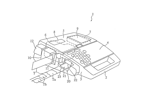
An example of a tape printer 1 is shown in Fig. 1. Tape printer 1 comprises case3 having grip 2 formed at the front thereof. Keyboard 4 is provided in the front half of
case 3, the back half of which is enclosed by cover 5, which can be opened and closed.
Tape cartridge 6, a printing mechanism (not shown in the figure), and display 7 are
exposed by opening cover 5 to expose the inside of case 3.
Typically the user inputs the letters to be printed using keyboard 4 while viewing
the text on display 7 through window 9, and presses a print key on keyboard 4 after
conl~ ing the input text to print to the tape. When the print key is pressed, the printer
meçh~ni~m feeds tape T from tape cartridge 6 and prints, and feeds the printed tape T out
from case 3.
Secondary case 10 is disposed at the side of case 3, and comprises tape opening
11 through which the fed tape T passes. Cutter button 12 is provided in secondary case
10 behind tape opening 1 1. When printing is completed, the tape T being fed through tape
opening 11 stops. If cutter button 12 is then pressed, the tape cutter is operated via a link
(neither being shown in the figures), and the end of tape T is cut square near tape opening
11.
Also disposed in secondary case 10 in front of tape opening 11 are tape insertion
path 21 of tape end ~ ing appaldlus 20 forming the essential component of the present
invention, and tape insertion opening 22 adjoining tape insertion path 21. Tape Ta in Fig.
1 indicates the maximum tape width that can inserted to tape insertion opening 22. When
the end of m~xhllulll-width tape Ta is inserted to tape insertion opening 22, both corners
of the leading edge of tape Ta are cut to the defined shape, such as a curved shape. Tape
Tb in Fig. 1 indicates a tape having a width narrower than the maximum width Ta that
can also be inserted to tape insertion opening 22. When the end of tape Tb is inserted to
tape insertion opening 22, only one corner is cut to shape each time the tape Tb is
inserted.
The tape T used in this embodiment is an adhesive film tape with a backing paper.
The tape printer prints only to the front of the adhesive film tape. This tape is applied to
216~2~
the desired object after cutting all four corners of the tape to shape and removing the
backing paper. Tape T may also be available in various widths, e.g., 24 mm, 18 mm, 12
mm, and 9 mm, in which case plural tape cartridges 6 holding blank tapes of the same
widths (24 mm, 18 mm, 12 mm, and 9 mm) are also available. In other words, a separate
tape cartridge 6 is provided for each usable tape width, and to print a tape of a specific
width the user must install a tape cartridge co~ ing that width of tape.
First Embodiment
Tape end trimming appaldlus 20 is described in detail below with reference to Fig.
2. As shown in Fig. 2, tape end llh~ g a~dlus 20 comprises guide means 23 forming
tape insertion path 21 and tape insertion opening 22, cutting blade 24 provided at the end
of guide means 23; and drive appaldlus 25 for ol)~ldlhlg cutting blade 24. Detection means
26 for detecting insertion of tape T to tape insertion path 21 is provided in guide means
23, and is connected to control means 27 of drive apparatus 25. In this case, guide means
23 is disposed on the outside of the tape end trimming al~paLa~us (Fig. 1), and the other
components are built in to case 3.
Guide means 23 is disposed to fit from the side of case 3 into secondary case 10projecting at the side of case 3 (Fig. 1), and comprises on the top thereof a shallow
channel-like tape insertion path 21, which is formed by passage surface 31 and a pair of
side walls 32. The pair of side walls 32 rise substantially perpendicular from the flat
passage surface 31, and are formed parallel to each other with a gap therebetween set
according to the maximum width (24 mm in this example) of tape Ta. Side walls 32together form the guide members guiding the sides of the inserted tape T, and thus form
the side position regulating means controlling the positions of the sides of the tape T for
cutting. Note that in this example the gap between the sides of tape insertion path 21 is
24.1 mm to accommodate a maximum tape Ta width of 24 mm.
By inserting the maximum width tape Ta with both sides guided by the pair of side
walls 32 (i.e., simply inserting the tape to tape insertion path 21), both corners at the
leading edge of tape Ta are cut to the desired shape. When a tape of narrower width Tb
(18 mm, 12 mm, or 9 mm in this case) is inserted with one side thereof guided by one
of the side walls 32, only the one leading corner of tape Tb is cut to shape; the other
14
216~2~3
leading corner is then cut by inserting the tape Tb with the side of the uncut corner guided
by the other side wall 32. It is to be noted that it is also possible to simply insert tape Tb
to tape insertion path 21, then slide it horizontally to the one side wall 32 to cut the one
corner, and then slide it horizontally to the other side wall 32 to cut the other corner. It
is also possible to insert tape Tb with one side thereof guided by one side wall 32, cut the
corner, and then slide the tape Tb to the other side wall 32 to cut the other corner.
A pair of supports 34 is also provided in a vertical orientation on opposing sides
of tape insertion path 21 at end 33 of guide means 23 at the side of case 3. Fixed blade
41 of cutting blade 24, described below, is fastened using a pair of set screws 35 to this
pair of supports 34. In this position, blade 51 of fixed blade 41, described below, covers
the end of tape insertion path 21 from above. More specifically, end 33 of guide means
23 forming the end of tape insertion path 21 is set back slightly from blade 51 of fixed
blade 41, and projects conforming to the shape of the edge of blade 51. A crescent-shaped
stopper 36, or end position regulating means, projects upward at the top of this shaped end
33 of guide means 23. Positioning pin 37 projects at the top of stopper 36. Blade 51 of
fixed blade 41 is fit to this positioning pin 37, and fixed blade 41 is thus positioned to
tape insertion path 21.
In this case, positioning pin 37 is positioned on the center line of tape insertion
path 21, and stopper surface 36a of stopper 36 extends symmetrically to said center line
perpendicular to tape insertion path 21. As a result, when a narrow tape Tb is inserted, the
end of tape Tb will contact stopper 36, and the insertion position of the end of this tape
Tb will be reliably controlled. The tape T inserted to tape insertion path 21 is thus
positioned by stopper 36 and side walls 32.
In addition, as shown in Fig. 3, passage surface 31 of tape insertion path 21 rises
slightly near stopper 36. As described above, blade 51 of fixed blade 41 is disposed in
opposition to passage surface 31. In addition, the gap between passage surface 31 and
blade 51 is large at the outside and gradually narrows at the inside in the insertion
direction. In other words, there is a sufficiently large gap in the area of tape insertion
opening 22 while the gap at the inside end of tape insertion path 21 is only slightly greater
than the thickness of the tape T. This makes it easy to insert the tape T to the tape
216~2~3
insertion path 21, and d~lesses the tape T to hold it flat as the tape T is inserted to
stopper 36.
Referring back to Fig. 2, cutting blade 24 comprises fixed blade 41, moving blade
42, and stud 43 linking fixed blade 41 and moving blade 42, thus forming a scissors-like
construction for cutting the tape T by a scissors action. Moving blade 42 pivots on stud
43, crossing while contacting fixed blade 41 from the bottom up to cut tape T. Fixed
blade 41 has an L-shaped cross section comprising blade Sl forming cutting edge 52, and
blade holder 53 joined to blade S1. Fixed blade 41 is fixed to guide means 23 by blade
holder 53. In this case, fixed blade 41 is produced by, for example, ~ uhlg and then
bending a stainless steel sheet, heat treating (hardening) the blade, and then grinding or
polishing the cutting edge 52.
Continuous cutting edge 52 is formed at the leading edge of blade S 1, a positioning
hole 54 for eng~ging with positioning pin 37 is formed at the middle of the leading edge,
and a pair of oval holes SS opposed to detecting ends 102 of detection means 26 is formed
inset from said leading edge. Cutting edge 52 is formed perpendicular to both front and
back sides of blade S 1, i.e., parallel to the cutting direction (Fig. 3). More specifically, the
perpendicularly-ground leading edge of blade 51 is cutting edge 52, and the corner where
this leading edge and the back of blade S1 intersect forms edge 52a of cutting edge 52.
As shown in Fig. 4, cutting edge 52 comprises right and left curved blade members
61 at the place where the corners of tape T are cut, first guide blade member 62 joining
the two curved blade members 61, and right and left second guide blade members 63
extending to the outside from the corresponding curved blade members 61.
The plane shape that is the shape of edge 52a of curved blade members 61
comprises curved members 61a having a central angle of sixty degrees, and straight
members 61b ext~n-ling from both ends of curved members 61a tangentially to the curve.
The radius of curved members 61a in this embodiment is preferably 3 mm. The angle
between the side of the cut tape T and the corresponding straight member 61b is thus
fifteen degrees, and the angle between the end (leading edge) of tape T and the other
straight member 61b is also fifteen degrees. By thus defining the central angle of curved
members 61a as less than ninety degrees, the corners of the tape T can be cut to a visually
16
216~ 13
appealing curved shape even when the tape T is not precisely positioned to the cutting
blade. It is to be noted that for the curved members to be visually appealing, the central
angle of curved members 61a shall preferably be set between fifty degrees and seventy
degrees, inclusive.
The plane shape of first guide blade member 62 is an arc following the leading
edge of the arc-shaped stopper 36 and leading to the corresponding inside ends of curved
blade members 61. The plane shape of each second guide blade member 63 leads from
one end thereof to straight member 6 lb of curved blade member 61, and curves to a right
angle perpendicular to tape insertion path 21.
Referring back to Fig. 2, moving blade 42 simil~rly has an L-shaped cross section
comprising blade 71 forming cutting edge 72, and blade holder 73 joined to blade 71.
Moving blade 42 is fixed to stud 43 by blade holder 73 in a manner allowing moving
blade 42 to pivot freely thereon. Moving blade 42 is also produced by ~ lpillg and then
bending a stainless steel sheet, but the blade is not heat treated (hardened). As a result, the
hardness of fixed blade 41 is greater than the hardness of moving blade 42. The sound of
fixed blade 41 and moving blade 42 meshing together is therefore lower, and the cutting
sound of the blades is not irritating. In addition, moving blade 42 wears with repeated
cutting operations, but very little wear to fixed blade 41 occurs. As a result, there is very
little change in the cut shape of tape T, which is positioned to edge 52a of fixed blade 41,
and the desired curved shape can be m~int~ined. Moreover, because cutting edges 52 and
72 project into the direction of the cutting operation, there is no change in the shape of
cutting edges 52 and 72 as wear advances, and the cutting ability of cutting blade 24 does
not deteriorate. Furthermore, as fixed blade 41 and moving blade 42 wear and adapt to
each other, the m~hing sound (cutting noise) decreases. Moreover, it is sufficient to heat
treat only the area of cutting edge 52 or only the area of blade S1. In addition, when a
carbide steel or hardened stainless steel is used, moving blade 42 may also be normalized.
Cutting edge 72 of moving blade 42 is shaped complementary to cutting edge 52
of fixed blade 41, and is perpendicular to the front and back faces of blade 71, i.e., to the
direction of the cutting operation, similarly to fixed blade 41. Moving blade 42 is
supported in a freely pivoting manner on stud 43 in the middle of the length of blade
holder 73 such that the range of rotation is limited by drive apparatus 25. The axial center
21642~3
of stud 43 is positioned above blade 51 of fixed blade 41, and cutting edge 72 of moving
blade 42 slides past cutting edge 52 of fixed blade 41 at an angle to the cutting direction.
In other words, some part of cutting edge 72 of moving blade 42 is in constant contact
with some part of cutting edge 52 of fixed blade 41 throughout the range of rotation, and
the tape T is cut by moving the contact point from the stud 43 side forward.
Stud 43 comprises a resin bushing 81 and a caulked pin 82 that functions æ the
rotational axis of moving blade 42. Fixed blade 41 and moving blade 42 are disposed on
opposing sides of bushing 81, and are held together by pin 82 passing through fixed blade
41, moving blade 42, and bushing 81. Moving blade 42 is thus pressed toward fixed blade
41 in this state, or more specifically is pressed against fixed blade 41 via the bushing 81.
As a result, a gap does not develop between cutting edge 72 of moving blade 42 and
cutting edge 52 of fixed blade 41 even after moving blade 42 has worn noticeably, and
a good cutting ability is retained in cutting blade 24.
Drive a~lus 25 comprises drive motor 91, worm gear 93 fastened to output
shaft 92 of drive motor 91, worm wheel 94 meshing with worm gear 93, and operating
pin 95 projecting from worm wheel 94. Operating pin 95 engages with cut-out slot 74 in
moving blade 42. Worm gear 93 and worm wheel 94 reduce the torque and speed of drive
motor 91 while also ch~nging the direction of rotation, and cause opeldLil1g pin 95 to
rotate around the rotational axis of worm wheel 94. Operating pin 95 and cut-out slot 74
in moving blade 42 form a positive motion cam causing moving blade 42 to rock bymeans of operating pin 95 rotating while sliding along cut-out slot 74. In other words,
when drive motor 91 is driven, moving blade 42 reciprocates through a certain angle to
cut tape T. It is to be noted that the frequency of moving blade 42 reciprocation is
preferable set to approximately one second.
Driving drive motor 91 is controlled by control means 27 in accordance with a
detection signal input from detection means 26, which detects insertion of tape T to tape
insertion path 21.
Referring again to Fig. 3, detection means 26 is located in hollow 38 of guide
means 23, and comprises switch arm 101 and detection switch 103. Detecting end 102 of
switch arm 101 faces tape insertion path 21, and detection switch 103 contacts the lower
18
21642~3
end of switch arm 101. Switch arm 101 is further fastened to guide means 23 at the top
of the inside hollow 38 in a manner allowing switch arm 101 to rotate freely between a
non-detection position and a detection position. In the non-detection position detecting end
102 obstructs tape insertion path 21, and in the detection position is retracted from tape
insertion path 21.
Detection switch 103 may be, for example, a microswitch with switch lever 104
thereof in contact with the lower end of switch arm 101 and pushing switch arm 101
toward the non-detection position. Detection switch 103 is thus OFF when switch arm 101
is in the non-detection position, and becomes ON when switch arm 101 is rotated from
the non-detection position to the detection position. Detection switch 103 continuously
outputs the detection signal when in the ON state.
Detecting end 102 of switch arrn 101 splits the top end of switch arm 101 into two
parts, forming a pair of detector projections 102a and 102b each disposed in a direction
projecting into tape insertion path 21. The pair of detector projections 102a and 102b is
provided before stopper 36 in the insertion direction, and are exposed through the pair of
guide holes 39 formed in guide means 23 to oppose the leading edge of the tape T as it
is inserted to tape insertion path 21. The pair of guide holes 39 match the pair of oval
holes 55 formed in fixed blade 41, and permit the ends of detector projections 102a and
102b to enter oval holes 55 as detector projections 102a and 102b rotate to the non-
detection position.
Thus, when tape T is inserted to tape insertion path 21, the leading edge of tape
T pushes back on detector projections 102a and 102b, thus rotating switch arm 101, and
contacts stopper 36. As a result, detection switch 103 becomes ON a moment before tape
T contacts stopper 36. It is therefore possible to gradually cut the corners of tape T to the
desired curved shape. Furthermore, because detecting end 102 of detection means 26
comprises a pair of detector projections 102a and 102b, it is not necessary to provide a
large opening for detecting end 102 in guide means 23 and fixed blade 41, and the
mechanical strength of end 33 of guide means 23 and blade 51 of fixed blade 41 is not
mpaired.
19
21642~3
If, as shown in Fig. 5, Ll is the distance between the outside edges of both
detector projections 102a and 102b, L2 is the distance between the inside edge of one
detector projection 102a and the nearest side wall 32, and L3 is the distance between the
inside edge of the other detector projection 102b and the other side wall 32, the plane
positions of the pair of detector projections 102a and 102b are set such that L2 equals L3,
and Ll, L2, and L3 are each less than the width of the narrowest usable tape T (9 mm
wide in this example). When thus comprised, switch arm 101 will rotate to the detection
position and turn detection switch 103 ON irrespective of where in the widthwise direction
of tape insertion path 21 tape T is inserted, even if the tape T is of the narrowest usable
tape width. In addition, if the inserted tape T is less than the maximum width and is
moved horizontally across tape insertion path 21, switch arm 101 will remain in the
detection position, and detection switch 103 will remain in the ON state.
It is to be noted that the detection signal is in this embodiment output continuously
while detection switch 103 is ON (for a m~imllm five seconds as described below), and
moving blade 42 thus continues the reciprocating action relative to fixed blade 41. For
example, when moving blade 42 starts to rotate from a position below fixed blade 41,
moving blade 42 slides across fixed blade 41 from below and cuts the corners of tape T.
However, when moving blade 42 starts to rotate from a position above fixed blade 41,
moving blade 42 bends the corners of tape T as it passes fixed blade 41, and then cuts
tape T as it then rotates up. As a result, tape T is reliably cut irrespective of from where
moving blade 42 starts to move, i.e., irrespective of where moving blade 42 stops. This
means that it is not necessary to control the stop position of moving blade 42.
It is to be noted that a photointellulJlel may be used in place of detection switch
103. More specifically, an optical sensor can be used in place of a mechanical switch to
detect insertion of tape T to tape insertion path 21. In this case, the structure of detection
means 26 can be further simplified.
Control means 27 comprises CPU 111 and motor drive circuit 112 as shown in
Fig. 6. When the detection signal is input from detection switch 103 to CPU 111, CPU
111 controls and drives drive motor 91 through motor drive circuit 112. More specifically,
when tape T is inserted to tape insertion path 21, drive motor 91 starts, and when tape T
is removed, drive motor 91 stops.
216~2~ )
CPU 111 also comprises timer 113 for counting a preclet~rmined period, preferably
five seconds in this embodiment, from the start of drive motor 91 operation. When this
period elapses, CPU 111 overrides the detection signal from detection switch 103 and
stops drive motor 91. This prevents overhe~ting of drive motor 91 if foreign matter
becomes trapped, and prevents unnecessary power consumption.
The procedure executed by CPU 111 to control drive motor 91 is described below
with reference to the flow chart in Fig. 7. The first step (S1) is to reset CPU 111 timer
113 to zero. A determination is then made in step S2 whether tape T is inserted to tape
insertion path 21. If the tape T is not inserted, step S2 loops back and CPU 111 thus
continuously checks for tape T insertion. When tape T is inserted to tape circuit insertion
path 21, CPU 111 starts drive motor 91 by means of motor drive 112 (S3), and in step
S4 timer 113 starts counting. It is then determined whether tape T has been removed
from tape insertion path 21 in step S5. If tape T has been removed, (step S5 returns NO),
drive motor 91 in step is stopped S7. If the tape T has not been not removed (S5 = YES)
it is determined in step S6 whether five seconds have passed since tape T was inserted.
If five seconds has elapsed (S6 = YES) then NO for 91 is also stopped in step S7.
Otherwise the procedure returns to step S5.
The operation of tape end l~ g app~lus 20 according to the present
embodiment of the invention is described briefly below with reference to Fig. 5. Tape T
is depressed by finger S as it is inserted to tape insertion path 21 guided by one side wall
32. When tape T is fully inserted to tape insertion path 21, tape T is positioned by said
side wall 32 and stopper 36, and one of the leading corners is cut. After confirrning that
the tape T has been cut based on the sound of cutting, tape T is slid horizontally to the
other side wall 32. The tape T is thus positioned by said other side wall 32 and stopper
36, and the other corner is cut. Note that this is the operation used to cut both corners of
a tape Tb narrower than the greatest possible tape width Ta. When a tape of the greatest
width Ta is fully inserted to tape insertion path 21, it is positioned by both side walls 32
and stopper 36, and both corners are simultaneously cut to shape.
As described above, both corners of tape T can be cut to shape by simply inserting
tape T to tape insertion path 21 to cut one corner and then sliding it horizontally to cut
216~2 13
the other corner. It is therefore possible to efficiently cut both corners of tapes T of
various widths using a single cutting blade 24.
Though not specifically shown in the figures, it is also possible to handle tapes of
even greater widths by providing a pair of right and left cutting blades 24. In this case,
the reciprocation range of each moving blade 42 can be reduced, and the overall tape end
trimming apl~al~lus 20 can be built more compactly.
Second Embodiment
A second embodiment of a tape end trimming al~palalus according to the present
invention is described below with reference to Figs. 8 and 9. In this second embodiment,
a path width adjusting mech:~niem 121, as shown in Fig. 9, for adjusting the width of tape
insertion path 21 is built in to guide means 23, and cutting blade 122, as shown in Fig.
8, is shaped to be able to simultaneously cut both leading edge corners of tapes T of
various widths.
Path width adjusting mech~niem 121 comprises a pair of right and left adjustmenttabs 123, a m~tching pair of right and left moving blocks 124 moving in conjunction with
adjustment tabs 123, and an internal linkage mechanism (not shown in the figures)
connecting the two moving blocks 124 to each other. Each adjustment tab 123 projects
above the top of guide means 23, and is disposed in guide means 23 in a manner
permitting both adjustment tabs 123 to slide freely therein. The base ends of adjustment
tabs 123 are fastened to the corresponding moving blocks 124, and the exposed ends of
moving blocks 124 move into and out of tape insertion path 21 through openings formed
in side walls 32 to effectively adjust the width of tape insertion path 21.
The internal linkage mechanism is, for example, an X-shaped linkage of which theends are engaged with moving blocks 124, thus linking the movement of moving blocks
124 operated by adjustment tabs 123 such that both moving blocks 124 simultaneously
move into or retract from the insertion path. As a result, the path width adjusted by the
right and left moving blocks 124 is changed relative to the center line of tape insertion
path 21.
216~2~3
Cutting blade 122 comprises fixed blade 125, moving blade 126, and stud 127
similarly to the cutting blade of the first embodiment. Cutting edge 131, however, is
symmetrically shaped in stages corresponding to plural tapes T of different widths. In the
example shown in Fig. 8, cutting edge 131 is formed for tapes T of three possible widths,
and comprises right and left first cutting edges 131a for cutting both corners of tape T1
of the greatest possible width, right and left second cutting edges 131b for cutting both
corners of tape T2 of an intermediate width, and right and left third cutting edges 131c
for cutting both corners of tape T3 of the narrowest width. Cutting edges 131a, 131b, and
131c are formed in this example in sequential stages bulging out towards the center as
shown in Fig. 8. Of course, as will be appreciated by one of ordinary skill in the art,
while in this example three diffGlGlll widths were shown, other numbers of widths are also
contemplated.
Cutting edge 132 of moving blade 126 is shaped complementary to cutting edge
131 of fixed blade 125. Moving blade 126 and fixed blade 125 are furthermore disposed
with the center line of cutting edge 131 of fixed blade 125 and the center line of cutting
edge 132 of moving blade 126 is aligned with the center line of tape insertion path 21.
While not shown in the figures, a regulated position adjusting mechanism for
controlling the insertion position of the tape T according to the tape width is also provided
in guide means 23 facing tape insertion path 21. This regulated position adjusting
mech~ni~m positions the tape T1 of the greatest width to first cutting edge 131a of fixed
blade 125, positions tape T2 of the intermediate width to second cutting edge 13 lb, and
positions tape T3 of the n~10WG~l width to third cutting edge 131c. It is to be noted that
the regulated position adjusting me~h~ni~m preferably comprises a stopper or similar
member projecting into tape insertion path 21 and moving in conjunction with themovement of moving blocks 124.
It is therefore possible by means of the tape end trimming appal~lus in accordance
with this second embodiment to cut and shape both corners of tapes T of different widths
using a single cutting blade 122 and with a single cutting operation.
216~2 l3
Third and Fourth Embodiments
The third and fourth embodiments of the present invention are described below
with reference to Figs. 1 OA, 1 OB, 11 A and 11 B. The cutting blades and regulated position
adjusting mech~ni~m~ of these embodiments are identical to those of the second
embodiment described above, and the following description is therefore limited to the
structures of the insertion paths, which differ from that of the second embodiment.
In the third embodiment shown in Fig. lOA, the right and left side walls 32 of
guide means 23 are formed in steps desc~n~ling toward the inside of the insertion path,
thus forming at the top step a pair of side walls 32a forming a first tape insertion path 141
for a tape T1 of the greatest width, forming at the middle step a pair of side walls 32b
forming a second tape insertion path 142 for a tape T2 of intermediate width, and forming
at the bottom step a pair of side walls 32c forming a third tape insertion path 143 for a
tape T3 of the n~low~st width. As shown in Fig. lOB, first tape insertion path 141,
second tape insertion path 142, and third tape insertion path 143 slope towards fixed blade
125 so that the leading edge of the tape T will be applolJ,;ately directed to cutting blade
122 by the co~lc;s~ ding tape insertion path 141, 142, or 143.
In the fourth embodiment shown in Fig. 1 lA, a first tape insertion path 151 forthe narrowest tape T3 is formed as the top slot in the face of guide means 23, second tape
insertion path 152 for tape T2 of an intermediate width is forrned as the middle slot, and
third tape insertion path 153 for tape T3 of the greatest width is formed as the bottom slot
in guide means 23. Referring now to Fig. 1 lB, the first, second, and third tape insertion
paths 151 and 152 curve as they extend toward fixed blade 125.
With the ~ird and fourth embodiments of the tape end ~.;lllllli~ apparatus
according to the present invention thus described, it is possible to cut and shape both
corners of tapes T of different widths using a single cutting blade 122 and with a single
cutting operation without it being necessary to adjust the insertion path width. Fifth Embodiment
The fifth embodiment of the invention is described next with reference to Fig. 12.
In this embodiment, cutting blade 161 comprises a pair of right and left presser blades
162, and cutter bar 163 against which presser blades 162 press. Each presser blade 162
has a curved cutting edge similar to curved blade members 61 of the first embodiment,
and is fastened to the bottom of block-shaped cutter holder 164. Cutter holder 164 is
24
21642 13
pushed upward by a spring or other means, and is supported by a guide member allowing
cutter holder 164 to move vertically (note that neither spring nor guide member is shown).
Plate cam 165 contacts the top of cutter holder 164, and cam shaft 166 of plate cam 165
is connected to a motor (not shown in the figure). When the motor drives plate cam 165,
drive cutter holder 164 moves down against the force of the spring. When cutter holder
164 moves down, presser blade 162 presses against and cuts the corners of tape Tpositioned on cutter bar 163, thus shaping the corners.
Cutter bar 163 is also provided as an extension of tape insertion path 21, and thus
also functions as part of tape insertion path 21. Cutter bar 163 also comprises right and
left side walls 167 and end stopper wall 168, which position tape Ta of the greatest usable
width and enable both corners thereof to be cut at the same time. A tape Tb (not shown
in the figure) nallow~l than tape Ta is positioned by one side wall 167 and stopper wall
168 to cut one corner, and is then positioned by the other side wall 167 and stopper wall
168 to cut the other corner. It is to be noted that a rubber pad or similar member may also
be provided on the top of cutter bar 163.
While the cutting resistance of the cutting means of this fifth embodiment is
greater than that of the first embodiment above, the structure of cutting blade 161 is also
simpler. Furthermore, if the position of cam shaft 166 of plate cam 165 can be adjusted
up and down, it is also possible to cut only the adhesive-backed film part of a tape T
backed by a backing paper, thereby both shaping the tape T as desired and facilitating
removal of the backing paper.
While the invention has been described in conjunction with several specific
embodiments, it is evident to those skilled in the art that many further alternatives,
modifications and variations will be a~a~ in light of the foregoing description. Thus,
the invention described herein is intended to embrace all such alternatives, modifications,
applications and variations as may fall within the spirit and scope of the appended claims.
tape printer
tape end l~ l.l;llg a~palalus
tape insertion path
guide means
cutting blade
216~2~3
-
drive al)p~lus
detection means
control means
passage surface
side walls
stopper
fixed blade
moving blade
stud
blade
cutting edge
edge
curved members
straight members
blade
drive motor
switch arm
detecting end
detector projections
detection switch
CPU
timer
path width adjusting mechanism
cutting blade
first tape insertion path
second tape insertion path
third tape insertion path
cutting blade
presser blade
cutter bar
tape
26