Note: Descriptions are shown in the official language in which they were submitted.
~ W095/0~76 21 6 ~ 7 9 7 PCT~S94/07737
SOFT TISSUE AUGMENTATION APPARATUS
Field of the Invention
This invention relates generally to soft tissue
augmentation, and more particularly to corrections of soft
tissue defects by the insertion of biocompatible flexible
implants having a cavity into which fibrous tissue can grow
and thus which predictably and stably augment tissue
defects.
Backqround of the Invention
Soft tissue augmentation can be temporary or
permanent. Temporary corrections can be achieved by
lifting (e.g. face lifting), fat or collagen injections.
Permanent corrections have been suggested through the use
of homogenic and alloplastic implants. Homogeneous
implants can have absorption problems and further incur
disease transmission problems.
The properties of various synthetic implant
materials have been reported when used in facial
augmentation procedures, particularly for reconstructions.
Synthetic implants have been used in augmentation
procedures. The materials used include solid, medical-
grade silicone rubber ("Silastic," available from Dow-
Corning Corp., Midland, Michigan), braided, multifilament
PET ("Mersilene," available from Ethicon Corp.,
Summerville, New Jersey), polyamide mesh ("Supramid,~
available from S. Jackson, Inc., Alexandria, Virginia),
polytetrafluoroethylene resin ("Teflon," available from
C.R. Baird, Inc., Billerica, Massachusetts),
polytetrafluoroethylene carbon ("Proplast," available from
Vitek, Inc., Houston, Texas), hydroxyapatite (available
from Integrated Orbital Implants, San Diego, California),
and expanded, fibrillated polytetrafluoroethylene, or PTFE
("Gore-Tex," available from W.L. Gore, Phoenix, Arizona).
--1--
W095/0~76 2 ~ 6 ~ 7 ~ 7 PCT~S94/07737 -
Thus, Stucker reports firming rolling polyamide
mesh and placing the implants in incised locations to
correct nasal dorsal deformities, for chin augmentation, or
for underdeveloped maxilla associated with cleft lip nose.
Stucker, "Use of Implantation in Facial Deformities,"
Laryngoscope, 87, pp. 1523-1527 (1977). Later, Stucker and
coauthors reported further facial contouring procedures,
again using polyamide mesh, which was folded into layers
and then tightly rolled. These implants were used to
augment the nasal dorsum through incisions to prepare the
recipient site. Stucker et al., "Technical Aspects of
Facial Contouring Using Polyamide Mesh," Otolaryngol. Clin.
North Am., 1~:1, pp. 123-131 (1982).
However, polyamide when implanted gives rise to
some tissue reaction and undergoes some hydrolytic
degradation that results in a gradual loss of tensile
strength. Thus, Beekhuis describes use of Mersilene mesh
as an alternative dorsal nasal filler in saddle nose
deformities, for chin implants, and the like reconstructive
surgical procedures. Beekhuis, "Mersilene Mesh to Augment
the Nasal Bridge," Am. J. Cosmetic Surg., 3:2 (1986).
Maas et al. compared the gross behavior of various
currently used implant materials for facial bone
augmentation at different sites in dogs. The authors
concluded that the site of implantation and implant
movement were important factors in determining the nature
of the tissue response and the fate of implants. Maas et
al., "Comparison of Biomaterials for Facial Bone
Augmentation," Arch. Otolaryngol. Head Neck Surg., 116, pp.
551-556 (1990).
Several authors have recently discussed the use
of Gore-Tex implants. Thus, Rothstein et al. have used
patches of the PTFE material for saddle nose deformities in
nasal augmentation operations. Rothstein et al., "The Use
of Gore-Tex Implants in Nasal Augmentation Operations," EN
Technology, pp. 40-45, (1989). Similarly, Waldman reports
use of Gore-Tex soft tissue patches as dorsal implants
-2-
-
~,TI~S94/07737
2166797 ~ JUN'95
where the patch (or layers of patches) was placed over
incisions and intranasal and extranasal incisions
closed. Waldman, "Gore-Tex for Augmentation of the
Nasal Dorsum: A Prel ;min~y Report," Anal. Plas. Surg.,
26:6 (1991). Mole has used patches or strips of the
- material inserted by a needle-like instrument with the
implant kept in place using a transfixing cutaneous
needle. Mole, "The Use of Gore-Tex Implants in
Aesthetic Surgery of the Face," Plas. Reconst. Surg.,
90:2, pp. 200-206 (1992).
However, the strips, patches, sandwiches, and
tightly rolled ~ forms of implants previously and
presently used have had various drawbacks and dis-
advantages, such as the necessity for relatively large
incisions to achieve implantation and the limited amount
of tissue ingrowth.
Summary of the Invention
In one aspect of the present invention, a soft
tissue augmentation kit comprises a flexi~le implant and
an insertion tool for the implant. The implant defines
an interior cavity which can serve several functions.
The cavity can permit the implant to be mounted or
carried by the insertion tool, preferably so that the
implant can be inserted and positioned subcutaneously
into soft tissue through a very small incision. The
cavity can also serve for anchoring the implant by
fibrous tissue ingrowth.
The implant is formed of a biocompatible
material, and preferably has a cross-section be~ween
exterior and interior surfaces that is permeable to red
blood cells. Preferred permeability is where the cross
section has pores of between about 10 to about 50 ~.
Additional objects, advantages, and novel
features of the invention will be set forth in the
description which follows and will also become apparent
to those skilled in the art.
f ~
D ~EET
W095/02376 b~ 7 9 ~ PCT~S94/07737
Brief Descri~tion of the Drawinqs
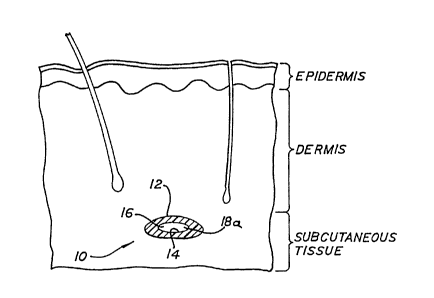
Figure 1 i8 a cross-section, broken away,
illustrating soft tissue from the outermost layer of the
epidermis into the subcutaneous layer with an implanted
embodiment of the invention in place;
Figure 2 is a side view of one kit embodiment of
the invention; and
Figure 3 is an exploded side view, partially
broken away, of a second kit embodiment.
Detailed Description of the Preferred Embodiments
Implants of the invention are flexible. When this
flexibility is combined with an interior cavity, the
implant after insertion in soft tissue will tend to assume
a sloping, smoothly tapered shape. For example, with
reference to Fig. 1, an implant 10 embodiment is
illustrated having an exterior surface 12, and interior
surface 14, and a cavity 16. The Fig. 1 illustration shows
implant 10 with a generally oval cavity 16, the oval shape
of which results after a generally longitudinally extending
body of flexible, porous material with a bore therethrough
is implanted into soft tissue, such as where implant 10 is
inserted subcutaneously under a glabellar facial wrinkle or
a nasal labial fold.
In the Fig. 1 illustration of the implant 10
embodiment, cavity 16 has at least one opening 18a adjacent
to the exterior surface 12 through which fibrous tissue
grows into the cavity. As will be further described
hereinafter, cavity 16 also serves as a means by which
implant 10 can be carried on or by an insertion tool and
then left in the desired position when the insertion tool
is removed.
In the one preferred embodiment, implant 10
longitudinally extends and the cavity 16 is a bore therein
and therethrough that opens at both ends to the exterior.
Thus, cavity or bore 16 is in fluid communication with the
surrounding soft tissue when inserted, and substantial
--4--
W095/02376 ~ 6 ~ ~ ~ 7 PCT~S94/07737
tissue ingrowth will occur a suitable period of time after
insertion. At least a portion of the implant between the
exterior surface and the cavity, (transverse to the
longitudinal axis a spaced distance from one end),
preferably a cross-section between exterior surface 12 and
lnterior surface 14, is permeable to red blood cells. This
red blood cell permeability further encourages tissue
ingrowth from exterior surface 12 towards cavity 16 after
insertion and also assists in promoting flow of fluids into
cavity 16 for tissue ingrowth and resultant implant 10
anchoring.
Implant 10 is formed of a biocompatible material
that can be either non-biodegradable (for permanent
implants) or biodegradable (for temporary implants).
Biodegradable materials may be preferred for forming
implants of this invention in instances such as lip
augmentation, where a temporary effect may be desired.
Suitable biodegradable materials include woven
polymers such as the glycolide/lactide copolymers available
from Ethicon ("Vicryl") and polyglycolides available from
American Cyanamid ("Dexon"). Such materials, in yarn form,
have been used as semi-absorbable or absorbable suture
materials.
However, implant embodiments of the invention will
more typically be formed from non-biodegradable materials
so as to be used as relatively permanent implants for
augmenting soft tissues of the face and body such as scars,
wrinkles, or depressions. Additional applications
contemplated include breast implants, particularly in the
case of post-operative cosmetic surgery follow
mastectomies. In an application such as a breast implant,
the inventive implants may desirably be combined with
another material to form a composite. For example, into at
least a portion of cavity 16 can be inserted an envelope
containing a relatively high viscosity fluid, such as
saline solution or a biodegradable, non-toxic and inert oil
(e.g., peanut oil). Further, all of part of the body of
-5-
.~ ~;J~A'~ f'~ J ~r~ S ~'
~TI~ 94 / 07 7 3 7
; 6 r;? ~ 7 ~ I~E~ JUI~ 95
the implant can include, carry, or be impregnated with
a therapeutically effective drug, such as an antibiotic
to prevent -infection or fibroblast growth ~actors.
As will be understood, for the various desired
applications by which implants of the invention will be
~ used, the shape and ~imP~ions will be varied by
cr:iteria readily ascert~;n~hle by persons skilled in the
art.
Particularly contemplated is where a plurality
of differently dimensioned implants will be sterilely
packaged with the ~;r~n~ions adapted for particular soft
tissue areas seleçted for augmentation. For example, a
sterile package (with any of various known means to open
or release and permitting opening by the surgeon or
asæisting personnel at the time of insertion) can
desirably include a pair of implants for both nasal
labial folds and one or more, typically smaller or
shorter implants for filling one or more glabellar
facial wrinkles.
The package in which the implan~ or plurality
of implants are maintained in sterile condition until
us~ can take a variety of forms known to the art. The
packaging material itself can be bacteria, 1uid and/or
vapor impermeable, such as film, sheet, or tube,
polyethylene, polypropylene, poly(vinylchloride), and
poly(ethylene terephthalate)~ with seams, joints, and
seals made by conventional techniques, such as, for
example, heat sealing and adhesive bonding. Examples of
heat sealing include sealing through use of heated
rollers, sealing through use of heated bars, rfadio
frequency sealing, and ultrasonic sealing. Peelable
seals based on pressure sensitive adhesives may also be
used.
It will be understood that the choice of
packaging material will be at least in part dependant on
the method of sterilization to which the package will be
subjected (e.g. steam autoclaving, exposure to ionizing
radiation, or exposure to oxidizing gases such peracetic
acid vapor as discussed by U.S. Patent 5,084,239, issued
Ja~uary 28, 1992, and U.S. Patent 5,115,166, issued~ May
19, 1992.
N~ S~EET
W095/02376 PCT~S94/07737
21~&'~7
The package can also include a portion that is
permeable to gas or vapor, but impermeable to bacteria.
Such a gas or vapor permeable portion will typically be
microporous with the volume average diameter of pores being
in the range of from about 0.02 to about 0.5 ~. Suitable
microporous materials include spun bonded polyethylene,
spun bonded polypropylene, microporous polyethylene, and
microporous polypropylene, usually in the form of film or
sheet. Paper can also be used as the permeable portion.
The gas or vapor permeable portion will normally be
configured so as to define at least one path for providing
entry of sterilizing gas, where post-packaging
sterilization is contemplated. For example, U.S. Patent
4,937,115, issued June 26, 1990, discloses a sterilizable
or sterilized package for packaging medical items.
Suitable biocompatible, non-biodegradable
materials include expanded, fibrillated polytetrafluoro-
ethylene ("Gore-Tex"), polyethylene terephthalate
("Mersilene"), polyamide, and the like materials, so long
as they are biocompatible and sterilizable, can be formed
into the desired shape with an interior cavity and have a
permeable fluid and red blood path between exterior and the
cavity. Sufficient permeability is whereby the implant is
permeable to red blood cells (which are of about 6-7 ~ in
diameter), preferably a permeability so that pores are in
a size range of about 10 to about 50 ~. Even larger pore
diameters are feasible, but the textural compatibility to
soft tissue will begin to be lost.
The implants can be formed into the desired shapes
and sizes (e.g. small diameter tubes for wrinkles, but
larger, more globular shapes for applications such as
breast implants) by various conventional manufacturing
techniques, such as, for example, extrusion.
The expanded, fibrillated PTFE material is
particularly preferred due to studies demonstrating
acceptable biocompatibility in a long-term animal model.
This material has an average pore size of 22 ~; however, it
--7--
W095/02376 ~ PCT~S94/07731
does not appear to allow sufficient fibrous tissue ingrowth
for good anchoring. This is illustrated by Comparative
Example l.
COMPARATIVE EXAMPLE 1
The experimental (non-inventive) implants
consisted of patches of fibrillated, expanded PTFE with
thicknesses of 2 mm. There were no orifices in the
implants, and the patches were prepared from packaged sheet
materials sold by W.L. Gore.
Nine pathogen-free male and female New Zealand
white rabbits weighing 2-4 kg were used in the study.
Care, handling, and surgical procedures were performed in
accordance with the guidelines and standards set by the
Institutional Review Board's Committee on Animal and Human
Research. The animals were anesthetized with intravenous
ketamine (40 mg/kg) and xylazine (7 mg/kg).
After the animals were shaved and prepared, the
nasal dorsum was draped and a l.0 cm anterior incision was
made through the skin and subcutaneous tissues. A limited
subcutaneous pocket was formed using the scissors technique
over the nasal dorsum. T,~ml n~ted l x 2 cm implants were
cut and preoperatively sterilized according to instructions
on the package insert. The implants were then placed
directly over bone with the periosteum elevated, and the
wound was closed with interrupted 4-0 nylon sutures. The
animals were carefully observed on a daily basis for signs
of wound infection, seroma, or hematoma formation. Sutures
were removed one week postoperatively. The animals were
euthanized prior to necropsy by injection of intravenous
Phenobarbital. At the time of necropsy, all implants were
carefully palpated and graded for stability using manual
manipulation.
The animals were equally divided into early (3
weeks), intermediate (6 months), and long-term (12 months)
implant groups. Tissue specimens including skin, implant,
and underlying bone were removed en bloc. A portion of the
--8--
W095/02376 %1 6 6 ~ 9 ~ PCT~S94/07737
bloc was used as a fresh tissue specimen for fixation and
preparation for scanning electron microscopy.
All implants remained freely mobile by palpation
after a 3 week period of implantation. None of the
implants were lost or extruded and there was no evidence of
wound infection, hematoma, or seroma formation. In the
intermediate group (6 months), two of the six remaining
test ~nl m~l implants demonstrated stability within soft
. tissue, with four implants freely mobile within the soft
tissues. The long-term (12 months) test animal implants
demonstrated stability within soft tissue.
Within the substance of the material, no tissue
ingrowth was observed in the early group. Little or no
fibrosis was seen in this group, neither within the
material substance nor at its periphery. Routine light
microscopy did not show material substance loss,
degradation, or breakdown in the early study group. When
studied under sc~nn;ng electron microscopy, the early group
specimens demonstrated a delicate, fibrinous network of
tissue directly adherent to the material substance. In
addition, a small number of acute and chronic inflammatory
cells were seen in association with the material. No
evidence of breakdown or degradation of a material
substance was observed.
The intermediate study group (6 months)
demonstrated absence of acute inflammatory cells at the
tissue-implant interface. Scattered and moderate numbers
of chronic inflammatory cells were seen focally, with an
occasional, rare, foreign body giant cell present. The
central portions of the material, however, demonstrated no
ingrowth of host tissue or cells. No significant
thickening occurred and minimal fibrous tissue ingrowth was
seen at the periphery of the material. No evidence of
destruction, loss of integrity, or resorption of the
material was observed in this group. Scanning electron
microscopy of the intermediate (6 month) implant group
demonstrated an increase in the delicate but adherent
_ g _
21~6797
W095/0~76 PCT~S94/07737
fibrous tissue network over the implant surface. A few
chronic and acute inflammatory cells were present; however,
changes in the material's structural integrity were not
apparent. The delicate fibrous pseudocapsule described on
routine microscopy was closely adherent to the material.
The long-term (12 month) implant group
demonstrated very little change in tissue response or
material substance from the intermediate group. A delicate
fibrous tissue capsule was consistently present in the
three r~ n;ng animals, but showed no evidence of
thickening. Occasional chronic inflammatory cells and a
moderate number of fibroblasts were observed growing into
the periphery of the implant and only scant and focal
foreign body giant cells were present. No evidence of
underlying bone changes or changes to the material~s
integrity was observed. Scanning electron microscopic
studies of the long-term implant group also showed very
little change in tissue character from the intermediate
group. A small increase in the organization of the thin
fibrous capsule and a slight thickening of the delicate
stromal components of the adherent fibrous tissue was
present. There were, however, vocal areas that suggested
some loss of the surface integrity of the material. These
areas were scattered and focal without consistency in their
relationship to the underlying bone or soft tissue. No
chronic inflammatory cell reaction or evidence of material
phagocytosis was present in the area surrounding these
focal irregularities. These areas may represent simple
mechanical damage to the implant material during handling.
Thus, although the PTFE material is porous, it
does not allow much fibrous tissue ingrowth, and the small
amount of fibrous tissue ingrowth that does occur is only
sufficient to confer some limited stability of an implant
ln the form of a solid structure in soft tissues over time.
This conclusion appears to contradict information said to
originate with W.L. Gore (see Rothstein et al., supra,
-10-
W095/0~76 ~l ~ 6 7 ~ 7 PCT~S94/07737
footnote 9). However, the Gore-Tex material itself appears
to be a safe and reliable substance. We believe one
advantage provided by the inventive implants 10 requiring
the presence of a cavity 16 with at least one end 18a open
to the exterior is the property of substantial tissue
ingrowth leading to secure anchoring of the inventive
implants. Thus, inventive implants 10 avoid or reduce the
palpable rigidity or movement that is inherent in cord or
sheet forms.
Although one aspect of this invention is a soft
tissue augmentation device that can consist essentially
only of the inventive implant or plurality of implants, a
soft tissue kit is contemplated that includes an insertion
tool for the implant. The insertion tools will be of a
construction either to be sterilizable or more preferably,
all or part of the insertion tools will be disposable. Two
insertion tool embodiments will now be described.
Turning to Fig. 2, implant 10 is shown mounted on
or carried by an insertion tool 20 in its pre-insertion
configuration. The insertion tool 20 comprises a
relatively flexible, non-compressible, longitudinally
extending shaft 22 with a distal end 26 and a proximal end
27. Shaft 22 preferably mates with, or conforms to,
orifice 16 of implant 10.
Distal end 26 is comprised of a tapered tip 28
sharp enough to pierce the surface of the dermal layer
under which the implant 10 is to be subcutaneously placed.
Proximal end 27 is comprised of a handle 24 (either
separately formed and attached to shaft 22 or formed as a
unitary body with shaft 22).
In an example of operation, the physician
manipulates handle 24 to push tip 28 through the dermis at
the proximal end of the area where implant 10 is to be
placed, thereby creating a subcutaneous canal.
The instrument is designed for the surgeon to push
the sharp point through the intact skin. However, an
WO9~/0~76 PCT/US94/07737
incision can be made initially if the surgeon so desires or
when the size of the implant dictates.
In the embodiment of Fig. 2, it is preferred that
the tip 28 is allowed to exit the dermis at the opposite
end of the implant area to adjust and stabilize the
implant, though the dermis need not be exited if the
surgeon so desires. Flexible shaft 24 follows tip 28 into
the dermis, thereby positioning implant 10 at the desired
location within the subcutaneous canal. While stabilizing
the implant distally the shaft can be removed with a gentle
twisting motion.
The length of shaft 22 up to and including distal
end 26 is then removed from the canal through the proximal
end of the incision originally made thereby leaving implant
10 in the location and position desired.
The first embodiment insertion tool 20 can be made
in whole or part of materials such as stainless steel,
rigid plastic, or carbon fibers. This first embodiment is
preferably disposable.
A second insertion tool embodiment is shown in
Fig. 3. Implant 10 is shown carried by insertion tool 30
in its pre-insertion configuration. The insertion tool 30
comprises outer cannula 34 and a relatively flexible, non-
compressible, longitudinally extending central shaft 32
with distal end 36 and proximal end 37.
Distal end 36 is comprised of a conical or
otherwise tapered tip 38 sharp enough to pierce the surface
of the dermal layer under which the implant 10 is to be
subcutaneously placed. On the surface of tip 38 is flat
surface 40, knurled or otherwise textured to facilitate
grasping tip 38.
Central shaft 32 is joined with tip 38 (either
separately formed and attached to shaft 32 or formed as a
unitary body with shaft 32). Implant 10 is mounted on or
carried by central shaft 32. Outer cannula 34 is
positioned over both central shaft 32 and implant 10 with
its distal end adjacent to tip 38 and the opposite end
-12-
W095/0~76 2 ~ ~ ~ rl ~ ~ PCT~S94/07737
protruding proximally beyond proximal end 36 of shaft 32.
Outer cannula 34 serves to temporarily isolate implant 10
from the subcutaneous tissue and to dilate the subcutaneous
canal initially created by tip 38.
Handle apparatus 44, well known to those of
ordinary skill in the art, is adapted for use with the
invention described herein but is not illustrated in
detail. Tightening mechanism 46 enables handle 44 to grasp
outer cannula 34 and thereby manipulate insertion tool 30.
In an example of operation, the physician
manipulates handle 44, connected to the proximal end of
outer cannula 34, thus pushing tip 38 through the dermis at
the proximal end of the intended insertion area. The
remainder of insertion tool 30 follows the path of tip 38
through the subcutaneous tissue until tip 38 protrudes
through the distal end of the intended insertion area.
Again, the instrument is designed for the surgeon to push
the sharp point through the intact skin. However, an
incision can be made initially if the surgeon so desires or
when the size of the implant dictates.
Once insertion tool 30 and implant 10 are in the
desired location, the physician pulls handle 44 to remove
outer cannula 34 through the proximal end of the
subcutaneous canal, thus exposing the subcutaneous tissue
to implant 10. The physician then removes central shaft 32
from the subcutaneous canal by grasping tip 38 at textured
surface 40, using a common forceps or other similar device,
and pulling tip 38 and shaft 32 through the distal end of
the canal, leaving implant 10 in the location and position
desired, with the implant stabilized between the surgeon's
thumb and index finger the tip and shaft are removed.
The second embodiment tool 30 can be made from
materials such as stainless steel, rigid plastic, and/or
carbon fibers. The handle 44 can be sterilizable while the
r~m~in;ng portion tcentral shaft 32, outer cannula 34, and
tip 38) can be disposable and thus obviate the necessity
for sterilization.
- 13 -
W095/02376 PCT/US94107737 -
2~ t~
It is to be understood that while the invention
has been described above in conjunction with preferred
specific embodiments, the description and examples are
intended to illustrate and not limit the scope of the
invention, which is defined by the scope of the appended
claims.