Note: Descriptions are shown in the official language in which they were submitted.
WO 95105793 PCT/US94I08855
216207
1
ABSORBENT ARTICLE HAVING
COMPOSITE ELASTICIZED MEMBER
FIELD OF THE INVENTION
The present invention relates to absorbent articles such as
diapers, incontinent briefs, diaper holders, and the like, and more
particularly, to absorbent articles having a composite elasticized
member. The composite elasticized member is preferably used as a
portion of the elasticized side panel and/or the elasticized waistband
of the absorbent article.
BACKGROUND OF THE INVENTION
Infants and other incontinent individuals wear absorbent~articl,es
1 0 such as diapers to receive and contain urine and other body exudates.
Absorbent articles function to both contain the discharged materials
and to isolate these materials from the body of the wearer and from
the wearer's garments and bed clothing. Disposable absorbent articles
having many different basic designs are known to the art. For
example, U.S. Pat. No. Re. 26,152 issued to Duncan and Baker on
January 31, 1967, describes a disposable diaper which has achieved
wide acceptance and commercial success. U.S. Pat. No. 3,860,003
issued to Buell on January 14, 1975, describes an elasticized leg cuff
disposable diaper which has achieved wide acceptance and commercial
success.
However, absorbent articles have a tendency to sag or gap away
from and to slide/slip down on the body of the wearer during wear.
This sagging/gapping and sliding/slipping is caused by the relative
motions of the wearer as the wearer breaths, moves and changes
positions, by the downward forces generated when the absorbent article
is loaded with body exudates, and by the deformation of the materials
of the absorbent article itself when subjected to such wearer's
motions. This sagging/gapping and sliding/slipping of the absorbent
article can lead to premature leakage and poor fit of the absorbent
m i
WO 95!05793 PCTIUS94/08855
2
article about the wearer in the waste region and the leg regions of
the absorbent article.
In order to provide a more comfortable and contouring fit certain
commercially available absorbent articles have been provided with
elastic waist features and elasticized side panels. An example of a
disposable diaper with an elastic waist feature which has achieved
wide acceptance and commercial success is disclosed in U.S. Pat. No.
4,515,595 issued Kievit et al. on May 7, 1985. An example of a
disposable diaper with elasticized side panels positioned in the ears
1 0 (ear flaps) of the diaper is disclosed in U.S. Pat. No. 4,857,067
issued to Wood, et al. on August 15, 1989. In order for the elastic
waist feature and the elasticized side panel to perform appropriately
they must have certain characteristics. It is important for the
elastic waist feature and the elasticized side panels to be of
1 5 sufficient bulk to provide a cushioning effect which has an increased
comfort and improved fit for the wearer. In addition, it is
preferable that they be of sufficient stiffness and resilience such
that the waist and ear portions of the diaper maintain their shape
during application and use of the diaper. That is, the waist and ear
20 portions of the diaper should stand on their own and should not flop
over due to the weight of the material forming the waist feature and
side panel member. In addition, they must also have a certain degree
of elasticity in order that they may move and stretch so that they
conform with the body of the wearer during use.
25 SUMMARY OF THE INVENTION
The present invention provides absorbent articles such as
disposable diapers, incontinent briefs, diaper holders and the like,
that have a unique composite member. Such absorbent articles comprise
a containment assembly preferably comprising a liquid pervious
30 topsheet, a liquid impervious backsheet joined with the topsheet, and
an absorbent core positioned between the topsheet and the backsheet.
The absorbent core has side edges and waist edges. A composite
elastic member extends laterally outward from at least one of the side
edges of the absorbent core to form a portion of the elasticized side
35 panel. The composite member includes an elastomeric member having a
first surface and a second surface and a three-dimensional,
»
. _
r 2~ se20~
3
macroscopically expanded, formed-film secured to the first surface of the
elastomeric member.
In accordance with one embodiment, the invention provides a
disposable absorbent article, the disposable absorbent article comprising:
(a) a containment assembly including a liquid pervious topsheet, a
liquid impervious backsheet joined with the topsheet, and an absorbent
core positioned between the topsheet and the backsheet, the absorbent
core having side edges and waist edges;
(b) an elasticized side panel extending laterally outward from at
least one of the side edges of the absorbent core; and
(c) a composite member extending laterally outward from at least
one of the side edges of the absorbent core forming a portion of the
elasticized side panel, the composite member including an elastomeric
member having a first surface and a second surface and a resilient, three-
dimensional, macroscopically expanded, formed-film member secured to
the first surface of the elastomeric member, the formed-film member
having a first surface and a second surface and exhibiting a multiplicity of
apertures formed by a multiplicity of intersecting fiber-like elements
interconnected to one another in the first surface of the formed-film
member, each of the fiber-like elements having a base portion located in
the first surface and side wall portions attached to the base portion and
extending generally in the direction of the second surface of the formed-
film member, the side wall portions of the fiber-like elements being
interconnected to one another intermediate the first and second surfaces
of the formed-film member and terminating substantially concurrently
with one another in the second surface of the formed film member, the
formed film member exhibiting a caliper significantly greater than the
thickness of material from which the formed-film member is made and
exhibiting a high degree of resiliency, such that the formed-film member
imparts a significant degree of stiffness and resilience to the composite
member.
.,
;'x~~:,,~- ~.' .
21 682 07
3a
In accordance with a further embodiment, the present invention
provides a disposable absorbent article, the disposable absorbent article
comprising:
(a) a containment assembly including a liquid pervious topsheet, a
liquid impervious backsheet joined with the topsheet, and an absorbent
core positioned between the topsheet and the backsheet, the absorbent
core having side edges and waist edges;
(b) an elasticized waistband extending longitudinally outward from
at least one of the waist edges of the absorbent core; and
(c) a composite member extending longitudinally outward from at
least one of the waist edges of the absorbent core forming a portion of the
elasticized waistband, the composite member including an elastomeric
member having a first surface and a second surface and a resilient, three-
dimensional, macroscopically expanded, formed-film member secured to
the first surface of the elastomeric member, the formed-film member
having a first surface and a second surface and exhibiting a multiplicity of
apertures formed by a multiplicity of intersecting fiber-like elements
interconnected to one another in the first surface of the formed-film
member, each of the fiber-like elements having a base portion located in
the first surface and side wall portions attached to the base portion and
extending generally in the direction of the second surface of the formed-
film member, the side wall portions of the fiber-like elements being
interconnected to one another intermediate the first and second surfaces
of the formed-film member and terminating substantially concurrently
with one another in the second surface of the formed film member, the
formed film member exhibiting a caliper significantly greater than the
thickness of material from which the formed-film member is made and
exhibiting a high degree of resiliency, such that the formed-film member
imparts a significant degree of stiffness and resilience to the composite
member.
~, r°
~16$~07
3b
In accordance with a further embodiment, the present invention
provides a composite member comprising an elastomeric member having a
first surface and a second surface, and a resilient, three-dimensional,
macroscopically expanded, formed-film member secured to the first
surface of the elastomeric member, the formed-film member having a first
surface and a second surface and exhibiting a multiplicity of apertures
formed by a multiplicity of intersecting fiber-hke elements interconnected
to one another in the first surface of the formed-film member, each of the
fiber-like elements having a base portion located in the first surface and
side wall portions attached to the base portion and extending generally in
the direction of the second surface of the formed-film member, the side
wall portions of the fiber-like elements being interconnected to one
another intermediate the first and second surfaces of the formed-film
member and terminating substantially concurrently with one another in
the second surface of the formed-film member, the formed-film member
exhibiting a caliper significantly greater than the thickness of material
from which the formed-film member is made and exhibiting a high degree
of resiliency, such that the formed-film member imparts a significant
degree of stiffness and resilience to the composite member, the composite
member further includes a three-dimensional, macroscopically expanded,
formed-film member secured to the second surface of the elastomeric
member.
In a preferred embodiment the composite member includes a three
dimensional, macroscopically expanded, formed-film secured to the second
surface of the elastomeric member. Alternatively, the composite member
includes a nonwoven web secured to the second surface of the elastomeric
member.
The elasticized side panel preferably comprises a portion of the
backsheet, a portion of the topsheet, and the composite member.
Preferably, a composite elastic member extends longitudinally
outward from at least one of the waist edges of the absorbent core to form
.-~
21 68207
3c
a portion of the elasticized waistband. The composite member includes an
elastomeric member having a first surface and a second surface and a
three-dimensional, macroscopically expanded, formed-film secured to the
first surface of the elastomeric member.
In a preferred embodiment, the composite member includes a three-
dimensional, macroscopically expanded, formed-film secured to the second
surface of the elastomeric member. Alternatively, the composite member
includes a nonwoven web secured to the second surface of the elastomeric
member.
The elasticized waistband preferably comprises a portion of the
backsheet, a portion of the topsheet, and the composite member.
The term "macroscopically expanded", as used herein refers to webs,
ribbons and films which have caused to conform to the surface of a three-
dimensional forming structure so that both surfaces thereof exhibit a
three-dimensional pattern of surface aberrations corresponding to the
macroscopic cross-section of the forming structure, the surface aberrations
comprising patterns being individually discernible to the normal naked
eye, i.e., a normal eye having 20120 vision unaided by any instrument that
changes the appearance, size or distance of an object or otherwise alters
the visual powers of the eye, when the perpendicular distance between the
viewer's eye and the plane of the web is about 12 inches. Such
macroscopically expanded webs, ribbons and films are typically caused to
conform to the surface of the forming structure by embossing, i.e., when
the forming structure exhibits a pattern comprised primarily of male
projections by debossing, i.e., when the forming structure
;"~~~~
WO 95105793 PCTIUS94108855
4
exhibits a pattern comprised of primarily of female capillary
networks, or by extrusion of a resinous melt directly onto the surface
of a forming structure of either type.
BRIEF DESCRIPTION OF THE DRAWINGS
While the specification concludes with claims particularly
pointing out and distinctly claiming the subject matter which is
regarded as forming the present invention, it is believed that the
invention will be better understood from the following description
which is taken in conjunction with the accompanying drawings in which
1 0 like designations are used to designate substantially identical
elements, and in which:
Fig. 1 is a plan view of a disposable diaper embodiment of the
present invention having portions cut-away to reveal underlying
structure, the outer surface of the diaper facing the viewer;
Fig. 2 is a fragmentary sectional view of the disposable diaper
shown in Fig. 1 taken along section line 2-2 of Fig. 1;
Fig. 3 is a fragmentary sectional view of the disposable diaper
shown in Fig. 1 taken along section line 3-3 of Fig. 1;
Fig. 4 is a segmented perspective illustration of a
three-dimensional, macroscopically expanded, formed-film; and
Fig. 5 is a fragmentary sectional view of the disposable diaper
shown in Fig. 1 taken along section line 5-5 of Fig. 1.
QETAILED DESCRIPTION OF THE INVENTION
As used herein, the term "absorbent article" refers to devices
which absorb and contain body exudates, and, more specifically, refers
to.devices which are placed against or in proximity to the body of the
wearer to absorb and contain the various exudates discharged from the
body. The term "disposable" is used herein to describe absorbent
articles which are not intended to be laundered or otherwise restored
or reused as an absorbent article (i.e., they are intended to be
discarded after a single use and, preferably, to be recycled,
composted or otherwise disposed of in an environmentally compatible
manner). A "unitary" absorbent article refers to absorbent articles
which are formed of separate parts united together to form a
coordinated entity so that they do not require separate manipulative
parts like a separate holder and liner.
PCT/US94108855
~O 95105793
A preferred embodiment of an absorbent article of the present
invention is the unitary disposable absorbent article, diaper 20,
shown in Fig. 1. As used herein, the term "diaper" refers to an
absorbent article generally worn by infants and incontinent persons
5 that is worn about the lower torso of the wearer. It should be
understood, however, that the present invention is also applicable to
other absorbent articles such as incontinent briefs, incontinent
undergarments, diaper holders and liners, feminine hygiene garments,
and the like.
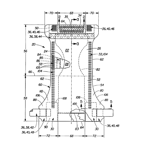
Fig. 1 is a plan view of the diaper 20 of the present invention
in its flat-out, uncontracted state (i.e., with elastic induced
contraction pulled out except in the side panel wherein the elastic is
left in its relaxed condition) with portions of the structure being
cut-away to more clearly show the construction of the diaper 20 and
with the portion of the diaper 20 which faces away from the wearer,
the outer surface 52, oriented towards the viewer. As shown in Fig.
I, the diaper 20 comprises a containment assembly 22 preferably
comprising a liquid pervious topsheet 24; a liquid impervious
backsheet 26 joined with the topsheet 24; an absorbent core 28
positioned between the topsheet 24 and the backsheet 26; elasticized
side panels 30; elasticized leg cuffs 32; an elastic waist feature 34;
and a closure system comprising a dual tension fastening system
generally multiply designated as 36. The dual tension fastening
system 36 preferably comprises a primary fastening system 38 and a
waist closure system 40. The primary fastening system 38 preferably
comprises a pair of securement members 42 and a landing member 44.
The waist closure system 40 is shown in Fig. 1 to preferably comprise
a pair of first attachment components 46 and a second attachment
component 48. The diaper 20 also preferably comprises a positioning
patch 50 located subjacent each first attachment component 46.
The diaper 20 is shown in Fig. 1 to have an outer surface 52
(facing the viewer in Fig. 1), an inner surface 54 opposed to the
outer surface 52, a first waist region 56, a second waist region 58
opposed to the first waist region 56, and a periphery 60 which is
defined by the outer edges of the diaper 20 in which the longitudinal
edges are designated 62 and the end edges are designated 64. (While
one skilled in the art will recognize that a diaper is usually
WO 95105793 PCTIUS94108855
6
described in terms of having a pair of waist regions and a crotch
region between the waist regions; in this application, for simplicity
and terminology, the diaper 20 is described as having only waist
regions, each of the waist regions including a portion of the diaper
which would typically be designated as part of the crotch region.)
The inner surface 54 of the diaper 20 comprises that portion of the
diaper 20 which is positioned adjacent to the wearer's body during use
(i.e., the inner surface 54 generally is formed by at least a portion
of the topsheet 24 and other components joined to the topsheet 24).
The outer surface 52 comprises that portion of the diaper 20 which is
positioned away from the wearer's body (i.e., the outer surface 52
generally is formed by at least a portion of the backsheet 26 and
other components joined to the backsheet 26).
The first waist region 56 and the second waist region 58 extend,
respectively, from the end edges 64 of the periphery 60 to the lateral
centerline 66 of the diaper 20. The waist regions each comprise a
central region 68 and a pair of side panels which typically comprise
the outer lateral portions of the waist regions. The side panels
positioned in the first waist region 56 are designated 70 while the
side panels and the second waist region 58 are designated 72. (In the
discussion the follows, unless otherwise noted, the diaper 20 will
comprise a pair of side panels in each waist region. While it is not
necessary that the pairs of side panels be identical, they are
preferably mirror images one of the other.) In a preferred embodiment
of the present invention, the side panels 72 positioned in the second
waist region 58 are elastically extensible in a lateral direction
(i..e., elasticized side panels 30). (The lateral direction (x
direction or width) is defined as the direction parallel to the
lateral center line 66 of the diaper 20; the longitudinal direction (y
direction or length) being defined as the direction parallel to the
longitudinal center line 61; and the axial direction (z direction or
thickness) being defined as the direction extending through the
thickness of the diaper 20.)
Fig. 1 shows a preferred embodiment of the diaper 20 in which the
topsheet 24 and the backsheet 26 have length and width dimensions
generally larger than those of the absorbent core 28. The topsheet 24
and the backsheet 26 extend beyond the edges of the absorbent core 28
PCT/US94l08855
NO 95/05793 ,
7
to thereby form the periphery 60 of the diaper 20. The periphery 60
defines the outer perimeter or, in other words, the edges of the
diaper 20. The periphery 60 comprises the longitudinal edges 62 and
the end edges 64.
Fig. 2 is a cross-sectional view of the diaper 20 taken along
section line 2-2 of Fig. 1 in the first waist region 56. Fig. 2 shows
the construction of the elasticized waistband 35 of the elastic waist
feature 34. The elasticized waistband 35 is shown in Fig.2 in its
contracted or relaxed condition. The elasticized waistband 35
preferably comprises a portion of the topsheet 24, a portion of the
backsheet 26, and a composite member comprising an elastomeric member
76 and a three-dimensional, macroscopically expanded, formed-film
member 77. The elasticized waistband 35 is also provided with regions
of securement 78 wherein the backsheet 26 and the topsheet 24 are
joined to the composite member. Since the topsheet 24 and the
backsheet 26 are gathered when the composite member is in its relaxed
condition, regions of differential securement are provided which form
pleats 80.
Fig. 3 is a fragmentary cross-sectional view of the diaper 20
taken along section line 3-3 of Fig. 1. The absorbent core 28 is
generally shown in Fig. 3 and shows the waist edge 83 of the absorbent
core 28. The topsheet 24 and the backsheet 26 encase the absorbent
core 28 and extend longitudinally outwardly beyond the waist edge 83
of the absorbent core 28 to form a waist flap 89 and the end edge 64.
The elastic waist feature 34 extends longitudinally outwardly from the
waist edge 83 of the absorbent core 28 in at least the central region
68 and forms at least a portion of the end edge 64. The elastic waist
feature 34 comprises an interconnecting panel zone 130, a first
flexural hinge zone 132 joining the interconnecting panel zone 130
with the containment assembly 22 adjacent the waist edge edge 83 of
the absorbent core 28, an elasticized waistband 35, and a second
flexural hinge zone 134. The elasticized waistband comprises a
shaping panel zone 136, a waistline panel zone 138, a predisposed,
resilient, waistband flexural hinge zone 140 joining the shaping panel
zone 136 and the waistline panel zone 138. The interconnecting panel
zone 130 comprises a portion of the topsheet 24 and the backsheet 26
i~ i
WO 95105793 PCTIUS94108855
~1
8
while the elasticized waistband comprises a portion of the topsheet 24
and the backsheet 26 and the composite member.
The containment assembly 22 of the diaper 20 is shown in Fig. 1
as comprising the main body (chassis) of the diaper 20. The
containment assembly 22 comprises at least an absorbent core 28 and
preferably an outer covering layer comprising the topsheet 24 and the
backsheet 26. When the absorbent article comprises a separate holder
and a liner, the containment assembly 22 generally comprises the
holder and the liner (i.e., the containment assembly 22 comprises one
or more layers of material to define the holder while the liner
comprises an absorbent composite such as a topsheet, a backsheet, and
an absorbent core.) For unitary absorbent articles, the containment
assembly 22 comprises the main structure of the diaper with other
features added to form the composite diaper structure. Thus, the
containment assembly 22 for the diaper 20 generally comprises the
topsheet 24, the backsheet 26, and the absorbent core 28.
The absorbent core 28 may be any absorbent means which 'is
generally compressible, conformable, non-irritating to the wearer's
skin, and capable of absorbing and retaining liquids such as urine and
other certain body exudates. As shown in Fig. 1, the absorbent core
28 has a garment surface 100, a body surface 101, side edges 82, and
waist edges 83.
The absorbent core 28 may be manufactured in a wide variety of
sizes and shapes (e. g., rectangular, hourglass, "T"-shaped,
asymmetric, etc.) and from a wide variety of liquid-absorbent
materials coamonly used in disposable diapers and other absorbent
articles such as comminuted wood pulp which is generally referred to
as airfelt. Examples of other suitable absorbent materials include
creped cellulose wadding; meltblown polymers including coform;
chemically stiffened, modified or cross-linked cellulosic fibers;
tissue including tissue wraps and tissue laminates; absorbent foams;
absorbent sponges; superabsorbent polymers; absorbent gelling
materials; or any equivalent material or combinations of materials.
The configuration and construction of the absorbent core may also be
varied (e.g., the absorbent core may have varying caliper zones, a
hydrophilic grad Tent, a superabsorbent gradient, or lower average
density and lower average basis weight acquisition zones; or may
WO 95105793 ~,. 2 ~ s $ z o ~ PCTIUS9i/08855
9
comprise one or more layers or structures). The total absorbent
capacity of the absorbent core 28 should, however, be compatible with
the design loading and the intended use of the diaper 20. Further,
the site and absorbent capacity of the absorbent core 28 may be varied
to accortmodate wearers ranging from infants through adults. Exemplary
absorbent structures for use as the absorbent core 28 are described in
U.S. Pat. No. 4,610,678 issued to Weisman et al. on September 9, 1986;
U.S. Pat. No. 4,673,402 issued to Weisman et al. on June 16, 1987;
U.S. Pat. No. 4,888,231 issued to Angstadt on December 19, 1989; and
U.S. Pat. No. 4,834,735 issued to Alemany et al. on hay 30, 1989.
The backsheet 26 is positioned adjacent the garment surface of
the absorbent core 28 and is preferably joined thereto by attachment
means (not shown) such as those well known in the art. For example,
the backsheet 26 may be secured to the absorbent core 28 by a uniform
continuous layer of adhesive, a patterned layer of adhesive, or an
array of separate lines, spirals, or spots of adhesive. Adhesives
which have been found to be satisfactory are manufactured by H. 8.
Fuller Company of St. Paul, Minnesota and marketed as HL-1258. The
attachment means will preferably comprise an open pattern network of
filaments of adhesive as is disclosed in U.S. Pat. Ho. 4,573,986
issued to Minetola et al. on March 4, 1986, more preferably several
lines of adhesive filaments swirled into a spiral pattern such as is
illustrated by the apparatus and methods shown in U.S. Pat. No.
3,911,173 issued to Sprague, Jr. on October 7, 1975; U.S. Pat. No.
4,785,996 issued to Ziecker, et al. on November 22, 1978; and U.S.
Pat. Ho. 4,842,666 issued to Werenicz on June 27, 1989.
Alternatively, the
attachment oeans may comprise heat bonds, pressure bonds, ultrasonic
bonds, dynamic mechanical bonds, or any other suitable attachment
means or combinations of these attachment means is are known in the
art.
The backsheet 26 is impervious to liquids (e.g., urine) and is
preferably manufactured from a thin plastic film, although other
flexible liquid impervious materials may also be used. As used
herein, the term 'flexible' refers to materials which are compliant
-- and wia-1 readily conform to the general shape and contours of the
i~ i i
WO 95/05793 PCTIUS94I08855
human body. The backsheet 26 prevents the exudates absorbed and
contained in the absorbent core 28 from wetting articles which contact
the diaper 20 such as bedsheets and undergarments. The backsheet 26
may thus compri se a woven or nonwoven materi al , polymeric fi lms such
5 as thermoplastic films of polyethylene or polypropylene, or composite
materials such as a film-coated nonwoven material. Preferably, the
backsheet is a thermoplastic film having a thickness of from about
0.012 mm (0.5 mil) to about 0.051 mm (2.0 mils).
In a preferred embodiment of the present invention, at least a
10 portion of the backsheet 26 is subjected to mechanical stretching in
order to provide both a "zero strain stretch laminate that forms the
elasticized side panels 30 and to prestrain the portion of the
backsheet coinciding with the elastic waist feature. Thus, the
backsheet 26 is preferably elongatable, most preferably drawable, but
not necessarily elastomeric, so that the backsheet 26 will, upon
mechanical stretching, be at least to a degree permanently elongated
such that it will not fully return to its original undistorted
configuration. In preferred embodiments, the backsheet can be
subjected to mechanical stretching without undue rupturing or tearing.
Thus, it is preferred that the backsheet 26 have an ultimate
elongation to break of at least about 400x to about 700% in the
cross-machine direction as measured using a method consistent with the
ASTM (American Society of Testing Materials) D-638. Thus, preferred
polymeric films for use as the backsheet contain a high content of
linear low density polyethylene. Particularly preferred materials for
the backsheet 26 include blends comprised of about 45-90x linear low
density polyethylene and about 10-55% polypropylene. Exemplary films
for use as the backsheet include RR8220 blend for blown films and
RR5475 blend for cast films as manufactured by Tredegar Industries,
Inc. of Terre Haute, Ind. The backsheet 26 is preferably embossed
and/or matte finished to provide a more clothlike appearance.
Further, the backsheet 26 may permit vapors to escape from the
absorbent core 28 (i.e., breathable) while still preventing exudates
from passing through the backsheet 26.
The topsheet 24 is positioned adjacent the body surface of the
absorbent core 28 and is preferably joined thereto and to the
backsheet 26 by attachment means (not shown) such as those well known
YO 95105793 ~ ~ ~ ~ n,PCTlUS94108855
11
in the art. Suitable attachment means are described with respect to
joining the backsheet 26 to the absorbent core 28. As used herein,
the term "joined" encompasses configurations whereby an element is
directly secured to the other element by affixing the element directly
to the other element, and configurations whereby the element is
indirectly secured to the other element by affixing the element to
intermediate members) which in turn are affixed to the other element.
In a preferred embodiment of the present invention, the topsheet 24
and the backsheet 26 are joined directly to each other in the diaper
periphery 60 and are indirectly joined together by directly joining
them to the absorbent core 28 by the attachment means (not shown).
The topsheet 24 is compliant, soft feeling, and non-irritating to
the wearer's skin. Further, the topsheet 24 is liquid pervious
. permitting liquids (e.g., urine) to readily penetrate through its
thickness. A suitable topsheet may be manufactured from a wide range
of materials, such as porous foams; reticulated foams; apertured
plastic films; or woven or nonwoven webs of natural fibers (e. g., wood
or cotton fibers), synthetic fibers (e. g., polyester or polypropylene
fibers), or a combination of natural and synthetic fibers.
Preferably, the topsheet 24 is made of a hydrophobic material to
isolate the wearer's skin from liquids contained in the absorbent core
28.
In a preferred embodiment of the present invention, at least a
portion of the topsheet 24 is subjected to mechanical stretching in
order to provide a "zero strain" stretch laminate that forms the
elasticized side panels 30. Thus, the topsheet 24 is preferably
elongatable, most preferably drawable, but not necessarily
elastomeric, so that the topsheet 24 will, upon mechanical stretching,
be at least to a degree permanently elongated such that it will not
fully return to its original configuration. In preferred embodiments,
the topsheet 24 can be subjected to mechanical stretching without
undue rupturing or tearing of the topsheet. Thus, it is preferred
that the topsheet 24 have a low cross-machine direction (lateral
direction) yield strength.
There are a number of manufacturing techniques which may be used
to manufacture the topsheet 24. For example, the topsheet 24 may be a
nonwoven web of fibers. When the topsheet comprises a nonwoven web,
W O 95105793 ~ 2 ~ s a 2 0
PCT/US9410885c
12
the web may be spunbonded, carded, wet-laid, meltblown,
hydroentangled, combinations of the above, or the like. A preferred
topsheet is carded and thermally bonded by means well known to those
skirled in the fabrics art. A preferred topsheet comprises a web of
staple length polypropylene fibers such as is manufactured by Yeratec,
Inc., a Division of International Paper Company, of Walpole,
Massachusetts under the designation P-8.
The diaper 20 preferably further comprises elasticized leg cuffs
32 for providing improved containment of liquids and other body
exudates. Each elasticized leg cuff 32 may comprise several different
embodiments for reducing the leakage of body exudates in the leg
regions. (The leg cuff can be and is sometimes also referred to as
leg bands, side flaps, barrier cuffs, or elastic cuffs.) U.S. Pat.
No. 3,860,003 issued to Buell on Jan. 14, 1975, describes a disposable
diaper which provides a contractible leg opening having a side flap
and one or more elastic members to provide an elasticized leg cuff
(gasketing cuff). U.S. Pat. No. 4,909,803 issued to Aziz et al. on
March 20, 1990, describes a disposable diaper having 'stand-up'
elasticized flaps (barrier cuffs) to improve the containment of the
leg regions. U.S. Pat. No. 4,695,278 issued to Lawson on September
22, 1987, describes a disposable diaper having dual cuffs including a
gasketing cuff and a barrier cuff. U.S. Pat. No. 4,704,115 issued to
Buell on Nov. 3, 1987, discloses a disposable diaper or incontinent
garment having side-edge-leakage-guard gutters configured to contain
free liquids within the garment.
While each elasticized leg cuff 32
oay be configured so as to be similar to any of the leg bands, side
flips, barrier cuffs, or elastic cuffs described above, it is
preferred that each elasticized leg cuff 32 comprise at least an inner
barrier cuff B4 comprising a barrier flap 85 and a spacing elastic
member 86 such as described in the above-referenced U.S. Pat. No.
4,909,803. In a preferred embodiment, the elasticized leg cuff 32
additionally comprises an elastic gasketing cuff 104 with one or awre
elastic strands 105, positioned outboard of the barrier cuff 84 such
as described in the above-referenced U.S. Pat. Ho. 4,695,278.
The diaper 20 preferably further comprises an elastic waist
featur~34 that provides improved fit and containment. The elastic
...
NO 95105793 , 21 ~g2 ~ ~CT/US94/08855
13
waist feature 34 at least extends longitudinally outwardly from at
1 east one of the wai st edges 83 of the absorbent core 28 i n at 1 east
the central region 68 and generally forms at least a portion of the
end edge 64 of the diaper 20. Thus, the elastic waist feature 34
comprises that portion of the diaper at least extending from the waist
edge 83 of the absorbent core 28 to the end edge 64 of the diaper 20
and is intended to be placed adjacent the wearer's waist. Disposable
diapers are generally constructed so as to have two elastic waist
features, one positioned in the first waist region and one positioned
in the second waist region, although diapers can be constructed with a
single elastic waist feature. Further, while the elastic waist
feature or any of its constituent elements can comprise a separate
element affixed to the containment assembly 22 of the diaper 20, the
elastic waist feature 34 will be described with respect to a preferred
embodiment in which the elastic waist feature 34 is constructed as an
extension of other elements of the diaper such as the backsheet 26 or
the topsheet 24, preferably both the backsheet 26 and the topsheet 24.
While the elastic waist feature 34 need only comprise an
elasticized waistband and a flexural hinge zone joining the
elasticized waistband with the containment assembly; as shown in Fig.
3, the elastic waist feature 34 preferably comprises several
additional zones. In particular, the elastic waist feature 34
comprises an interconnecting panel zone 130, a first flexural hinge
zone 132 joining the interconnecting panel zone 130 with the
containment assembly 22 adjacent the waist edge 83 of the absorbent
core 28, an elasticized waistband 35, and a second flexural hinge zone
134 joining the elasticized waistband 35 with the interconnecting
panel zone 130. The interconnecting panel zone 130 preferably
provides a flexible link between the elasticized waistband 35 and the
containment assembly 22. The elasticized waistband 35 provides a
member that maintains a defined area coverage,, contacts the wearer's
waist, and is elastically extensible in at least the lateral direction
so as to dynamically fit against' the waist of the wearer and to
dynamically conform to the waist of the wearer so as to provide
improved fit. As shown in Fig. 3, the elasticized waistband 35
comprises a shaping panel zone 136, a waistline panel zone 138, and a
predisposed, .~'esilient, waistband flexural hinge zone 140. A more
WO 95105793 ~ 2 ~ 6 g 2 0 7 1 p ~'~NS9t108855
detailed description of the various zones of the elastic waist feature
34 are described in U.S. Pat. No. 5,151,092 issued to Buell et al. on
Sep. 29, 1992, and in U.S. Pat. No. 5,196,000 issued to Clear ei al.
on Mar. 23, 1993.
The elasticized waistband 35 is that portion or zone of the
diaper 20 which is intended to elastically expand and contract and to
dynamically fit the wearer's waist. The elasticized waistband is
preferably formed as an extension of the topsheet 24 or the backsheet
26, and, most preferably, the topsheet 24 and the backsheet 26. The
elasticized waistband 35 is preferably that portion of the elastic
waist feature 33 extending from the second flexural hinge zone I34 to,
preferably but not necessarily, the end edge 64 of the diaper 20.
In a preferred embodiment, as shown in Fig. 2, the elasticized
waistband 35 preferably is constructed from several materials
laminated together. The elasticized waistband 35 preferably comprises
a portion of the topsheet 24, a portion of the backsheet 26, this
portion of the backsheet being preferably 'mechanically prestrained',
and a composite member comprising an elastomeric member 76 and a
three-dimensional, macroscopically expanded, formed-film member 77.
The elastomeric member 76 has a first surface 76a and a second surface
76b. The three-dimensional, macroscopically expanded, formed-film
member 77 is preferably secured to the first surface 76a of the
elastomeric member 76, preferably by dynamic mechanical bonds, prior
to being combined with the topsheet 24 and the backsheet Z6. During
bonding of the three-dimensional, macroscopically expanded,
formed-film oember 77 to the elastomeric member 76, apertures may be
fonied in the elastomeric member 76 when ultrasonically or
mechanically bonded. The composite member is preferably positioned
between the topsheet 24 and the backsheet 26 with the
three-dimensional, macroscopically expanded, formed-film member 77
disposed toward the backsheet 26 and the elastomeric member 76
disposed toward the topsheet 24.
The elasticized waistband may comprise a portion of the topsheet,
a portion of the backsheet, and a composite member comprising an
elastomeric member, and two three-dimensional, macroscopically
expanded, formed-film members. The elastomeric member is preferably
_.
':,sad
~2
4
WO 95105793 - pCTIUS9a~o8855
21 68207
sandwiched between and secured to the two three-dimensional,
macroscopically expanded, formed-film members along the first surface
and the second surface of the elastomeric member, respectively, to
form a composite member prior to being combined with the topsheet and
5 the backsheet.
Alternatively, the elasticized waistband may comprise a portion
of the topsheet, a portion of the backsheet, and a composite member
comprising an elastomeric member, a three-dimensional, macroscopically.
expanded, formed-film member and a nonwoven web. Preferably, the
10 three-dimensional, macroscopically expanded, formed film member is
secured to the first surface of the elastomeric member and the
nonwoven web is secured to the second surface of the elastomeric
member to form a composite member prior to being combined with the
topsheet and the backsheet.
15 The elastomeric member 76 is operatively associated with the
elasticized waistband 35, preferably between the topsheet 24 and the
backsheet 26, so that the elastomeric member 76 allows the elasticized
waistband 35 to be elastically extensible in the lateral direction,
and so that it can contractively return to its substantially
unrestrained configuration. The eiastomeric member 76 can be
operatively associated in the elasticized waistband 35 in a number of
different ways. As an example, the elastomeric member may be
operatively associated in an elastically contractible condition so
that the elastomeric member gathers or contracts the elasticized
waistband. (A more detailed description of the manner in which
elastomeric oaterials may be secured in absorbent article in an
elastically contractible condition can be found in U.S. Pat. Ho.
3,860,003 issued to Buell on Jan. 14, 1975, and in U.S. Pat. Ho.
4,081,301 issued to 8ue11 on Mar. 28, 1978..)
For example, the elastomeric
members 76 can be contractibly affixed in the elasticized waistband 35
by laterally extending the elastomeric member 76, affixing the
elastomeric member 76 to the three-dimensional, macroscopically
expanded, formed-film member 77 and allowing the elastomeric member 76
to assume its relaxed or contracted orientation.
Alternatively, the elastomeric member 76 can be operatively
associ ted in the elasticized waistband 35 by securing the elastomeric
WO 951Q5793 - PCTlU59i~0885c
~ 21 68207
16
member 76 to the three-dimensional, macroscopically expanded.
formed-film member 77, while the elastomeric member 76 is in a
substantially untensioned condition, at least a portion of the
laminate containing the elastomeric member can then be subjected to
_ 5 mechanical stretching sufficient to permanently elongate the topsheet
24, the backsheet 26, and the three-dimensional, macroscopically
expanded, formed-film member 77, and then the laminate is returned to
its substantially untensioned condition. The elasticized waistband is
thus formed into a "zero strain" stretch laminate. (As discussed
hereinafter, the elastomeric laminate may alternatively be operatively
associated in a tensioned condition and subjected to mechanical
stretching to form a mechanically stretched, pretensioned, stretch
laminate.)
In an especially preferred embodiment, the elastomeric member 76
can be operatively associated in an uncontracted state and then
treated to contract. In this embodiment, the elastomeric member 76
can be formed from materials which contract unidirectionally and
become elastic following specific treatment such as heating. Examples
of such materials are disclosed in U.S. Pat. No. 3,819,401 issued to
Massengale, et al. on Jun. 25, 1974 and in U.S. Pat. No. 3,912,565
issued to Koch, et al. on Oct. 14, 1975. A pore detailed description
of a manner for using a heat-shrinkable elastomeric member is
described in U.S. Pat. No. 4,515,595 issued to Kievit et al. on May 7,
1985. Typically,
the elastomeric member 76 and the three-dimensional, macroscopically
expanded, forded-film member 77, are secured together while in an
uncontracted condition. The composite is then heated and the
elastomeric oember 76 is allowed to return to its relaxed or
contracted condition.
The elastooeric member of the present invention ~aay take on a
number of different sizes, shapes, configurations, and materials.
Materials which have been found suitable for use as the elastomeric
member include 'live' synthetic or natural rubber, elastomeric films
(including heat-shrinkable elastomeric films), formed elastomeric
scrim, or the like.
The three-dimensional, macroscopically expanded, formed-film
member~''77 provides enhanced shape recovery and bending stiffness to
1
WO 95/05793 ' pC'TIUS94I08855
r 21 68207
I7
the elasticized waistband 35. The three-dimensional, macroscopically
expanded, formed-film member 77 provides compression/buckling
resistance in the longitudinal direction so that the waistband
flexural hinge zone 140 will be resilient so as to provide a restoring
force/moment. The three-dimensional, macroscopically expanded,
formed-film member 77 also has a relatively high caliper to provide
Z-direction bulk to the elasticized waistband 35 to optimize its
resiliency.
While the three-dimensional, macroscopically expanded,
formed-film member 77 is preferably positioned between the elastomeric
member 76 and the backsheet 26, the three-dimensional, macroscopically
expanded, formed-film member 77 may alternatively be positioned
between the topsheet 24 and the elastomeric member 76. The
three-dimensional, macroscopically expanded, formed-film member 77 is
preferably positioned between the backsheet 26 and the elastomeric
member 76 to provide greater compression/buckling resistance on the
backsheet side of the elasticized waistband. A three-dimensional,
macroscopically expanded, formed-film member 77 may alternatively be
positioned on both sides of the elastomeric member 76, i.e., the
elastomeric member 76 is sandwiched between two three-dimensional,
macroscopically expanded, formed-film members 77. In another
preferred embodiment, the elastomeric member 76 may be sandwiched
between a three-dimensional, macroscopically expanded, formed-film
member 77 and a nonwoven web.
Exemplary three-dimensional, macroscopically expanded,
formed-films are described in U.S. Pat. No. 3,929,135 issued to
Thompson on December 30, 1975; U.S. Pat. No. 4,324,246 issued to
Mullane, et al. on April 13, 1982; U.S. Pat. No. 4,342,314 issued to
Radel et al. on August 3, 1982; U.S. Pat. No. 4,463,045 issued to Ahr
et al. on July 31, 1984; and U.S. Pat. No. 5,006,394 issued to Baird
on April 9, 1991.
Fig. 4 is an enlarged, partially segmented, perspective
illustration of a three-dimensional, macroscopically expanded,
fiber-like, formed-film 310 which has been found highly suitable for
use as the three-dimensional, macroscopically expanded, fonaed-film
member 77. The formed-film 310 is generally in accordance with the
teachings of commonly assigned U.S. Pat. No. 4,342,314. The
J
WO 95105793 pCTlUS9.1~08855
~ 21 68 2 07
18
formed-film 310 illustrated in Fig. 4 exhibits a multiplicity of
apertures, e.g., apertures 311, which are formed by a multiplicity of
intersecting fiber-like elements, e.g., elements 312, 313, 314, 315
and 316 interconnected to one another in the first surface 322 of the
web. Each fiber-like element comprises a base portion, e.g., base
portion 321, located in plane 324. Each base portion has a side wall
portion, e.g., side wall portions 323, attached to each edge thereof.
The side wall portions extend generally in the direction of the second
surface 325 of the web. The intersecting side wall portions of the
fiber-like elements are inner connected to one another intermediate
the first and second surfaces of the web, and terminate substantially
concurrently with one another in the plane 326 of the second surface
325.
In a particularly preferred embodiment, the interconnected side
wall portions terminate substantially concurrently with one another in
the plane of the second surface to form apertures 319 in the second
surface 325 of the web. However, it is not critical that apertures
319 be formed in the second surface of the formed-film as this
material will not be critical to the passage or blockage of fluids
absorbed or transmitted by the disposable diaper 20. For example, the
material may be debossed.
As can be seen in Fig. 4 the formed-film provides a significant
amount of bulk or caliper as compared to the thickness of the material
used to form the formed-film. As such, the fornied-film has a high
degree of resiliency. Furthernrore, when secured to the elastomeric
member 76 the formed-film 77 provides the elasticized waistband with a
significant degree of stiffness.
In a preferred embodiment, the portion of the backsheet 26
fonoing the elasticized waistband may be 'prestrained' or
'mechanically prestrained' (i.e., subjected to some degree of
localized pattern of aechanical stretching to permanently elongate
those portions of the backsheet forming the elasticized waistband 35).
A more detailed description of prestraining is disclosed in U.S. Pat.
No. 5,151,092 issued to Buell et al. on Sep. 29, 1992, and in U.S.
Pat. No. 5,196,000 issued to Clear et al. on liar. 23, 1993.
~, ..
~a
WO 95105793 -
.. ' PCTIUS9i108855
19
In a preferred method for making the diapers of the present
invention, after the backsheet has been prestrained, a continuous
spray of glue is applied to the backsheet. The composite comprising
the three-dimensional, macroscopically expanded, formed-film member 77
and the elastomeric member 76 is dynamically mechanically bonded with
the topsheet. The resulting topsheet/elastomeric
member/three-dimensional, macroscopically expanded formed-film
laminate is then applied to the prestrained backsheet and dynamically
mechanically bonded together to from the elasticized waistband.
The elasticized waistband 35 further comprises transverse regions
of securement 78 shown in Fig. 2. The transverse regions of
securement 78 are shown as discrete, spaced, securement zones 79
effectively attaching the webs of material forming the elasticized
waistband 35 (the topsheet 24, the backsheet 26, the elastomeric
I5 member 76, and the three-dimensional, macroscopically expanded,
formed-film member 77) together. A more detailed description of the
transverse regions of securement and alternative configurations for
them are found in U.S. Pat. No. 4,515,595 issued to Kievit et al. on
May 7, 1985; U.S. Pat. No. 5,151,092 issued to Buell et al. on Sep.
29, 1992, and in U.S. Pat. No. 5,196,000 issued to Clear et al. on
Mar. 23, 1993,
In an alternative embodiment, the elasticized waistband in the
second waist region 58 (or the first waist region if elasticized side
panels are disposed therein) and the elasticized side panels 30 can be
formed by securing a single piece of composite material comprising an
elistooeric sember and a three-dimensional, macroscopically expanded,
fonoed-film member, to the diaper 20 in both the side panels 72 and
the central region 68 of the second waist region 58. Thus, the
elasticized waistband 35 and the elasticized side panels 30 can be
formed from the same composite material.
The diaper 20 is also preferably comprised with a closure system
(tensioning means) for dynamically creating/maintaining lateral
tension through the elasticized waistband 35. While the closure
system may take on a number of configurations such as adhesive tape
tabs, mechanical closure tape tabs, fixed position fasteners, or any
other jeans for tensioning the elasticized waistband as are known in
~.hn :-,
WO 95/05793
PCT/U594l08855
2168207 20
the art; as shown in Fig. 1, the closure system preferably comprises
a waist closure system 40 comprising at least one, typically a pair
of, first attachment components 46 and at least one second attachment
component 48. More preferably, the closure system additionally
comprises a primary fastening system 38 such that the diaper 20 has a
dual tension fastening system 36. Preferred embodiments of a diaper
having a dual tension fastening system are described in CA patent
application, Ser. No. 2103272, Weil et al. 'Absorbent Article with
Fastening System Providing Dynamic Elasticized Waistband Fit" .
In a preferred embodiment, the diaper also comprises elasticized
side panels 30 disposed in the second waist region 58. (As used
herein, the term "disposed' is used to mean that an elements) of the
diaper is formed (joined and positioned) in a particular place or
position as a unitary structure with other elements of the diaper or
as a separate element joined to another element of the diaper.) The
elasticized side panels 30 provide an elastically extensible feature
that provides a more comfortable and contouring fit by initially
conformably fitting the diaper to the wearer and sustaining this fit
throughout the time of wear well past when the diaper has been loaded
with exudates since the elasticized side panels allow the sides of the
diaper to expand and contract. The elasticized side panels 30 further
provide more effective application of the diaper 20 since even if the
diaper pulls one elasticized side panel 30 farther than the other
during application (asymmetrically), the diaper 20 will 'self-ad3ust'
during wear. While the diaper 20 of the present invention preferably
has the elasticized side panels 30 disposed in the second waist region
58; alternatively, the diaper 20 may be provided with elasticized side
panels 30 disposed in the first waist region 56 or in both the first
waist region 56 and the second waist region 58.
The elasticized side panel 30 preferably comprises an ear flap 88
and a composite elastic side panel member 90 associated therewith. As
shown in Fig. 1, each ear flap 88 comprises that portion of the side
panel 72 that extends laterally outwardly from and along the side edge
82 of the absorbent core 28 to the longitudinal edge 62 of the diaper
20. ThE- ear flap 88 generally extends longitudinally from the end
, 4 , ~1 ..y
it:: s J
'. 1
,.
2lsszo7
WO 95105793 PCTIUS94I08855
21
edge 64 of the diaper ZO to the portion of the longitudinal edge 62 of
the diaper 20 that forms the leg opening (this segment of the
longitudinal edge 62 being designated as leg edge 106). In a
preferred embodiment of the present invention, each ear flap 88 in the
second waist region 58 is formed by the portions of the topsheet 24
and the backsheet 26 that extend beyond the side edge 82 of the
absorbent core 28.
In a preferred embodiment of the present invention, the composite
elastic side panel members 90 are operatively associated with the
diaper 20 in the ear flaps 88, preferably between the topsheet 24 and
the backsheet 26, so that the composite elastic side panel members 90
allow the elasticized side panels 30 to be elastically extensible in
the lateral direction (laterally elastically extensible). As used
herein, the term "elastically extensible" means a segment or portion
of the diaper that will elongate in at least one direction (preferably
the lateral direction for the side panels and the waistbands) when
tensional forces (typically lateral tensional forces for the side
panel s and the wai stbands ) are appl i ed, and wi 11 return to about i is
previous size and configuration when the tensional forces are removed.
Generally, composite elastomeric materials useful in the present
invention will contractively return to at least about 7596 of their
original configuration within about 5 seconds or less upon stretch and
immediate release thereof (i.e., a "snappy" elastic).
The composite elastic side panel members 90 preferably comprise a
composite of two or more materials. As can be seen in Fig. 5 the
composite elastic side panel member 90 preferably comprises a central
elastomeric member 125 and two three-dimensional, macroscopically
expanded, formed-film members 130. The elastomeric member 125 has a
first surface 125a and a second surface 125b. The elastomeric member
125 is preferably sandwiched between and secured to the two
three-dimensional, macroscopically expanded, formed-film members 130
along the first surface 125a and the second surface 125b of the
elastomeric member 125 to form a composite member 90 prior to being
combined with the topsheet 24 and the backsheet 26.
The composite 90 may comprise an elastomeric member and one
three-dimensional, macroscopically expanded, formed-film member
secured to the first surface thereof. Alternatively, the composite 90
WO 95105793 _ PCTN594I08855
~ 21 68207
22
may comprise an elastomeric member, a three-dimensional,
macroscopically expanded, formed-film member, and a nonwoven web.
Preferably, the macroscopically expanded, formed-film member is
secured to the first surface of the elastomeric member, and the
nonwoven web is secured to the second surface of the elastomeric
member.
Materials which have been found suitable for the elastomeric
member include 'live" synthetic or natural rubber, elastomeric films
(including heat-shrinkable elastomeric films), formed elastomeric
scrim, or the like.
Exemplary three-dimensional, macroscopically expanded,
formed-films are described in U.S. Pat. No. 3,929,135 issued to
Thompson on December 30, 1975; U.S. Pat. No. 4,324,246 issued to
Mullane, et al. on April 13, 1982; U.S. Pat. No. 4,342,314 issued to
Radel et al. on August 3, 1982; U.S. Pat. No. 4,463,045 issued to Ahr
et al. on July 31, 1984; and U.S. Pat. No. 5,006,394 issued to Baird
on April 9, 1991.
Fig. 4 is an enlarged, partially segmented, perspective
illustration of a particularly preferred three-dimensional, fiber
tike, fluid pervious formed film which has been found highly suitable
for use as the three-dimensional, macroscopically expanded,
formed-film member 130.
The composite elastic side panel members 90 can be operatively
associated in the ear flaps 88 in a number of different ways. For
example, the composite elastic side panel member 90 may be operatively
associated in an elastically contractible condttion so that the
composite elastic side panel member 90 gathers or contracts the ear
flap 88. (A more detailed description of a manner in which
elastomeric materials may be secured in an elastically contractible
condition can be found in U.S. Pat. No. 3,860,003 issued to Buell on
January 14, 1975, and in U.S. Pat. No. 4,081,301 issued to Buell on
March 28, 1978 _~
For example, the composite elastic side panel members 90 can be
contractibly affixed in the ear flap 88 by laterally extending the
composite elastic side panel member 90, joining the composite elastic
side panel member 90 to either or both the topsheet 24 and the
..:~ ~;-.
WO 95105793 _ PCl'IUS9i108855
;.2168207
23
backsheet 26, and allowing the composite elastic side panel member 90
to assume its relaxed or contracted orientation.
Alternatively, the composite elastic side panel member 90 can be
operatively associated in an uncontracted state and then treated to
contract. For example, the elastomeric member I25 of the composite
elastic side panel member 90 can be formed from materials which
contract unidirectionally and become elastic following specific
treatment such as heating. Examples of such material are disclosed in
U.S. Pat. No. 3,819,401 issued to Massengale, et al. on Jun. 25, 1974
and in U.S. Pat. No 3,912,565 issued to Koch, et al. on Oct. 14, 1975.
A more detailed description of a manner for using a heat-shrinkable
elastomeric film is described in U.S. Pat. No. 4,515,595 issued to
Kievit et al. on May 7, 1985
In an especially preferred embodiment, the composite elastic side
panel member 90 is operatively associated in the ear flap 88 by
joining the composite elastic side panel member 90 to the topsheet 24,
the backsheet 26, or both while the composite elastic side panel
member 90 is in a substantially untensioned condition. At least a
portion of the resultant elasticized side panel containing the
composite elastic side panel member 90 is then subjected to mechanical
stretching sufficient to penaanently elongate all nonelastic
components of the elasticized side panel. The elasticized side panel
is then allowed to return to its substantially untensioned condition.
The elasticized side panel is thus formed into a 'zero strain' stretch
laminate. (Alternatively, the composite elastic side panel member
could be operatively associated in a tensioned condition and then
subjected to mechanical stretching; although this is not as preferred
as a 'zero strain' stretch laminate.) As used herein, the term 'zero
strain' stretch laminate refers to a laminate comprised of at least
two plies of material which are secured to one another along at least
a portion of their coextensive surfaces while in a substantially
untensioned ('zero strain') condition; one of the plies comprising a
material which is stretchable and elastomeric (i.e., it will return
substantially to its untensioned dimensions after an applied tensile
force has been released) and a second ply which 1s elongatable (but
not necessarily elastomeric) so-that upon stretching the second ply
.....,
WO 95/05793 ~ pC'1'/US94J0885~
2~ sa2o~
24
will be, at least to a degree, permanently elongated so that upon
release of the applied tensile forces, it will not fully return to its
original undeformed configuration. The resulting "zero strain"
stretch laminate is thereby rendered elastically extensible, at least
up to the point of initial stretching, in the direction of initial
stretching. Examples of such 'zero strain" stretch laminates are
disclosed in U.S. Pat. No. 2,075,189 issued to Galligan, et al, on
March 30, 1937; U.S. Pat. No. 3,025,199 issued to Harwood on March 13,
1962; U.S. Pat. No. 4,107,364 issued to Sisson on August 15, 1978;
U.S. Pat. No. 4,209,563 issued to Sisson on June 24, 1980; and U.S.
Pat. No. 4,834,741 issued to Sabee on May 30, 1989.
Particularly preferred methods and apparatus used for making
'zero strain' stretch laminates out of a topsheet, a backsheet, and an
elastomeric member positioned between the same, use meshing corrugated
rolls to mechanically stretch the components. A discussion of
suitable apparatus and methods for mechanically stretching portions of
a diaper is contained in the hereinbefore referenced U.S. Pat. No.
4,107,364 issued to Sisson on August 15, 1978 and U.S. Pat. No.
4,834,741 issued to Sabee on May 30, 1989. Particularly preferred
apparatus and methods are disclosed in U.S. Pat. No. 5,167,897 issued
to Weber et al. on December 1, 1992; U.S. Pat. No. 5,156,793 issued to
Buell et al. on October 20, 1992; and U.S. Pat. No. 5,143,679 issued
to 4leber et al. on September 1, 1992:
The composite elastic side panel members 90 can be joined to
either the topsheet 24, the backsheet 26, or both using either an
intermittent bonding configuration or a substantially continuous
bonding configuration. As used herein, an 'intermittently' bonded
laminate web oeans a laminate web wherein the plies are initially
bonded to one another at discrete spaced apart points or a laminate
web wherein the plies are substantially unbonded to one another in
discrete spaced apart areas. Conversely, a "substantially
continuously' bonded laminate web means a laminate web wherein the
plies are initially bonded substantially continuously to one another
throughout the areas of interface. The intermittent bonding
config~rr-ation is normally desirable for 'Zero strain' laminate webs in
:; :.
WO 95105793 ~ ~ ~ v ' PCTJUS94I08855
those situations where the substantially inelastic webs in the
laminate are relatively elongatable or drawable without rupture and
where a high degree of z-direction bulking is desired in the finished
laminate. A continuous bonding configuration has generally been found
5 desirable for "zero strain" laminate webs where the degree of
z-direction bulking of the finished laminate is not of prime
importance and one or more of the relatively inelastic webs in the
laminate is difficult to elongate or draw without causing rupture. In
the latter situation, a substantially continuous bonding configuration
10 maintains all of the layers of the laminate in relatively close
adherence to one another after the incremental stretching operation.
Accordingly, even if one or more of the relatively inelastic webs is
damaged to the point of rupture during the incremental stretching
operation, the relatively close adherence of the damaged portions of
15 the relatively inelastic web or webs to the elastomeric ply makes it
difficult for the end user to perceive that any damage has occurred.
Provided that the rupture of the relatively inelastic web or webs does
not defeat the web's intended functionality, (e. g., imperviousness,
the damage which does occur to the relatively inelastic web or webs
20 during the incremental stretching operation is generally not perceived
as a negative in the end product.
Thus, an unexpected benefit which results from the use of a
continuous bonding configuration in particularly preferred "zero
strai n" stretch 1 ami nate webs i s that i t permi is the manufacturer of
25 the diaper to select from a much wider range of relatively inelastic
webs which a~ay be successfully employed in laminates of the present
invention. In essence, it permits the use of relatively inelastic
webs which would not normally be considered drawable to any
appreciable extent in "zero strain" stretch laminate webs of the
present invention. Accordingly, unless expressly stated otherwise,
the term "drawable' as used herein, is not intended to exclude
relatively inelastic webs which undergo a degree of thinning or damage
during the incremental stretching operation.
In a preferred embodiment of the present invention, the composite
elastic side panel member 90 is substantially continuously bonded to
both the topsheet 24 and the backsheet 26 using an adhesive. A glue
applicator may be used to apply a substantially uniform and continuous
i~
WO 95/05793 PCTIUS94108855
26
layer of adhesive to the backsheet 26 and/or the composite topsheet 24
in those predetermined areas where the substantially untensioned
elastic side panel member 90 will be placed. In a particularly
preferred embodiment, the adhesive selected is stretchable and the
glue applicator comprises a melt blown applicating system.
One such melt blown adhesive applicating system which has been
found to be particularly well suited for producing a substantially
continuously bonded "zero strain" stretch laminate web is a melt blown
spray applicator Model No. GM-50-2-1-GH, as available from J&M
Laboratories of Gainesville, Georgia. The latter system employs a
nozzle having 20 orifices per lineal inch, as measured in the
cross-machine direction, each orifice measuring approximately 0.020
inches in diameter. A Findley H-2176 Hot Melt Adhesive, as available
from Findley Adhesives of Elm Grove, Wisconsin is preferably heated to
a temperature of approximately 340'F and applied to the backsheet
and/or the topsheet at a rate of approximately 7.5-10 milligrams per
square inch. Heated compressed air at a temperature of approximately
425'F and a pressure of approximately 50 psig is issued through the
secondary orifices in the adhesive nozzle to assist in uniformly
distributing the adhesive fibrils during the laydown operation.
The intimate contact of the hot adhesive with the backsheet 26
for the time which passes prior to the incremental stretching of the
resultant "zero strain" stretch laminate portion of the diaper
provides softening of the backsheet 26. For some webs, such as
conventional polyethylene backsheet material, this softening has been
found beneficial in minimizing damage to the backsheet during the
incremental web stretching process. This may be particularly
important in situations where the web in question imparts some
function, (e. g., impervious), to the diaper.
Alternatively, the composite elastic side panel member 90 and any
other components comprising the "zero strain" portions of the diaper
20 may be intermittently or continuously bonded to one another using
unheated adhesive, heat bonding, pressure bonding, ultrasonic bonding,
dynamic mechanical bonding, or any other method as is known in the
art.
While the composite elastic side panel member 90 may
longitudinally extend through the entire length of the ear flap 88, it
216847
~JVO 95105793 PCTIUS94I08855
27
is preferred that the composite elastic side panel member 90 extend
through only a portion of the length of the ear flap 88 so as to form
an extension panel 110. As shown in Fig. 1, the extension panel 110,
the portion of the elasticized side panel longitudinally extending
from the base edge 108 of the composite elastic side panel member 90
to the leg edge 106 of the ear flap 88, has also been mechanically
stretched at least to a degree to be extensible (i.e., the materials
that make up the extension panel 110 have been prestrained or
permanently elongated). This "prestrained" extension panel allows
this portion of the elasticized side panel to effectively elongate
(yield) when the "zero strain" stretch laminate portion of the
elasticized side panel is extended, without generating excessive
tension forces near the leg regions of the wearer that could cause
skin irritation or red marking in the legs. (i.e., Without the
"prestrained" extension panel, tensional forces would be concentrated
along a line through the extension panel 110 when the elasticized side
panel is extended that could indent, rub, or chafe the skin of the
wearer.) While there are a number of ways to prestrain the extension
panel 110 of the elasticized side panels 30, the extension panel 110
is preferably prestrained in the same manner as the mechanical
stretching performed on the "zero strain" stretch laminate portion.
While the extension panel 110 of the elasticized side panels 30 may be
formed from a number of different materials, in the preferred
embodiment shown in Fig. 1, the extension panel 110 is formed from the
portions of the topsheet 24 and the backsheet 26 forming the ear flap
88.
The diaper 20 is preferably applied to a wearer by positioning
one of the waist regions, preferably the second waist region 58, under
the wearer's back and drawing the remainder of the diaper between the
wearer's legs so that the other waist region, preferably the first
waist region 56, is positioned across the front of the wearer. The
tape tabs 92 are then released from the release portion. The
elasticized side panel 30 is then wrapped around the wearer, while
still grasping the tab portion. The elasticized side panel 30 will
typically be extended and tensioned during this operation so as to
conform to the size and shape of the wearer. The first fastening
1 11
WO 95!05793 PCT/US94108855
28
system is secured to the outer surface of the diaper to effect a side
closure.
While particular embodiments of the present invention have been
illustrated and described, it would be obvious to those skilled in the
art that various other changes and modifications can be made without
departing from the spirit and scope of the invention. It is therefore
intended to cover in the appended claims all such changes and
modifications that are within the scope of this invention.
15
25
35