Note: Descriptions are shown in the official language in which they were submitted.
~ 2~69037
TECENICAL FIELD
The subject invention relates to a traffic
control system of the type including a traffic light
that provides an illuminated signal for controlling the
movement of a vehicle.
BAC~GRO~ND ART
Traffic lights have been used since the early
l900's to control vehicular traffic flow by advising
drivers when and where to stop, proceed, turn, etc. The
growing use of traffic lights attests to their
effectiveness in directing traffic flow, reducing the
incidence of accidents, and most recently to their
utility in controlling the flow of traffic through large
metropolitan areas when used in conjunction with
computer driven systems.
Interestingly, the modern traffic light is no
different today than it was decades ago. The basic
light still employs red, yellow, and green filters over
incandescent lamps that are;sequentially turned on and
off by an electrom~çh~n;cal timing switch or by more
2169~37
modern solid state traffic controllers. Recent
developments in solid state lamps, i.e. light emitting
diodes (L.E.D.) have permitted the replacement of the
conventional incandescent-based traffic lights with
L.E.D.-based traffic lights. Examples of L.E.D.-based
traffic lights can be found in United States Patent
numbers 4,729,076 and 5,136,287. The main advantages of
L.E.D.-based traffic lights over an incandescent-based
traffic lights are much lower power usage, i.e. higher
luminous efficiency, and much longer lamp life. Other
than luminous efficiency and lamp life, other important
properties of light emitting diodes have not yet been
utilized in traffic control systems. The present
invention incorporates improvements in traffic light
technology made possible by the use of light emitting
diodes.
S~MM~RY OF T~E lNv~NllON AND ADVaNTAGE8
The present invention is a traffic control
system for controlling the movement of a vehicle by
providing a visual signal in the form of light rays and
for using the light rays to transmit digital
information. The system comprises a traffic light
including a plurality of light emitting diodes for
~18g~37
projecting light rays and a power supply for supplying
power to illuminate the diodes for a predetermined duty
cycle consisting of an ON period followed by an OFF
period short enough to be humanly imperceivable. The
present invention is characterized by a modulator for
varying the length of time of the duty cycle to transmit
the digital information.
The primary advantage of the present invention
is the provision of a traffic control system that
utilizes the light emitted from a traffic light to
optically transmit digital information to the driver of
a vehicle.
Another advantage of the present invention is
the provision of a traffic light retrofit comprising a
plurality of light emitting diodes which can be used to
replace incandescent-based traffic lights to thereby cut
energy and maintenance costs.
Another advantage of the present invention is
the provision of a L.E.D.-based traffic light having a
battery back-up for providing emergency power.
` 21~37
Another advantage of the present invention is
a traffic light system that utilizes the light emitted
from a traffic light to remotely detect and distinguish
a "red", "yellow", or "green" light.
s
FIG~TRES IN THE DRAWINGS
Figure 1 is a perspective view of the traffic
control system of the present invention;
Figure 2 is a cross sectional view of the
traffic light retrofit of the present invention;
Figure 2A depicts another aspect of the
present invention;
Figure 3 is a cross sectional view of the
traffic light assembly taken about line 3 - 3 of Figure
l;
Figure 4 is a schematic block diagram of the
electronic circuitry utilized in the present invention;
Figure 5 is a schematic block diagram of
additional circuitry utilized in the present invention;
21~g~3~ '
Figure 6 is a signal diagram of amplitude
versus time depicting one modulation scheme utilized in
the present invention;
5Figure 7 is a schematic block diagram of the
receiver of the present invention; and
Figure 8 is a schematic block diagram of the
simplified receiver of the present invention.
DET~TT~n DESCRIPTION OF THE PRE~ERRED EMBODIMENq~
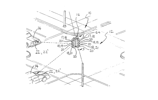
Referring to Figure 1, the traffic control
system 10 of the present invention is shown. The
traffic control system lo includes a road 12, a vehicle
14 traveling on the road 12 and a traffic light assembly
16 operatively associated with the road 12. The traffic
light assembly 16 comprises at least one traffic light
OL- lamp means 18 for providing an illuminated signal.
Typically, the traffic light assembly 16 includes red,
yellow and green traffic lights 17, 19, 21 for
projecting red, yellow and green light rays to signal
the driver of the vehicle 14 to "stop", "yield", or
"go", respectively. However, it is to be understood
that while an intersection control light is depicted in
216~37
Figure 1, the benefits of this invention may be applied
to a variety of other applications such as pedestrian
crossing signals, e.g. WALK, DON'T WALK signals or any
other illuminated "traffic related" message for
controlling traffic or simply providing information.
As shown in Figures 2 and 3, the preferred
embodiment of each traffic light or lamp means 18
includes a plurality of light emitting diodes 24 for
transmitting light rays from the traffic light assembly
16. In other words, the red traffic light 17 comprises
a first set of light emitting diodes 17A for projecting
red light rays, the yellow traffic light 19 comprises a
second set of light emitting diodes l9A for projecting
yellow light rays, and the green traffic light 21
comprises a third set of light emitting diodes 21A for
projecting green light rays. Each traffic light 18
further includes d.c. power connection means 26 secured
to the traffic light 18 and electrically coupled to the
diodes 24 for receiving d.c. power. The traffic light
assembly 16 also includes a.c. power connection means 28
secured to the traffic light 18 for receiving a.c.
power. The traffic light assembly 16 further includes
d.c. power supply means 30 secured to each traffic light
18.
216903~
Referring to Figure 4, d.c. power supply means
30 is electrically coupled to and between the a.c. power
connection means 28 and the d.c. power connection means
26 for converting a.c. power received by the a.c. power
connection means 28 to d.c. power so that d.c. power is
supplied to said d.c. power cnnnection means 26. D.c
power supply means 30 may be of conventional linear or
switchmode design. D.c. power supply means 30 includes
a step-down transformer to bring the a.c. line voltages
of 120 - 140 volts down to ap~oximately 3.5 volts and
a standard full or half wave rectifier to convert the
a.c power to d.c. power.
The traffic light assembly 16 is characterized
by a battery 32 removably ~onn~cted to the traffic light
18 for supplying d.c. power to said d.c. power
~onnPction m~ 26 to illuminate the diodes 24.
Preferably, the battery 32 is rechargeable. For
example, battery 32 could include any sealed lead -
acid, nickel - metal hydride, or lithium rechargeable
batteries. The traffic light assembly 16 further
comprises battery charger means 33 secured to the
traffic light 18 and electrically coupled to and between
the a.c. power connection means 28 and the d.c. power
connection means 26 for recharging the battery 32.
` - ~ 1 6 ~ 7
The interco~nection of the hAckllr battery 32
with the traffic light 18 is shown in Figure 4, and
essentially provides for a parallel power source with
the d.c. power supply means 30. Ordinarily, the ouL~uL
voltage of d.c. power supply means 30 would be the same
as the rated operating voltage of the traffic light 18
and the nominal voltage of the battery 32. That is, if
the traffic light 18 were designed to operate at 12
Volts, then the battery 32 would also have a 12 Volt
10 ~uL~uL and would be charged at a comparable (slightly
higher) voltage from battery charger 33. The battery 32
does not supply power to the traffic light 18 until a
power failure, i.e. until a.c. power from utility lines
is no longer being supplied to a.c. power connection
means 2B.
Whenever a.c. utility power fails, the entire
function of the st~n~rd traffic ~ollL ~ller is
compromised in addition to failure of the traffic lights
~h~mC~lves~ Unless a ~ellL ~1 uninterruptible power
supply is used to power both the traffic l~ghts and the
~ollLLoller, the lights may not be operated because the
critical timing function and seguenclng normally
provided by the controller is not available. Iherefore,
a specific aspect of this invention is to provide a
: 21690~7
safety default condition whereby all the red stop lights
at an intersection are flashed whenever a.c. utility
power fail~. The default condition effectively
establi Ch~ a four-way stop under battery power.
To implement the four-way stop default
condition, traffic light assembly 16 further comprises
a.c. power monitoring circuit means 34 secured to each
traffic light 18 for monitoring a.c. power supplied to
the a.c. power connection means 28. A.c. power
monitoring circuit means 34 is prefera~ly included as
part of a power pack 35 which also includes battery 32.
The power pack 35 may be attached to each traffic light
18 by various means. Monitoring means 34 monitors the
lamp current at all the traffic lights (red 17, green 19
and yellow 21) of the traffic light ~ ~hly 16. The
traffic light assembly 16 further comprises switch means
36 secured to each traffic light 18 for electrically
coupling ~he battery 32 to the d.c. p~.JeL CQnneCtion
means 26 in ~e~-L~ e to a trigger signal from the a.c.
power monitoring means 34 prompted by a predetermined
~ecrease in a.c. power supplied to the a.c. power
connection means 28. The traffic light assembly 16
further comprises pulsating circuit means 38 secured to
each traffic light 18 and electrically coupled to the
2169037
t
switch means 36 for causing the switch means 36 to
electrically couple the battery 32 to the d.c. power
connection means 26 at a predetermined frequency to
illuminate the diodes 24 at the predetermined frequency.
Preferably, the pulsating means 38 is included as an
integral part of the power pack 35. If monitoring means
34 detects a loss of power to all traffic lights 18 of
traffic light assembly 16, switch means 36 connects the
battery 32 to traffic light 18 and pulsating means 38
causes traffic light 18 to flash at the predetermined
frequency. Preferably, only the red traffic light 17 is
connected to the battery 32 upon a power loss so as to
create the default fl~hing red condition. A typical
flash duty cycle of 30% will extend the battery 32 life
cycle to a~oximately 12 hours for a 24 Watt/Hr rated
battery 32. Thus, the present invention allows low
cost, autonomous, rechargeable battery packs to be
~dapted to L.E.D. ~ traffic lamps in order to
provide low cost eme~yel~y operation when line power
outages occur, and to recharge automatically upon
resumption of utility power.
A small, low power radio transmitter 40 may be
~ecured to the traffic light 18 to advise a central
traffic engineering office of power outages or other
21~80~7
problems. The radio transmitter 40 is electrically
coupled to the switch means 36 for transmitting a radio
wave in response to the trigger signal sent by
monitoring means 34. As shown in Figure 3, a digitally
encoded radio transmitter 40 can be used to identify the
location of the malfunctioning traffic light assembly
16. Alternatively, a cable modem could be used to relay
this information. The traffic light assembly 16 may
include delay means 42 secured to the traffic light 18
and electrically coupled to the radio transmitter 40 for
delaying the transmission of the emitted radio wave a
predetermined time after the switch means 36 receives
the trigger signal. This delay is needed so that one
radio frequency may be utilized by a number of traffic
light assemblies without radio frequency collision by
any two traffic light assemblies.
In the most simple configurat~on, all the
diodes 24 can be arranged on a disk, plate or printed
circuit substrate so that all of the diodes 24 are
oriented in the same direction. Preferably, the diodes
24 are mounted on circuit board means 44. Circuit board
means 44 comprises of a planar printed circuit board
which includes ~ Lion means for electrically
coupling the diodes 24 in a plurality of æeries circuits
2~6~7
12
r
46 and for electrically coupling the series circuits 46
in parallel. Each series circuit 46 includes an equal
number of light emitting diodes 24.
S Each traffic light 18 further comprises a
traffic light housing 48. The light housing 48
comprises a hollow member 50 having a front open end 52
and a rear open end 54. The light housing 48 further
comprises a front cover 56 for covering the front end 52
and a rear cover 58 for covering the rear end 54. The
diodes 24 are mounted within the hollow member 50
between the front and rear covers 56, 58. The front
cover 56 comprises a transparent glass or plastic
material having a smooth outer surface 62. Transparent
glass is neCpcc~ry to allow light rays emitted by the
diodes 24 to exit virtually unimpeded and smooth surface
62 is preferred to avoid accumulation of dust and dirt.
The front and rear ~e~ 56, 58 form a hermetic seal
with the hollow member 50. The traffic ~oilLL~l system
10 further comprises an assembly housing 64 for housing
each traffic light 18. Each traffic light 18 further
includes mounting means 66 for removably mounting each
traffic light 18 to the assembly housing 64.
: 2169037
The traffic light 18 is retrofitted to permit
the use of the light in existing traffic light assembly
housings currently used to house incandescent traffic
lights. For ease of implementation, the traffic lights
S 18 are preferably used with existing traffic light lens
filters, which are normally stippled or equipped with
small lensatic elements to achieve correct beam
dispersion. These lens elements are ordinarily designed
to operate in con~unction with a reflector and the quasi
point source of a filament lamp. ~hile a planar array
of L~E~Dos w ll operate satisfactorily with existing
filters and lenses, a more effective lens is needed to
"fill-in" or illuminate the spaces between diodes 24 and
to steer the light rays emitted from the diodes 24 to
the intended target, such as the vehicle 14, to avoid
wasting any light energy. To this end, each traffic
light 18 may include one or more refractive elements 68
positioned between the diodes 24 and the front cover 56.
Refractive elements 68 act as a light ray steering means
o steer the light rays emitted by the diodes 24 to the
int~e~ target. Alternatively or in addition to
refractive elements 68, a spacer member 70 positioned
between said circuit board means 44 and the diodes 24
can be used to point the diodes 24 in a particular
direction. The spacer member 70 includes an angled
~ 2169~37
14
surface 72 against which the diodes 24 a~ut to
physically angle the diodes 24 relative to the road
surface 12.
Another aspect of this invention relates to
~he ability of L.E.D. lamps to be pulsed at high rates;
i.e. to be turned on (illuminated) and off (not
llluminated~ at high rates. By pulsing L.E.D.'s at high
rates, data can be optically transmitted from the
traffic light 18 to a remotely located photodetector.
Thus, the diodes 24 can be used to transmit information
to vehicle 14 such as announcing the presence of a
traffic light and transmitting map coordinates, street
names, directions or even traffic advisories. Existing
inc~n~e~cent tra~fic lights cannot be used to transmit
digital data because the th~r~ ~ inertia of the
filaments in these lamps precludes the rapid modulation
of the supply current to obtain detectable changes in
light ~L~L. Obviously, slow on - off modulation of
these lamps would be impractical as it would be annoying
and confusing to drivers. The perceived luminosity of
L.E.D. sources is a function of the average current that
powers the L.E.D. For example, a d.c. value of 20mA
might yield roughly the same perceived l~ osity from
a L.E.D. as a square wave tSO% duty cycle) of 40mA peak
2169037
current. The actual modulation of L.E.D. traffic lamps
is rather simple, except for the fact that the perceived
luminosity of the lamps needs to be essentially
constant, as their main function is to visually alert
drivers. Message transmission is a secondary function
that must not interfere with normal use. If the
perceived luminosity of each traffic light is to remain
constant during operation, the average current delivered
to the respective diodes must be essentially constant
for periods greater than approximately 30 millisec~n~.
This period corresponds to a flicker frequency of about
33Hz, ~hich is perceptible by some humans.
Pulsing the diodes 24 of the traffic light 18
allows ~he remote detection of the light rays
illuminated thereby as well as the identification of the
light rays, i.e., whether the red, yellow, or green
traffic light 17, 19, 21 is on. To distinguish whether
either the red, yellow, or green traffic light 17, 19,
21 is illuminated, system 10 comprises a transmitter 20
including means for optically transmitting data from one
of the traffic lights 18 of assembly 16 by turning the
first, ~co~, and third set of diodes 17A, l9A, 21A on
and off at three distinct fre~e~cie~ For example, the
first set of light emitting diodes 17A of the red
2169~37
16
traffic light 17 can be illuminated at 50 ~Hz, the
second set of light emitting diodes l9A of the yellow
traffic light 19 at 65 KHz, the third set of light
emitting diodes 21A of the green traffic light 21 at 9o
RHz. In this manner, the traffic lights 17, 19, 21,
continue to serve their primary function of visually
alerting drivers to stop, yield, or go while allowing
the remote detection and identification of the lights.
The system 10 further comprises receiver means
22 located at a location remote from the traffic light
assembly 16. For example, the receiver means 22 can be
disposed on the vehicle 14, as shown in Figure 1, for
optically receiving the data transmitted by the
transmitter 20. The receiver means 22 further includes
photo-detector means for converting the light rays
emitted by the red, green, and yellow traffic lights
into first, ~CQ~ and third ~uL~L signals of electric
current having first, ~cnn~ and third u~L~
frequencies, ~e~e~Lively. The receiver 22 further
~ncludes differential means for differentiating the
first, ~eco~ and third output frequencies from each
other to determine whether the red, yellow or green
traffic light is illuminated. ~he receiver 22 can be
- 2~G90~7
battery powered, or powered ~y the electrical system of
the vehicle 14.
Within the scope of the present invention and
S in addition to simple red, yellow and green light
detection, the system 10 may include digital data
transmission capability from the traffic light 18 to the
vehicle 14. One or all colors (red, yellow, green and
any turn signals, pedestrian messages, etc.) could be
driven by a digital code generator to relay a message to
oncoming vehicles, other traffic lights, or a central
traffic center. Typically, each traffic light (red 17,
yellow 19, and green 21) is "on" exclusively for a
certain time, therefore all traffic lights 17, 19, 21
facing one direction could share the same message
generator which would then transmit the same digital
code for each color change. Alternatively, each
indiviaual traffic light 18 could be coded with a
"color" precursor code to permit more sophisticated
~co~ng schemes at the remote receivers 22. The data
rate must be sufficiently high as to enable digital
message transmission within a single flash of a fl~hlng
red or yellow traffic light 17, 19 in order to
accommodate virtually all traffic signal contingencies.
~25 The most a~L~-iate use for such traffic light message
: 2~69~37
18
transmission capability would be audible routing
directions. For example, upon approaching a given
intersection, the vehicle mounted receiver 22 might
announce, ~Eastbound Metro Parkway at Hayes". No
directional ambiguity exists because the message is only
directed at oncoming traffic. Obviously, the
transmitter 20 would have to be programmed to deliver
the correct message, but this need be done only once, as
the light rer-; n~ at the same location for many years.
If an L.E.D. lamp i5 required to maintain an
essentially constant, perceived o~u~, the modulation
imparted to the L.E.D. must be sufficiently fast and
exhibit a constant average duty cycle. Several digital
modulation schemes are capable of this limitation.
Pulse position modulation (PPM), phase shift keyed (PSK)
modulation and frequency shift modulation (FSK) are
typical forms of an essentially constant duty cycle
modulation. The F.S.K. modulation scheme is shown in
Figure 6, as it is among the simplest to implement, and
it is widely employed in wired and wireless
communication links. Two distinct frequencies Fl and F2
are used to signal the digital l's and 0's or mark and
$pace data that constitute the message or data to be
transmittea. The advantage of using such a digital
" 2~69~37
" 19
modulation scheme is that the average L.E.D. lamp
current (and power) remains essentially constant
irrespective of the data. The reason for this is
readily apparent in the diagram depicted in Figure 6
which indicates a constant 50~ duty cycle for any data
stream. The result of such modulation is that the
visible (perceived) brightness of the lamp is invariant!
while high rate digital data is being transmitted or
even when no data is transmitted (all l's or o~s).
Ideally, the F.S.K. frequencies Fl and F2 representing
the digital l's or O's would be separated by several
hundred Hertz or kilo Hertz to facilitate unambiguous
detection. Having the frequencies within a 10% band
would allow a single tuned input amplifier to act as
preselector ~ilter to the frequency detectors.
Operating the L.E.D. lamps in the 10 to 20 KHz range may
be advantageous. This frequency band permits easy
differentiation from high intensity ~chA~ge (H.I.D.)
lamps such as street lights or neon lights. These light
sources may have similar spectral characteristics as the
traffic lamps, and thereby interfere with reliable
detection of the traffic lights 18.
Referring to Figure 5, the transmitter 20 that
~odulates the traffic light 18 is powered by the d.c.
21~9~37
power supply means 30. A.c. power from a conventional
traffic light controller in turn powers the d.c. power
supply means 30. The transmitter 20 comprises a non-
volatile local memory tEEPROM) or one time ~ OYL ammable
S ~O.T.P.) memory chip 78 for electronically storing the
digital message to be transmitted. The message itself
could be coded in virtually any form such as ASCII or a
proprietary ~lrh~numeric code. Additionally, digitally
coded, compressed voice communication could be
transmitted along with the ~lph~numeric text or instead
of it facilitating the regeneration of high quality
voice messages at the remote receiver 22. The
transmitter 20 further comprises a microprocessor 72 for
controlling the removal of the digital message stored in
the memory c~ip 78. The microprocessor 7~ also controls
the tr~n ;C~ion of the digita~ message.
The transmitter 20 further includes a solid
state switch 80. The solid stat2 switch 80 converts the
coded digital message developed by the microprorecsor 72
into F.S.K. format and thereafter transfers the F.S.K.
modulated signal to the diodes 24 of the traffic light
18. In other words, the switch 80 cGnL~ols the power
from the d.c. power supply means 30 to supply power to
illuminate the diodes 24 for a predetermined duty cycle
- 216~0'~7
consisting cf an ~1~ period follo.~ed by an OF~ period
short enough to be humanly imperceivable. The
microprocessor 72 further includes modulator means for
varying the length of time of the duty cycle to transmit
the digital information. Microprocessor 72 also
includes signal processor means for maintaining a
constant ratio between the ON and OFF periods as the
length of time of the duty cycle varies. Signal
processor means includes means for establishing a first
lo length of time for the duty cycle to create a first
digital signal corresponding to a digital "1" and for
establishing a second length of time for the duty cycle
to create a second digital signal corresponding to a
digital "O". In other words, the first length of time
corresponds to frequency F1 and the second length of
time corresponds to frequency F2;
The traffic light assembly 16 may include
power sensing means 74 for sensing when d.c. power is
delivered from the d.c. power supply means 30 and a
reset generator 76 for resetting the microprocessor 72
each time d.c. power is delivered to the traffic light
18 to initiate a new digital message sequence. The
traffic light assembly 16 may also include ambient light
sensor means 60 for varying the luminosity of the diodes
21~9037
22
24 in response to ambient light variations. Ambient
light sensor means 60 includes a photodetector 60
coupled to a power control element 82. Power control
element 82 controls the quantity of power delivered to
the diodes 24 in response to the level of ambient light
detected by the photodetector 60. For example, at
night, the voltage of the pulses delivered to the
traffic light 18 may be reduced to decrease brightness
to further reduce power consumption while in bright
sunlight the sensor means 60 would cause t~e power
control element 82 to increase the voltage of pulses
delivered to the traffic light 18. The power control
element 82 could consist of a linear voltage regulator,
or a low loss high frequency pulse width modulation
(P.W.M.) controller, ~oth of which are commercially
available devices. Note that if pulse control is
utilized to control lamp brightness, the operating
frequency of such a device would have to be
significantly greater than the modulation frequency in
order to not affect the digital coding.
The companion receiver 22 receives the digital
information transmitted by the diodes 24. Referring to
Figure 7, receiver 22 consists of an optical wavelength
selective filter 84, a collection lens 86, and a
21~9~37
receiver photodetector 88 coupled to a tuned amplifier
go and a limiter 92. The photodetector 88 converts the
light rays emitted by the diodes 24 into an output
signal of electric current. The optical wavelength
selective filter 84 allows only selective frequencies of
light, such as F1 or F2, to reach the photo detector 88.
The collection lens 86 directs the light rays emitted by
the diodes 24 to the photodetector 88. The amplifier 90
amplifies the output signal. The amplifier 90 is
typically peaked to respond preferentially to the F.S.K.
frequencies employed by the transmitter 20. F.S.K.
detection may be advantageously provided by a receiver
microprocessor 94 which then also handles character
decoding (using nonvolatile resident memory) and the
message display functions. The receiver 22 further
comprises visual message display means 96 for visually
displaying the digital information transmitted by the
diodes 24. Typically, a liquid crystal, vacuum
fluorescent, L.E.D., or miniature C.R.T. display would
be used to display the message transmitted by the
traffic light 18. The receiver 22 may also be equipped
with a voice generation means 98 comprising a speaker
means 99 for audibly conveying the digital information
transmitted by the diodes; 24. For voice message
applications, dedicated voice synthesis integrated
`- 2~9~1
24
.
circuits would convert the digitized, transmitted voice
announcement back into human speech for review by the
driver. Modern linear predictive coding techniques and
specialized voice I.C.'s (as used in many toys) could be
used to simplify the delivery of audible messages of
several seconds duration.
Referring to Figure 8, a simplified alternate
receiver 22' is disclosed for use in detecting whether
10the red 17, yellow 19, or green 21 traffic light is
illuminated. Receiver 22' consists of an optical
wavelength selective filter 84', a collection lens 86',
and receiver photodetector 88' coupled to a tuned
amplifier 90' and a limiter 92'. The receiver 22'
further includes an alarm generator 100 for driving a
speaker 99'. As an example, the receiver 22' could be
set up to sound an alarm upon the detection of a red
light as transmitted ~y the first set of diodes 17A.
20Once the requisite hardware is installed in a
critical number of traffic lights 18 and vehicles 14,
the traffic control system 10 may be used to transmit
traffic advisory messages. That is, the system 10 need
not be limited to repetitive prerecorded messages. A
traffic light 18 positioned at specific points along a
` 2~9037
road 12, such as an intersection, may be directly
accessed by cable or a wireless link from a central
traffic authority to transmit messages to passing
motorists. One method to accomplish such a function
would be to download digital message data to selected
traffic lights 18 for subsequent relay to passing
vehicles 12. Time-out or "sunset" provisions in the
software or traffic light transmitter 20 hardware could
be implemented to erase messages that were no longer
pertinent.
Another use for the traffic control system 10
described herein involves the use of the digitally coded
traffic lights 18 as "signposts" for vehicular
navigation systems. Digitally modulated tra~fic lights
18 could serve as convenient, low cost sign posts for
vehicular navigation systems, where unambiguous location
is essential. Traffic lights are ubiquitous, and are
easily adapted to transmit digital location information
as well as other data.
The invention has been described in an
illustrative manner, and it is to be understood that the
terminology which has been used is intended to be in the
` 216~0'~7
26
nature of words of description rather than of
limitation.
Obviously, many variations and modifications
are possible in light of the above teachings. It is,
therefore, to be understood that within the scope of the
appended claims wherein reference numerals are merely
for convenience and are not to be in any way limiting,
the invention may be practiced otherwise than as
specifically described.