Note: Descriptions are shown in the official language in which they were submitted.
WO 95/10080 PCT/US94/10762
FORCE REFLECTING H~1PTIC INTERFACE
BACKGROUND
The present invention relates generally to an interface.
between an operator and a machine. It relates more specifically
to the field of such interfaces which present: a signal to a human
operator in contact with the interface. The invention relates
most specifically to an interface that presents or exhibits a
force signal to an operator, such as a human, or receives a force
signal from such an operator. Because a force signal is by
definition bi-directional, it can be said that the interface and
the user "exchange" a force signal, or "share'" it with each
other.
Machines are ubiquitous in modern life, and every machine
must be controlled, either directly or indirectly by a human
operator. The interface through which the operator controls the
machine and receives information from the machine should be as
easy to use as possible, in light of the functionality the
machine provides. Examples of such machines include slave
robotic machines that operate in an environma_nt different from
that in which the operator exists. Other machines include
machine tools for shaping materials, vehicles and powered
machinery. Computers are also machines, which manipulate data
representing, among other things, text (word processors); numbers
-1-
WO 95110080 ~ '~ PCT/US94l10762
_.. ~ ~.~
(spread sheets); records (data bases); geometrical constructs
(drawing and painting programs), etc.
The user may control and otherwise interact with such
machines through various devices, such as a lever, joystick,
mouse (having buttons and a tracking mechanism), exoskeleton,
keyboard, touch screen, digitized pad or tablet, head mouse, etc.
Typically, the user manipulates a "master" input device in the
user's local environment and the "slave" robot, typically in a
different environment, moves in accordance to the user's
manipulations. The configuration of the master device may or may
not conform to some degree to the conformation of the slave
device.
For a rigid body, such as a rod-like appendage of a machine,
the number of freedoms necessary to unambiguously specify its
relation to a reference frame is typically considered to be six.
Conceptually, three freedoms specify the location of a point on
the rigid body, relative to the reference frame, and three
additional freedoms specify the orientation of the rigid body
relative to the same, or an equivalent reference frame.
Components on master devices typically are provided with
numerous degrees of freedom of motion to permit varied motions by
the user. The number of such degrees can be from one to six or
more. These numerous freedoms are facilitated by numerous joints
and actuators. Thus, a master arm may have a hand portion, with
several fingers, each with several joints. The hand may be
joined through a wrist joint to a forearm section, joined through
an elbow joint to an upper arm section, joined through a shoulder
-2-
WO 95/10080 ' ~ ~ ~ ~ PCT/US941107G2
joint to a trunk. Considering the joint of a finger most distant
from the trunk, it's state relative to a reference frame can be
specified by six freedoms, three for its posit=ion and three for
its orientation.
However, the entire arm assembly may have many more than
these six freedoms, due to the numerous joints and their various
flexibili-ies. There may be several conformations of the other
elements of the arm that place the terminal finger digit in the
same state. Many, or all of the actuators that drive the arm may
contribute to establishing the state of a single freedom, such as
the location along one axis. Thus, the entire=_ arm itself has
many freedoms, more than six. However, only six freedoms of
motion are required to specify the Jtate of any rigid body
portion of the arm.
Certain of such master and slave machine systems, known as
force reflecting systems, provide actuators such that motions of
the master component through the various degra_es of freedom are
affected or constrained to some extent. Typically, the motions
are affected based on conditions in the environment of the slave
robotic machine, such as forces that the slave encounters. Thus,
the user, grasping or otherwise contacting the master machine,
experiences constraints on the freedoms of motion that relate in
some way to the slave environment, and thus, :receives a force
feedback signal. A teleoperator is such a device.
In certain instances, it is desirable for the user to feel
the forces as if the user were contacting the slave environment
directly, rather than remotely through the master to slave
-3-
tit G
WO 95110080 PCT/US94/10762
connection, including intervening stages. A system that
accomplishes this is sometimes referred to as a "force
reflecting" system. Such a force reflecting interface is also
referred to as a "haptic" interface because it relates to the
human system of touch. Typical design considerations for such an
interface include the fidelity of the position and force or
torque feedback, simplicity of structure, minimization of
backlash, independence of freedoms of motion, work space
conformation, stiffness, responsiveness, sensitivity,
minimization of the physical bulkiness of apparatus and the
bandwidth of its response. By bandwidth, it is meant, the range
of combinations of speed of response and force applied.
In addition to controlling traditional, physical machines,
it is known for human operators to control "virtual" machines and
environments, which are not physical, but rather are "embodied"
or reside in a computer model.
Simple examples abound in connection with common computer
tasks. For instance, using a computer drawing or painting
program, a user controls a group of virtual geometric objects
that can be moved relative to one another, created, destroyed,
altered, stretched, etc. Another example is the now familiar
"desktop" metaphor for showing a directory of computer files, and
for the user to provide instructions with respect to the
manipulation (copying, deleting, opening, modifying, etc.) of
those files. Within a word-processing program, the user
manipulates virtual controls to scroll through different parts of
the text of a document, to delete ("cut") certain sections and to
add ("paste") them elsewhere. There are many more examples.
-4-
WO 95110080 PCT/US94/10762
Basically, such examples include anything where a user affects
representations of data elements, as represented by the computer
interface.
More complicated examples include those in which a more
realistic environment is created, su as by using more
sophisticated visual renditions of objects and settings, and
projection devices sucra as helmets and special_ eyeglasses.
A user may interact with the virtual environment by means of
various physical input devices, such as have been mentioned
above. Sound may also be a part of the interface.
The virtual, or artificial environments rnay also recreate or
simulate real environments, and can be used for the practice of
skills, such as medical. surgery, geological excavation, dangerous
cargo manipulation, etc.
The various interactive systems may expand the abilities of
humans, by increasing physical strength, improving manual
dexterity, augmenting the senses, and by projecting human users
into remote and abstract environments, either real or artificial.
The remote environments can also be of a scale much larger or
much smaller than typical human scales.
Force reflecting systems can be differentiated from other
known simulations, such as graphical flight simulators, and
remote controls, by the provision of force feedback. To enhance
the user's perception of physical interaction with the slave
environment, more than visual and auditory cues are required.
Touch, is the only one of the five human sensf~s that provides a
-5-
WO 95/10080 ;~F ~' '~" '~ a,~ ~ i"_' PCT/US94/10762
two way interface with the environment. Using touch, a human can
affect the environment while at the same time, perceiving the
effect of the contact with the environment. Such direct feedback
facilitates the user's perception of presence or influence in the
slave environment. In effect, with touch, a force signal is
exchanged or shared between the user and the machine, just an
equal and opposite forces are shared by two people holding hands.
The purpose of the force reflecting master is to give a user
the sense that the user is touching an object that is not
actually in the local environment. The object, referred to below
as a "non-local" object, can be a real object being manipulated
by a physical slave machine, or it can be a representation in an
environment that exists only as a computer data model.
For an ideal haptic interface, the user would not realize
that he was touching an interface separate from the environment
to be manipulated. Specifically, a user would not be able to
distinguish between touching a real object and touching a virtual
object with the device. Further, the device would not encumber
the user. The ideal interface would exert no external force on
the user when the user is moving freely in space.
Hard surfaces, such as walls, should feel as stiff with the
device as they do in real life, even when contacted at high
velocity. Corners of solid objects should feel crisp. Compliant
surfaces should feel springy.
Some known attempts at constructing force reflecting
interfaces have used an "exoskeleton." An exoskeleton is worn by
the user and can often exert forces at several locations along
-6-
W0 95/10080 "'' ~ ~ ~ ~ PCT/US94/10762
the arms and/or fingers. See generally, B. A. Marcus, B. An, and
B. Eberman, "EROS Research on Master Controllers for Robotic
Devices," FIFTH ANNUAL WORKSHOP ON SPACE OPERATIONS APPLICATIONS
AND RESEARCH (SOAR '91) pp. 238 - 245, July 1991. There are many
constraints in the design of an exoskeleton device, because the
structure must attach to several locatians on the human body and
the exoskeleton joints must effectively be co-located with human
joints. Counterbalancing such structures, and designing stiff,
uncoupled transmissions for them is difficult. The structures
must be counterbalanced so that the user does not perceive them
as an artificial construct of the feedback system. The
transmissions must be stiff so that there is a feeling of direct
contact with the non-local environment.
Another type of force reflecting interface uses an
externally grounded joystick. Typical of these devices are the
traditional "hot-cell" manipulator systems and force reflecting
hand controller.
Thus the several objects of the invention include, to enable
human interaction with a non-local environment, either physical
or computer represented, with a high degree of realism. It is an
object to facilitate a high fidelity position and torque or force
feedback, so that the user has an accurate perception of the
conditions in the non-local environment. they user interface
should be transparent to the user and as unobtrusive as possible.
Implicit in this object is to minimize system backlash. It is
further an object to provide such an interface that permits user
action over a physically appropriate size of workspace, without
necessitating a bulky or overly complicated apparatus. It is
0. ~ t
.~, ~ i;J
WO 95/10080 PCT/US94/10'762
also an object to provide a device that responds quickly enough
to conditions in the non-local environment for a realistic
simulation, and which displays appropriate stiffness and
sensitivity, as well as a relatively large response bandwidth, so
that relatively quick motions can be perceived and imparted by
the user. It is also an object of the invention to display
discontinuous events, such as impact.
SLJMNLARY
In a preferred embodiment, the invention is an apparatus for
physically exchanging a force with a user in an environment local
to the user. The apparatus comprises a connection element for
physically connecting to a user's body member and a linkage
between the connection element and ground. The linkage includes
means for powering at least three independent freedoms of the
connection element relative to ground and means for maintaining
at least one independent freedom of the connection element
relative to said ground free of power. Up to three independent
freedoms of the connection element may be maintained free of
power, and up to five independent freedoms may be powered,
although the number of powered and free freedoms of the
connection element alone does not exceed six. The linkage may
also include three linked bearings, with two pairs of the three
bearings being orthogonal, such as a gimbal assembly. The axes
of the bearings intersect at a reference point. For instance,
the connection element can be a thimble, for insertion of a
user's finger, with the intersection point being inside the
user's finger, as connected to the thimble.
_g_
WO 95/10080 ~ ~' ~ ~ ~ ~ ~ PCT/US94/107G2
The linkage may also include at least two masses that are
movable relative to graund and each other and the connection
element, such that the center of mass among these items remains
substantially stationa~.-y relative to ground despite motion of the
connection element. The masses may constitute actuators, which
may be connected to a local grounded element 'through a single
cable transmission. Other user connection elements include a rod
or stylus, or thimbles sized to accept other :body members, such
as the head, buttocks, foot, hand, arm, leg, tongue and toe.
It is also sometimes beneficial to track the motions of the
freedoms that are unpowered. The ground may :be a portion of the
user's body other than that to which the connection element is
connected.
In another preferred embodiment, the powered freedoms are
tracked and a signal is generated based on the tracking of the
freedoms. The signal :is transmitted to a non-local environment.
The non-local environment may be a physical environment or a
virtual, computer resident environment.
In yet another preferred embodiment, the invention is an
apparatus for physical:Ly exchanging a force with a user in a
first environment that is local to the user. The apparatus
comprises a user connection element and a linkage for connecting
the element to ground. The linkage includes pair of quarter
gimbals with the connection element fixed to a rotational bearing
fixed to one end of one of the quarter gimbals. The free end of
the other~quarter gimbal is connected to an extension of one bar
of a five bar linkage. The five bar linkage is actuated by two
_g_
WO 95110080 .:~ ~ c~ PCT/US94/10762
actuators, each connected between a different one of the bars of
the linkage and a support that is more proximal to ground than
the actuators. The support is actuated with respect to ground by
a third actuator. The three actuators combine to power three
freedoms of the connection element. The gimbals combine to
maintain three freedoms of the connection element free of power.
Still another embodiment of the invention is an apparatus
for generating a signal at a specified point. The apparatus
comprises a pair of actuators that are both connected to ground
through the same cable. A linkage is also provided for
kinematically connecting both of the actuators to the specified
point. The actuators may both be connected between ground and
the specified point through a five bar linkage.
Another embodiment of the invention is an apparatus for
generating a signal representative of a force, in effect, a
virtual switch. The apparatus comprises a receiver for receiving
a signal representative of the location of a user reference point
relative to a user reference frame and a model for storing a
representation of: a non-local reference frame; the user
reference frame, relative to said non-local reference frame; and
the conformation of a, non-local environment comprising a switch-
type, spring-type element, relative to said non-local reference
frame. A comparator is provided for comparing the location of
the user reference point relative to the non-local environment.
A force generator is provided for generating a signal
representative of a force. The force signal is based on the
location of the user reference point relative to the non-local
environment and a set of force rules. The force rules include
-10-
WO 95110080 ~ ~ '~ ~ PCT/US94/10762
spring-force rules which specify a switch output force signal in
response to a location signal of the user reference point
indicative of a deflected conformation of the spring-type
element. The switch output force signal is specified by a non-
linear function. Thus, a realistic virtual switch is provided.
The invention may also include an operator that makes changes to
the representation of the non-local environment based on the
signal representative of force and the set of: force rules. For
instance, the representation of the switch changes location in
the non-local environment.
Another preferred embodiment of the invention is a similar
apparatus for generating a signal representative of a force,
where the non-local environment comprises a type of element which
changes its cross sectional area in response to a force in a
direction perpendicular to the plane of the area. Such an
element is defined as a "diagonal" type element. Such elements
include a bristle brush, or a sponge. With such an embodiment,
which is similar to the virtual switch embodiment, the force
rules include a spring-force rule that specifies a diagonal
element output force signal in response to a location signal of
the user reference point indicative of a deflected conformation
of the diagonal-type element. This simulates the feeling that a
user has when pushing against a deforming bristle head of a
brush. The operator for calculating change's to the non-local
environment based on the force signal specifies a change in the
representation of the cross-sectional area of a selected region
of said diagonal-type element. The non-local environment may
also include an indicia of the cross-sectional area of the
-11-
~~-~ ~.~~a~
WO 95/10080 PCT/US94/10762
selected region of said diagonal-type element, analogous to the
mark a paint filled brush makes when pressed onto a painting
substrate. The apparatus may also include means for storing this
indicia over time, thus storing a painted line of widths that
vary along its length, based on the force applied by a user. The
non-local environment may also include a plurality of such force
rules, analogous to different sizes and stiffnesses and shapes of
brushes.
In another preferred embodiment of the invention, the force
generator can generate forces based on the time history of the
location of the user reference point relative to the non-local
environment. The force rules include friction-type rules which
specify a friction output force signal in response to the time
history of the location signal of the user reference point
indicative of a change in position over time of the user
reference point.
Another preferred embodiment of the invention is similar to
the previous embodiment. The non-local environment includes a
representation of a drafting substrate over which the reference
point moves. The force rules, rather than specifying rules for
the moving reference point, specify force generating rules for a
substrate. A force generator is provided for generating a signal
representative of a force, based on the location of the user
reference point relative to the non-local environment and a set
of force rules. The rules include drafting substrate-force
rules, which specify a drafting substrate output force signal in
response to a location signal of the user reference point
indicative of a deflected conformation of the drafting substrate-
12-
WO 95/10080 ~ ~ ~ ~ PCT/US94I10762
type element. The apparatus may also include a non-local
environment reaction calculator that makes changes to the
representation of the conformation of the non--local environment
based on the signal representative of force and the set of force
rules. The drafting substrate type-element rule specifies a
change in the representation of a surface shape of a selected
region of the drafting substrate-type element. The surface
texture of the substrate may be included in the non-local
environment, and may be modeled as a rippled wall.
Another preferred embodiment of the invention is A method
for physically exchanging a force between an apparatus and a user
in a first, user-local environment, said method comprising the
steps of providing an apparatus as described .above, having a
connection element for physically connecting to a body member of
a user and a linkage between the connection element and ground.
The linkage comprises means for powering at least three
independent freedoms of the connection element relative to ground
and means for maintaining at least one independent freedom of the
connection element relative to ground free of power. The method
also includes the steps of connecting the connection element to a
body member of the user and powering the at least three
independent freedoms of the connection element.
Another preferred. embodiment of the invention is method for
generating a signal representative of force, such as for a
virtual paint brush. The method comprises the steps of receiving
a signal representative of the location of a user reference point
relative to a user reference frame. Another step is storing a
representation of: a non-local reference frame; the user
-13-
CA 02172825 2002-08-15
75338-5
reference frame, relative to the non-local reference frame; and
the conformation of a, non-local envix-o:nment comprising a
diagonal-type, spring-type element, relative to the non-local
reference frame. The location of the user reference point is
taken relative to the non-local environment. A signal is
generated representative of a force, based on the location of
the user reference point relative to the non-local environment
and a set of force rules. The force rules include spring-force
rules which specify a diagonal element output force signal in
response to a location signal of the user reference point
indicative of a deflected conformation of the diagonal-type
element. The representation of the conformation of the non-
local environment is changed based on the signal representative
of force and the set of force rules. The diagonal element
spring-type rule specifies a change in l~h~: representation of
the cross-sectional area of a selected region of the diagonal-
type element.
In accordance with the present invention, there is
provided an apparatus for physically exchanging a force with a
user in a first, user-local environment, said apparatus
comprising: a) a connection element (202) for physically
connecting to a body member (2002) of said user; and b) means
for physically linking said connection element to a reference
(118), said linking means comprising: i) means (120, 130, 140)
for powering at least three independent freedoms of said
connection element (202) relative to said reference (118); and
ii) means (203, 205) for maintaining at least two independent
freedoms of said connection element (202) relative to said
ref erence ( 118 ) unpowered .
In accordance with the present invention, there is
provided a method for physically exchanging a force between an
apparatus and a user in a first, user-local environment, said
-14-
CA 02172825 2002-08-15
75338-5
method comprising the steps of: a) providing an apparatus
comprising: i) a connectian element (202) for physically
connecting to a body member (2002) of said user; and ii) means
for physically linking said connection element to a reference
(118), said linking means comprising: A) mean's (120, 130, 140)
for powering at least three independeni~ freedoms of said
connection element (202) relative to said reference (118); and
B) means (203, 205) for maintaining at least two independent
freedoms of said connectian. elerr~ent (202) relative to said
reference (118) unpowered; b) connecting said connection
element to a body member o.f said user; c) powering (1318) said
at least three independent freedoms of said connection element.
In accordance with the present invention, there is
provided an apparatus for generating a signal at a specified
point, said apparatus comprising: a) a first actuator connected
through a cable to a ground; b) a second actuator connected to
said ground through said cable; c) means for kinematically
connecting said first actuator to said specified point; and d)
means for kinematically connecting said second actuator to said
specified point.
In accordance with the preserat invention, there is
provided an apparatus far sensing a ,passiti.on at a specified
point, said apparatus comprising: a) a first rotary position
transducer connected through a cable to a ground; b) a second
rotary position transducer connected to said ground through
said cable; c) means for kinematically connecting said first
rotary position transducer to said specified point; and d)
means for kinematically connecting said second rotary position
transducer to said specified point.
In accordance with the present invention, there is
provided an apparatus for generating a position at a specified
-14a-
CA 02172825 2002-08-15
75338-5
point, said apparatus comprising: a) a first actuator connected
through a cable to a ground; b) a second actuator connected to
said ground through said cable; c) means :for kinematically
connecting said first actuator to said specified point; and d)
means for kinematically connecting said second actuator to said
specified point.
BRIEF DESCRIPTION OF THE DRAWINGS
These and other features, aspects, and advantages of
the present invention will become better understood with regard
to the following description, appended claims and accompanying
drawings, where:
Fig. 1 is a schematic perspective representation of a
portion of a preferred embodiment of t:he invention, showing
three actuators and a linkage far providing an apparatus having
three powered and tracked freedoms of motion. The device also
includes a user contact assembly having t~aree free freedoms of
motion
-14b-
WO 95110080 ~ ~ ~ PCT/US94/10?62
Fig. 2A is a schematic perspective representation of a
portion of a preferred embodiment of the invention, showing a
three free degree of freedom gimbal and thimble being contacted
by a user's finger.
Fig. 2B is a schematic perspective representation of a
portion of a preferred embodiment of the invention, showing axes
by which the rotational aspect of the user connection element can
be measured.
Fig. 3 is a perspective representation of the embodiment of
the invention shown in Fig. 1, with one actuator removed, shown
from the reverse side.
Fig. 4 is a schematic perspective view of an actuator
connected through a capstan and a cable to a disk.
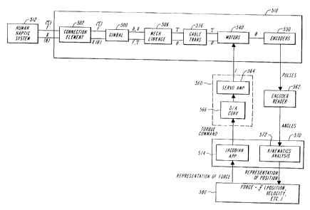
Fig. 5 is a schematic block diagram showing the exchange of
signals between the human operator and a computer control system
for the interface and a non-local environment.
Fig. 6 is a schematic perspective view showing a portion of
an embodiment of the invention having a stylus arrangement for a
user to grasp with three free degrees of freedom.
Fig. 7 is a schematic perspective view showing a portion of
an embodiment of the invention having a handle interface for a
user to grasp and exert torque with two free degrees of freedom
and with one powered degree of freedom.
Fig. 8 is a schematic perspective view showing a portion of
an embodiment of the invention having a wand interface that
-15-
WO 95/10080 PCT/US94/10762
allows a user to sense contact v.ith ~~irtual objects at :~a=ious
points along the length of the wand caith one free degree of
freedom and with two powered degrees of freedom.
Fig. 9A and Fig. 9B is a schematic representation of the
workspace for an embodiment of the invention as shown in Fig. ...
Fig. 10A is a schematic side elevation representation of the
embodiment of the invention shown in Figs. ~ and 3 with the user
connection assembly and the actuators at nominal home positions.
Fig. lOB is a schematic side elevation representation of the
embodiment of the invention shown in Figs. i and 3 in a position
where one of the actuators remains at the home position and the
other is moved from it.
Fig. 10C is a schematic side elevation representation of the
embodiment of the invention shown in Figs. 1 and 3 in a position
where the other of the two actuators remains at the home position
and the actuator at home position in Fig. lOB is moved from it.
Fig. 11 is a schematic perspective representation of a
user's fingers connected to three gimbal assemblies, with the
remainder of each apparatus not shown.
Fig. 12 is a block diagram showing schematically the
elements of an embodiment of the apparatus of the invention that
controls a virtual environment.
Fig. 13 is a flow chart representation of a method
embodiment of the invention for controlling a virtual
environment.
-16-
SUBSTITUTE SHEET (RULE 26)
WO 95/10080 ~ ~ ~, ~ ~ ~~ PCT/US94/10762
DETAILED DESCRIPTION
The present invention includes an apparatus that can be used
to interact with a "non-local" environment, either real or
virtual. The virtual environment can be of a typical computer
data processing type, or of a less common, more specialized type.
In one embodiment, a thimble is provided for engaging a
user's finger. The thimble is supported through a linkage such
that three freedoms of motion are provided for the user's finger
that are totally "unpowered." By unpowered, or "free of power",
it is meant that they are not powered, nor is there any
resistance (e. g. friction or damping) to motion through these
freedoms. (The status or position of motion through these
unpowered freedoms may or may not be tracked. If they are not
tracked, they are referred to herein as "free.") In the same
embodiment, the linkage is arranged such that three additional
freedoms of motion are "powered." By powered, it is meant that
the device has the capability to resist or asaist motion through
these freedoms, depending on the conditions in the non-local
environment and, typically, tracks the user's motions with
respect to these three freedoms. It is possible although
typically not desirable to have a powered, but untracked freedom.
Therefore, that embodiment is not discussed.
In this specification, and in the claims, "non-local
environment" signifies an environment other than that in which
the user resides. The non-local environment may be a virtual,
computer generated or resident environment, o:r it may be the
environment of a slave machine. It may be, substantially °local"
-17-
WO 95/10080 r' ~ t ~ ' PCT/US94/10762
r~~~~~i~~~
in the conventional sense, for instance, a doctor may manipulate
a slave mechanism that is inside a patient's body in the same
room as the doctor. However, the doctor manipulates a master
device, rather than the slave device, which moves by virtue of
connections between the master and the slave devices. In this
context, the environment inside the patient's body is the non-
local environment, despite its physical proximity to the surgeon.
The invention may also be used with two (or more) human
operators, each engaging a different physical interface. Each
operator's interface is controlled by the invention to generate
forces and motions in response to the forces and motions
conducted by the operator in the environment of the other
operators) in question, as well as tracking the motions and
forces conducted by the operator in the environment that is local
relative to the interface. Thus, two human operators can be in
"virtual" contact with each other, each interface functioning as
both a conventional "slave" and a "master."
Another use for the phrase "non-local environment" is a
wholly computer generated environment that is representative of
data. The data can itself represent a physical situation,
although it need not. For instance, data reflecting a numerical
index that rises and falls, such as the average temperature for
each day, may be represented as a line graph. The non-local
environment is a rising and falling graph of the data. This
rising and falling graph can be "felt" and "examined" by a user,
just as other virtual objects represented in computer memory can
be felt.
-18-
WO 95/10080 ~ ~ ~ ~ ~ ~~ ~ PCT/US94/10762
As shown in Fig. 1, a user connection element 200 is mounted
at the end of a link 102. The user connection 200 is a gimbal
assembly that is free to rotate about the axis G1 defined by an
extension of the link 102, being mounted thereon through a
suitably frictionless bearing 103. The gimbal 200 is shown in
more detail in Fig. 2A.
A thimble 202 is supported by an end quarter-gimbal 204 so
that it can spin around an axis G3, which passes through one
barrel 206 of the end gimbal 204. The bearing 203, through which
the thimble 202 is mounted, is substantially frictionless. The
quarter-gimbal 204 is itself connected through a frictionless
bearing 205 to the barrel portion 212 of another, medial quarter
gimbal 210. The end gimbal 204 is free to rotate about axis G2,
which passes through the barrel portion 212, and which intersects
with axis G3 in the vicinity of the thimble 202. The entire
gimbal assembly 200, made up of the medial quarter gimbal 210 and
the end quarter gimbal 204 and-the thimble 202 is free to rotate
about axis G1, which passes through the barre:L portion 214 of the
medial quarter gimbal :?10. The axis G1 substantially intersects
with the other two axes G2 and G3 at a user reference point 222.
Thus, if a user inserts a finger 2002 into the thimble 202,
the user can rotate the finger about its long dimension, i.e.
about axis G3. The user can also swing the base of the finger
about axis G1, thus moving through a plane spanning between the
thumb and small finger of an outspread hand, with the palm facing
downward. Similarly the user can swing the b<~se of the finger
about axis G2, through a plane spanning between the palm and the
back of the hand. These freedoms of motion c<~n be considered to
-19-
WO 95/10080 ~ ~ f~ ~ PCT/US94/10762
describe the orientation of the user's finger 2002 with respect
to an independent reference frame, or a "ground."
An aspect of the invention is the realization that, for many
interactions of a user's fingertip and the real world, the
environment does not resist motions through these orientation
related freedoms defined above. Further, the finger's position
with respect to these freedoms is irrelevant to the user's
perception of the environment, and for the environment's reaction
to the user's finger activities. Essentially, the finger
interacts with the world at a point. Thus, it is not necessary
to provide apparatus to actively power these freedoms, or, in
some cases, to track the user's motions through or position with
respect to these freedoms. This aspect of the invention is
explained more fully below, after a brief discussion of the
apparatus characterized by some powered freedoms of motion and
some unpowered freedoms, in a typical embodiment.
The observation extends to interactions between all other of
a user's body members, including but not limited to the foot,
arm, tongue, head, buttocks, etc., and combinations of powered
and unpowered freedoms other than three powered and three
unpowered. In addition to interfacing with a computer using a
body member, a user may also have need to use an orifice,
including the mouth, for instance in situations of lower limb
paralysis. The observation also extends to the interaction
between some point type tools (pencil, stylus, scalpel, etc.) and
their environments as well as line-type tools (e. g. rat tail
file, sword and cane).
-20-
WO 95/10080 ~ ~ ~ ~ PCTIUS94/10762
As shown in Fig. 1, the user connection gimbal 200 is
supported freely rotationally upon link 102, which is hinged to a
pair of parallel links 106 and 104. The hinges 108 and 110,
joining the link 102 to the parallel links 104 and 106,
respectively, are as frictionless as possible. The two links 104
and 106 are connected to a disk 112 through a mechanism that is
shown partially in phantom in Fig. 1 and is explained in more
detail below.
The disk 112 is supported through a frame 114 from a base
116, which itself is supported by a grounded support 118. The
base 116 and frame 114 are fixed to each other so that they
rotate together through angle 81B, about axis B1. A bearing is
provided to rotatably support both, but is not visible in Fig. 1.
This bearing is also as frictionless as possible.
The ground, which is not shown, is the item which serves as
a frame of reference, relative to which all motions and positions
of the user connection element is measured. In the embodiment
shown, the connection element is the thimble 202. In many
applications, the ground is fixed relative to the earth, or the
user's local environment. Thus, it may be fixed to the floor, or
a wall, or furniture. However, this is not required. Another
portion of the user may, in fact be the ground. For instance,
the user's head, or hips, or chest may serve as the ground. The
ground may itself be observably "floating," such as a buoy in a
body of water, or other fluid, a floating balloon, or a moving
vehicle. What is important is that the ground is the reference
frame with respect to which motion and position of the connection
element is measured.
-21-
PG~n ~A,., .' ~ G ~ 6 2
i P ~:~,: , _ _
The connection to the grounded support 118 through the frame
114 and the base 116 permits motion of the gimbal user connection
assembly 200 around the axis B1. Because the joints 108 and 110
are hinged, it is also possible to move the gimbal assembly 200
in a straight line, rather than along an arc, for instance in a
straight line parallel to axis y as shown in Fig, 3.
No constraint or control or power assist has been mentioned
regarding motion of the base 116 around the axis B1. However, in
a preferred embodiment, an actuator 120 is provided, which can
actively control motion around this axis. ("Actuator" is used in
this specification to refer to a unit that is either a motor, or
otherwise exerts a force. The actuator is often equipped with an
encoder also, although, it need not be.) Briefly, the actuator
120 has a body portion 122 and an axle (not shown) upon which is
mounted a capstan 124. If current is provided to the actuator
(through wires not shown), the capstan spins on the axis relative
to the body portion 122. The body portion is rotationally fixed
by a support 125, which is fixed to the grounded support 118, so
the capstan 124 rotates relative to ground and the body portion
remains fixed. A cable 126 is wrapped around the capstan and is
anchored at either end 128 to the base 116. The cable is routed
such that when the capstan 124 rotates, it pulls the cable 126
around it, thus causing the base 116 to rotate. Consequently,
the frame 114 and the entire assembly described above also rotate
about axis B1. Thus, a torque can be applied to the base 116.
Fig. 4 shows in in detail a single actuator having an
encoder 441, a body portion 442 and a capstan 444, connected to a
-22/1-
wll:i.',
-" -;::~~r
v. .~. ,i ~ ~~ ~ c
v y ~ 1995
IPEA/v~ ~
disk 412 through a cable 436. This actuator and disk is similar
in principal to the three actuators 120, 130 and 140 and their
respective disks, as shown in Fig. 1.
The actuator 120 may also provide a position sensing capability.
S In a typical case, the actuator 120 includes a conventional
position encoder 121 that keeps track of the
-22/2-
~/ ~ ,~ T 6~
~P~/~,j~ a
relative rotary position between the capstan 124 and the body
portion 122. Thus, given the appropriate geometrical analysis,
the position of the base 116 about the axis B1 can be determined
and a signal representative thereof can be generated by the
encoder. Rather than an encoder, any suitable position
transducer may be used, such as a potentiometer, a resolver, a
hall effect sensor, etc.
As will be described in more detail below, an additional
actuator 140 is arranged to exert torque on the link 106 around
an axis B2 that passes through the center of the disk 112. The
body 142 and capstan 144 of the additional actuator 140 is
connected through a cable 136 to the disk 112 and also includes
an encoder, not shown, to keep track of the position of the
actuator about the axis B2.
Further, a third actuator 130 is also connected to the disk 112
through the same cable 136 and is arranged to exert torque on the
link 356 around the axis B2. The actuator 130 also includes an
encoder 131 to keep track of the rotational position of another
hinge joint (352, Fig. 3, 10A, not shown in Fig. 1) with respect
to the axis B2. Because of the geometry of the links 106, 104,
356 and the portion 101 of the link 102 that is between the hinge
joints 110 and 108, keeping track of this position of the hinge
joint 352 relative to the axis B2 is equivalent to keeping track
of the position of the hinge joint 108 with respect to the axis
B3. This is because the distance between the two hinge joints
110 and 108 is known, and, in this case is equal to the distance
between the hinge joint 352 and the axis B2, and because the
-23/1-
. ._'.;, .rn .~~_
IPE~Iv~ . ~~
arrangement of the links 104 and 106 is known, in
-23/2-
~':r...'_.'u ~ ~'~~.T
'~~T~r a
IP~~= .
this case, remaining parallel, as are the links 356 and the
portion 101 of link 102.
Although in the embodiment shown, the links 106 and 104 are
parallel, they need not be. Similarly, the links 101 and 356
need not be parallel or of the same length. All that is required
is that their relative lengths be known. Hinges are provided
between links 104 and 102, 102 and 106 and 106 and 356. The
links 106 and 356 both rotate around an axle bar 354, which is
connected to ground by being connected to the disk 112 and the
frame 114, which is connected to the grounded support 118.
Moving any one link constrains the motion of the other four.
However, the motions of the links would not be constrained with
respect to ground, but for the axle 354. Thus, the linkage is a
five bar linkage. Alternatively, the axle 354 can be fixed to
one of either links 106 or 356 and can be connected to the disk
112 through a rotary bearing.
Knowing the relative positions of the hinges, and the
geometry of the device, it is possible to precisely specify the
location with respect to ground of the user reference point 222
within the tip of the thimble 202 at which the axes G1, G2, and G3
intersect. Thus, the device can determine the location of the
user's finger tip.
As can be seen in Figs. 1, 3, and 10A, the actuators 130 and
140 are both connected to the disk 112 through a single cable
136. The disk 112 is mounted through the frame 114, such that i~
cannot rotate about the axis B2. Each actuator 130 and 140 is
mounted to a respective link 356, 106, such that the body pcr~a~n
-24-
t
~o,:~il
WO 95/10080 l"' ' ~ PCT/US94/10762
of the actuator cannot rotate relative to the link. If current
is provided to the actuator (through wires not shown), a relative
rotation is induced between the body portion and the respective
capstan, for instance the body portion 132 and capstan 134. The
cable 136 is wrapped around the capstan and anchored to the disk
112 at both ends such that when the capstan rotates, it pulls the
actuator around the disk, toward one or the other of the cable
endpoints. This differs from the normal use of actuators and
transmission elements, where the actuator remains stationary and
the transmission element moves relative to ground. The tension
of the cable 136 is provided so that the actuator moves in either
directions without slipping or binding. The figure eight
wrapping configuration of the cable (around the capstan and the
disk 112) allows f~~ higher tension with lower friction than a
conventional simple loop configuration. The cable could also be
terminated on the capstans.
Considering first the actuator 130, it is connected to a
relatively short arm 356 which is part of a box frame 355 that
pivots around the axle 354 that passes through the center of the
disk 112 along the axis B2. The short link 356 extends beyond
the center, to a hinged joint 352, at which the link 356 is
hinged to the longer link 104. The link 356 includes a portion
301, which extends from the axle 354 to the hinged joint 352.
The link 104 is connected to the link 102 from which the gimbal
user connection assembly 200 is suspended.
Thus, with the four links 301, 101, 106 and 104 arranged in
a nominal "home" position, to form a rectangle, (as shown in Fig.
10A) if the user moves the user connection assembly 200 generally
-25-
WO 95/10080 '~ ~ ~ ~' ~ ~ ~ PCT/US94/10762
perpendicular to the long axis of link 102 in such a way that the
hinge 108 moves in an arc around the hinge 110 and the hinge 352
moves in an arc around the axle 354 so that the assembly is in
the configuration shown in Fig. 10B, the short arm 356 will pivot
around the axle 354, and cause the actuator 130 to travel along
the cable toward the other actuator 140. The motion of the
actuator 130 results in a relative rotation between the capstan
134 and the housing 132, from which the position of the actuator
130 relative to the axis B2 can be determined. From the position
of the actuator 130, an aspect of the position of the user
reference point 222 can be determined.
If a current is applied to the actuator 130 and any torque
that is applied by the user is insufficient to resist it, the
actuator will move. Motion of the actuator 130 around the
perimeter of the disk 112 causes motion of the short arm 356 and
of the end of the link 104 that is hinged at 352 to the short
link 356, and, consequently, the other end that is hinged to the
link 102. Similarly, such motion causes a corresponding motion
in the user connection gimbal assembly 200.
The actuator 140 operates similarly. It is also connected
to the disk 112 through the same cable 136 by which the actuator
130 is connected. The actuator 140 is mounted to one end of the
link 106, which pivots around the axle 354 (axis B2) at the
center of the disk 112. (The link 106 extends beyond the axle
354 to the actuator 140 by virtue of an "L" shaped link extension
portion 306.> The link 106 is also connected through the hinge
110 to the end of the link 102, to which the gimbal assembly 200
is connected. Thus, motion of the user contact connection
-26-
WO 95110080 P' ~ ~ ~ PCT/US94/10762
r,n ,
assembly 200 from the nominal "home" position, shown in Fig. 10A,
in a direction generally parallel to the long dimension of the
shaft 102 (to the position shown in Fig. 10C), results in a
motion of the hinge 110 of the link 106 generally in an arc
around the axle 354. This results in the actuator 140 being
drawn around the perimeter of the disk 112, away from the
actuator 130. The encoder 141 of the actuator 140 can thus
determine its position around the axis B2. From this position,
an aspect of the position of the user reference point 222 can be
determined.
Similarly, if current is applied to the actuator 140, the
actuator will be urged to travel around the perimeter of the disk
112, resulting in the motion of the gimbal assembly 200 from the
home position to that shown in Fig. 10C.
Thus, it will be understood that, taking together the
position signals generated by each of the encoders 131, 141 and
151, connected to the actuators 130, 140 and 120, in combination
with the known geometry of the various links, the precise
position relative to the ground can be determined of the user ,
reference point 222 within the thimble where the axes G1, G2 and
G3 intersect. This location c~n be used by other parts of a
system. For instance, it can be used to determine the location
of a mapping of the user's fingertip relative to a virtual
environment in a computer. It could also be used to determine
the user's intention as to where to move a slave device located
in a non-local environment relative to locations in that non-
local environment.
-27-
WO 95/10080 '~°' -~ ~~ ~ ~ PCT/US94/10'762
The embodiment discussed above employs linkages that result
in three powered, tracked freedoms of motion and three free
(unpowered and untracked) freedoms of motion for the user's
finger tip. As mentioned above, by a powered freedom of motion,
it is meant that the mechanism can provide a resistance (or
assistance) to the user's attempts to exercise that freedom of
motion. In the embodiment illustrated, the powered freedoms are
also "tracked," meaning that the mechanism can also keep track of
the user's position with respect to that freedom. A powered
freedom can be either tracked or untracked, although it is
typically not beneficial to have an untracked, powered freedom.
A tracked freedom can be either powered or unpowered. In the
illustrated example, the powered freedoms are governed by the
three actuators 120, 130 and 140, which include both motors and
encoders. Considering a stationary reference frame as the
ground, the three powered freedoms can be considered to relate to
the position of the user's fingertip in a three dimensional
space, as indicated by the axes x, y and z in Fig. 3.
It should be noted that none of the three actuators, 120,
130 or 140 can individually power motion through any arbitrary
combination of the powered freedoms of translation relative to
the axes x, y and z. Rather, all act together to both power and
track such motion, Similarly, none of the three actuators can
individually provide a torque that establishes an arbitrary force
vector with respect to these three axes. Again, all act together
to establish such a force.
The free freedoms in this example can be considered to
define the rotational position of the thimble, with respect to
-28-
WO 95/10080 ~ ~. ~ ~ ~ ~' ~ PCT/US94/10762
the stationary reference frame. The rotational position is
measured with respect to the x, y, z frame translated to the
reference point 222, at which the axes G1, G2 and G3 coincide.
This translated reference frame is represented in Fig. 2B by the
axes a, b and c. Such a rotational position is measured relative
to a rotational rest position, for instance one in which the axes
G1 G2 and G3 coincide with the axes a, b and c, respectively.
There is a difference between these three axes a, b and c
and the axes G1, G2 and G3. The G axes are fixed to the
apparatus, and change their orientation depending on the relative
location of the gimbal elements. For instance, if the user
swivels the thimble such that its tip is pointing straight at the
link 102, then the axes G1 and G3 would coincide. However, the
axes a, b and c always remain orthogonal, and at the same
orientation with respect to the reference frame having an origin
at the origin of the axes x, y and z. The origin of the axes a,
b and c moves with the translation of the reference point 222 at
which the three G axes intersect.
The free freedoms of motion, in this example, are the
rotations of the thimble about the axes a, b and c. They are
facilitated through: the free spinning of the medial quarter
gimbal 212 about the axis G1; the free spinning of the end
quarter gimbal 204 about the axis G2; and the free rotation of
the thimble 202 about axis G3. These freedoms correspond to a
combination of swinging the finger from left to right, and from
palm to back of hand, and rotation of the finger about its long
axis. None of these freedoms can be impeded or aided by the
embodiment of the system shown in Fig. 1. In the embodiment
-29-
W0 95110080 ~ .~. ~ ~ PCT/LIS94/10762
shown, none of these freedoms are tracked or powered. Thus, the
user's motions through these freedoms are not sensed or recorded
or communicated to the non-local environment in any way. Nor
does that environment act upon them.
A principal aspect of the invention is the realization that
significant advantages can be achieved by limiting the number of
powered (and in some cases, tracked) freedoms to less than the
maximum number that are physically achievable. For instance, it
would be technically possible to provide motors and encoders for
each of the joints of the gimbal assembly, as well as the
rotating thimble, thus providing six powered freedoms for the
thimble. However, such an arrangement has drawbacks. Further,
it is not necessary to provide so many powered freedoms to
provide an apparatus that provides high fidelity force feedback
for many useful applications, particularly point-type and line-
type applications.
For instance, considering interactions between a user's
finger tip and the, physical world, most such interactions can be
considered to be point-type interactions, where the real world
does not apply a torque to the finger, but merely applies a force
vector at a single point. In other words, there are many
interactions where a user's finger is not twisted about its long
axis. Similarly, there are many interactions where only a
negligible torque is applied about two orthogonal axes that are
perpendicular to the finger's long axis. Further, since a finger
is fixed at one end, it cannot rotate freely about its center
about either of these two axes. Any limited torque applied about
these two axes can be faithfully modeled as a force, directed
-30-
WO 95/10080 PCT/US94/10762
either along a line from palm to back of the hand, or from thumb
to small finger or a combination thereof. The foregoing
considerations apply to such activities as pushing a button,
pulling a loop, pushing an object, probing, picking up objects
between thumb and finger(s), tapping and scratching, just to name
several.
Similarly, for such point-type interactions, the
translational position cf the fingertip is important, but the
rotational status of the finger is irrelevant. If a user presses
a simple button, the button will depress in the same manner
whether the user contacts the button with the fleshy portion of
the finger tip, or with the fingernail portion of the finger
(ignoring considerations of friction). Similarly, the button
will depress in the same manner no matter what the finger's
angular position to the button from left to right (thumb to small
finger) or up and down (back of the hand to the palm).
Thus, it is not necessary that the system be able to
influence such freedoms of ~he user's finger and the user
connection element 202, because a physical environment often does
not influence such freedoms. Similarly, it is not necessary for
the system to track the positions relative to such freedoms,
because the physical world will react the same to user activities
regardless of the positions relative to those freedoms. However,
it is important that the user be able to pass through such
freedoms, as is provided with the essentially frictionless joints
and gimbals of the connection assembly 200.
-31-
:. .~. ; ~5
WO 95/10080 PCT/US94/10762
To date, most known systems have either tried to provide
powered and tracked control for all freedoms that are experienced
atypically six for a rigid body), or have limited the number of
freedoms available, for instance by prohibiting rotation about
one axis.
Providing powered, tracked control over the maximum number
of freedoms requires a large number of actuators. The actuators
are relatively heavy and usually expensive. Controlling them
requires additional computational power and programming.
Additional transmissions are required to communicate with the
additional actuators. Their weight must be counterbalanced, or
otherwise accounted for so that the user does not perceive their
existence. This further adds to the complication and bulk of the
device. It also limits its ability to respond quickly to motions
of the user, thus resulting in a narrower bandwidth than is
desired.
There is another advantage to powering only three freedoms,
and to using an arrangement such as shown in Fig. 1, where the
user reference point falls within the user's body member
connected to the device, in this case, a finger in a thimble.
This arrangement allows the user to perceive sharp and small
objects. The user's haptic resolution is enhanced, because the
device acts as if the point of contact is within the user's body
member. The effect is analogous to the enhanced haptic
resolution achieved by removing a bulky glove and contacting an
object with skin surface, except that in this case, the haptic
resolution is enhanced by making it seem as if the user's muscles
-32-
WO 95/10080 PCT/US94/10762
and bone are directly exchanging the force, rather than the force
being mediated through the skin and intervening flesh.
Having described a preferred embadiment of the invention,
the general properties that it embodies will be explained. These
general properties may be achieved in a multitude of
configurations, all of which are within the contemplation of the
appended claims.
The actuators must be sized so that they can create forces
that simulate the type of non-local environment sought to be
replicated. The device should be able to exert a force large
enough so that the user can experience the stiffness of a surface
without saturating the actuators. This insures that the user
will perceive a wall as immovable. A high maximum force will
also enable the device to display impact force transients more
accurately (as when a slave device strikes a wall). The maximum
force that the device can exert should also be viewed in relation
to the back drive friction inherent in the device (discussed
below). It is desirable to have a high ratio of maximum force
exertable to back drive friction, because a higher ratio
translates to a larger dynamic range of forces the device can
exert.
As an example, the average maximum exertable force for a
human's index finger has been estimated to be on the order of 50
newtons and previous studies have suggested that 40 newtons is an
appropriate design maximum for a telerobotic handmaster. See
generally, P. H. Sutter, J. C. Iatridis and N. V. Thakor,
"Response to Reflected-Force Feedback to Fingers in
-33-
'CTr''
~- ~= ~ .~ m a r 6 z
21 7 2 8 2 5 IPEA:~1JS o ~ SEP 1995
Teleoperations,° Proc. of the NASA Conf. on Space T,~lPrnhr,r;~~,
pp. 65-74. NASA JPL, January 1989. However, it has been
discovered that a lower force capability provides acceptable
performance. For instance, an actuator that can exert a maximum
force of only 8 newtons can be used in a system that can create
the illusion of a solid wall.
For the embodiment shown above, with actuators that move as
part of the counterbalance system, using smaller actuators
permits faster response, higher bandwidth, and more flexibility
in counterbalancing. It also minimizes the risk of harm or
discomfort to the user. Using smaller actuators also facilitates
meeting two additional desirable design criteria, that of
minimizing back drive friction and of reducing the inertia of the
device.
The device should have as little back drive friction as
possible. Friction adds noise to the forces that the device
attempts to present (reflect) to the user. It also creates a cue
to the user that the non-local world is not natural. Significant
friction can cause user fatigue. As has been mentioned above, it
is desirable for the ratio of maximum force to back drive
friction to be as high as possible to facilitate a wide dynamic
range. Therefore, it is desirable for the friction to be as low
as possible, particularly since it is also desirable to minimize
the maximum exertable force needed.
In a typical device, friction can come from at least three
sources: the bearings in the structure, the transmission from the
actuators to the linkage, and the actuators themselves. The
-34-
AN~ND~D ~ia~ET
WO 95/10080 - ~ PCTIUS94/10762
friction in the bearings and the transmission can be made very
low. Therefore, the actuator technology places a lower limit on
the friction that can be achieved, and thus, the upper limit on
the ratio of maximum force to back drive friction. Although the
ratio of maximum force to friction force may be fixed by a choice
of actuators, the particular operating range of the forces is
determined by the transmission ratio.
The device should also have a low inertia. The inertia of
the device will not cause a significant problem if the user moves
at a constant velocity. However, if the user accelerates or
decelerates, the inertia of the system that is not an aspect of a
physical system will give the user the undesirable sensation that
an external mass is being borne by the user. Additionally, the
inertia of the device also limits the bandwidth with which the
device can respond to commands. Typically, all devices are
capable of providing small forces rather slowly, or at steady
state. Thus, it is the ability of the device to provide a
relatively large force quickly that determines the bandwidth. It
has been determined that, for a finger operated interface, it is
beneficial to maintain the apparent mass felt by a user wearing
the device to less than 100 grams. The apparent mass felt by the
user is proportionally related to the inertia of the structure
plus the reflected inertia of the motor. The reflected inertia
of the motor armature is proportional to the transmission ratio,
N, squared.
The device should be statically balanced at all points
within its operating space. As with friction, an external force
created by gravity acting on some unbalanced portion of the
-35-
WO 95/10080 s -~ :~ ~ ~ ~~ ~ PCT/US94/10762
~~ t
device can pollute the forces that the user experiences. Also, a
constant offset in force can quickly lead to fatigue for the
user. It is possible to actively compensate for imbalances in
mechanical structure, however, this requires compromising the
dynamic range of the actuators in the system. It is desirable
for the balance to be maintained through a wide range of
orientations with respect to ground. For example, as discussed
below, the embodiment of the invention shown in Fig. 1 is
statically balanced within 10 grams whether the base 116 is
located gravitationally above or below the user connection gimbal
200.
There should be very little backlash in the transmission for
several reasons. First, if the location of the user reference
point of the device is to be calculated from the position of the
actuators, the error in the calculated position will, at a
minimum, be equal to the play in the transmission. Second, the
backlash introduces a discontinuity in the force transmitted from
the motors to the user contact assembly. While in the zone of
backlash, the user does not feel the load of the motor on the
other end of the transmission. However, as the user or the motor
moves the device out of the backlash zone, a stiff transition is
experienced as the motor is once again engaged. The non-
linearities introduced by backlash also tend to destabilize some
servo algorithms.
Small changes in finger position are easily discerned by
human users. Even positional variations of less than 0.01 inches
(.254 mm) can be discerned and are thus unacceptable. Further,
the force non-linearities created by backlash in the transmission
-36-
WO 95110080 ~ ~ ~ PCT/US94/10762
are difficult to model and therefore make force control
difficult. Thus, a system with zero backlash should be used.
The stiffness of the structure, transmission and the servo
control loop determine the overall stiffness and bandwidth of the
device. The stiffness of the structure and transmission can be
made very high. Therefore, the limiting stiffness for the device
disclosed is the servo-loop.
The maximum closed loop stiffness achievable with the stable
servo-loop is a function of the inertia of the device, the
impedance of the user's finger attached to the device the
transmission ratio, the servo rate and the encoder resolution.
Typically, the transmission ratio is the easiest of these factors
to vary.
Finally, the position resolution of the device should be
high, for two reasons. First, a high resolution enables the
device, to reflect finer position details of a virtual
environment. Second, the resolution of the encoders sets a limit
on the stiffness of the control loop which can be closed and
similarly limits the generation of viscous and inertial effects.
A preferred embodiment of the invention, as described above,
accommodates the conflicting specification needs of the haptic
system, discussed above. It uses three powered, tracked freedoms
of motion and three free freedoms of motion. As has been
discussed above, this provides for a faithful rendition of the
interaction between a user's finger tip and the real world for a
wide variety of finger activities. The device can exert and
resist a Cartesian force vector with the user's finger, by using
-37-
WO 95/10080
PCT/US94/10762
the motors to exert a torque upon the device joints. A data
processing unit, shown schematically in Fig. 5, calculates the
required motor torques by multiplying the Cartesian force vector
by the transpose of a jacobian matrix, which relates the torques
in the motors to the force at the user reference point 222 based
on the geometry of the system and the positions of the actuators.
In order to size the actuators, the range of the workspace,
and thus, the lengths of the links 106, 104, 102, must be
selected. For the embodiment discussed above, the device has the
first actuated joint located generally above the location of the
user's wrist during use, and the sizes of the other elements
allow users to move the wrist, knuckle and finger joints to all
extremes without exceeding the workspace of device. The base
disk portion 116 has a diameter of 4.5 in. (11.43 cm.). The disk
112 has a diameter of 3 in. (7,62 cm.). The length of the links
between axis B2 and hinge 110 is 5.5 in. ((13.97 cm.) and the
length of the link between the hinge 110 and the intersection
point 222 is 5.5 in. (13.97 cm.) and the distance between the
hinges 110 and 108 is 1.25 in. (3.175 cm.).
With respect to the actuators, given a desired range of
motion, a desired maximum exertable force and a transmission
ratio, the necessary peak torque for the actuators can be found.
Suitable actuators, weighing 130 grams, with a peak torque of 24
newton-centimeters, are available from Maxon, Inc., of
Switzerland, under trade designation RE025-055-35EBA 201A. The
motors use an ironless armature technology, which reduces torque
ripple and minimizes the armature inertia. A high resolution
encoder suitable for use with the selected actuator provides
-38-
~a~.~~28~~
WO 95110080 PCT/US94/10762
2,000 counts per rotation, and is available from Hewlett-Packard
of Palo Alto, CA under model number 5310.
In general, gear reduction transmissions available are
subject to greater backlash than desired, as set forth above. A
"direct-drive" may be used in certain circumstances. However,
this requires using motors with a high stall torque. This would
require using excessively large, heavy motors, which would result
in large inertia and a generally bulky apparatus. Thus, for a
system that simulate interaction of a user's finger with the
physical world, a direct drive system has drawbacks. However,
for a system that simulates interaction with a larger member, for
instance a user's fist, or foot, such a drive may be suitable.
A cable transmission can meet the zero backlash
specification with very little friction, and can also provide a
transmission reduction. The backlash can be made zero by
pretensioning the cable. Use of a cable transmission requires
consideration of several factors. The cable routing should be
such that radial forces on motor and capstan bearings are
minimized. Cables that are wrapped around pulleys more than one
full turn require a finite capstan width, because they "walk"
across the capstan as it spins. The tension which a drive
capstan c~~ maintain on a cable is proportional to eNe where ~1 is
the coefficient of friction between the cable and the capstan and
A is the angle through which the cable is wrapped around the
capstan.
Cables have a finite minimum pulley radius around which they
may travel without creating friction and being significantly
-39-
,, ..
WO 95110080 PCT/US94/10762
fatigued. For instance, for cables sold by Sava corporation
under trade designation ST-2032, suitable for use with the
embodiment described above, .028 inches (0.71 mm) in diameter,
the minimum radius is 0.2 in. (5.08 mm). Transmissions should
S avoid excessive free lengths of cables over long spans. Long
lengths of free cables introduce compliance into the
transmission. Further, pretensioned lengths of cables act as
energy sources, which can lead to unwanted resonances at certain
frequencies. Finally, it is often helpful to add a spiral groove
to capstans. This insures that the cable travels in the same
manner each time and that wraps of the cable do not scrape each
other. This groove also effectively increases the friction
coefficient between the cable and capstan, as well as also
reducing the fatigue in the cable, both of which are desirable.
The embodiment of the invention shown generally in Fig. 1
provides an elegant arrangement by which the elements of the
invention counterbalance each other to provide a static balance
and to minimize inertia. It also simplifies the transmission.
The motor 120, which actuates with respect to axis B1, is
stationary with respect to ground, and therefore, it does not
contribute to the inertia of the device. However, the base 116,
which forms part of the transmission with the actuator 120, does
contribute to the inertia of the device around axis B1.
Therefore, it is beneficial in some instances to remove a portion
(for instance, one half) of the disk that is not necessary for
the transmission, in order to reduce the inertia. Such a
configuration may not be balanced for all orientations, and
-40-
WO 95/10080 PCT/US94/10762
therefore, it is not beneficial to use a partial disk in all
situations.
The location of the two actuators 130 and 140, which
cooperate to actuate motion in a plane perpendicular to axis B2,
act as counterweights to other portions of the assembly so that
they substantially balance the structure statically at all points
within the workspace. (Actually, the device is statically
balanced to within 10 grams at all locations.) An advantage of
this configuration is that it does not add any unnecessary mass
to the apparatus to accomplish that static balance.
The means by which the counterbalance is achieved can be
seen with reference to Figs. 10A, 10B and 10C. The center of
mass of the actuators 130 and 140, the links upon which they are
carried, 356 and 106, the link 104, which is parallel to link
106, and the link 102 and gimbaled user contact assembly 200
remains at the axis B2. For instance, if the link 106 is kept
stationary with respect to the disk 112, actuator 140 is also
kept stationary. If, at the same time, the gimbal assembly 200
is moved (as viewed in Fig. 10A) generally counter clockwise
around axis B2, to the position shown in Fig. 10B, the link 104
and the short link 356 move such that the actuator 130 is drawn
counter clockwise around the disk 112 and the axis B2. The
lengths of the links and their masses are selected such that for
a given relative motion, which is governed by the geometry of the
links, the center of mass remains substantially at the axis B2.
Similarly, motions of the gimbaled assembly 200 that cause
rotation of the long shaft 106 around axis B2, such as is shown
-41-
~, : r~~ c~~
WO 95/10080 w' a ~ ~ ~ ~ ~ PCT/US94/10762
in Fig. 10C, cause a corresponding motion of the actuator 140
around the same axis B2, substantially counterbalancing the
weight of the portions of the assembly on the other side of the
axis B2.
The two instances of counter balance discussed separately
above, work together, so that any motion of the gimbal connection
assembly 200 is counterbalanced by corresponding motions of both
of the actuators.
In a preferred embodiment, only one cable 136 is used for
both of the actuators 130 and 140. This has the advantage that
it is necessary to install and pretension only a single cable for
the two actuators. Further, the cable is routed so that
pretensioning adds minimal axial and radial loads to the motor
bearings.
The size of the drive capstans and the size of the shared
pulley 112, upon which both the actuators 130 and 140 drive, are
determined by several factors. Their relative sizes are chosen
to maximize the reduction ratio, while still satisfying the
following constraints. The shared pulley 112 must be large
enough so that the actuators can move within 30 degrees of each
other without touching. This pulley 112 may not, however, be so
large, that it blocks the user's hand during normal use. It is
also advantageous to keep the size of this pulley small, so that
the rotational inertia of the two actuators and their
transmissions about the base axis B1 is small. Using capstans
144 and 134 of the minimum allowable size (discussed above) of
0.4 in (1.02 cm) and a disk 112 with a radius of 3 in (7.62 cm)
-42-
WO 95/10080 $ ~ ~ PCT/US94110762
results in a transmission ratio between the disk 112 and the
capstans (134 or 144) of 7.5:1. Thus, for one actuator 130 or
140, the torque about the axis B2 is 7.5 times larger than the
torque exerted by either actuator. The range of motion of the
device must be adjusted so that the static balance is achieved,
given the sizing of the pulley 112.
Similar considerations contribute to choosing the
transmission size for the base axis B1. In the embodiment shown
in Fig. 1, a slightly larger reduction is used, for two reasons.
The inertia about the base axis is considerably larger than about
the other two axes, B2 and B3. The larger reduction is used for
the larger inertia so that the bandwidth about the base axis is
comparable to the bandwidth about the other two axes. Further,
the friction in the bearings of the structure was higher than
that caused by the motor for this axis, so increasing the
transmission ratio would not increase the back drive friction
considerably. Therefore, the transmission ratio for the base
axis may reasonably be from approximately 8.75:1 to 11:1.
For the apparatus described above, the maximum exertable
force with the contact gimbal 200 located at the center of the
workspace is approximately 8.5 newtons along the axes parallel to
the long link 106 and the pendulum link 102, when so positioned.
Due to the slightly higher transmission ratio, the maximum
exertable force around axis B1 is 9.5 newtons.
The apparent mass as felt by the user is not constant at all
points within the workspace, due to geometric changes as the
device moves. Typically, the apparent mass in any direction is
-43-
i ~ .. ~.< ~;j G'~ ~:
WO 95/10080 ~.~ _~.. ~ ~e ;~, t.~ PCT/US94/10762
between 50 and ~5 grams. The device is staticall~~~ naianced to
within 10 grams for all points within the workspace. Tf desired,
this imbalance can be compensated with the actuators.
Using the linkage shown, with preloaded bearings and a
pretensioned cable, the backlash for the embodiment shown is
zero.
The shape of the workspace available for the embodiment
shown in Fig. 1 is shown in Figs. 9A and 9B. The size of the
workspace will depend on the general scale of the linkages. The
dimension of the workspace shown in Figs. 9A and 9B as a cross-
hatched half circle can actually be an entire circle, as shown in
chain-dotted line, if the user is free to rotate fully. In such
a case, special accommodation may be required for any wires that
are used to deliver current to the actuators. It should be noted
that, as the position of the gimbal assembly 200 varies such that
both x and y (as shown in Fig. 3, or Figs. 9A and 9B) approach
zero, a singularity arises, and the apparent mass of the device
in the x and y directions approaches infinity.
The foregoing has described the electro-mechanical aspects
of a typical force reflecting haptic user interface incorporating
many aspects of the invention. In order to use such an electro-
mechanical device in conjunction with a non-local environment
(either physical or virtual), a control interface to the non-
local environment must be provided. A typical interface is shown
in Fig. 5.
An electro-mechanical device 510 analogous to that described
above is connected to the human haptic system 512. The human
-44-
SUBSTITUTE SHEET (RULE 26)
WO 95/10080
PCT/ITS94/10762
haptic system is the human user's sense of touch. The electro-
mechanical device 510 is connected to the human system 512
through a means that allows transmission of force (F) and
position (x) signals in both directions: from human to device and
from device to human. (In other embodiments of the invention, as
discussed below, the communication between the two systems may
also include torque (~) and angle (8) signals rather than, or in
addition to the force and position signals. As used in this
specification and the claims attached, when appropriate, such as
when discussing the general properties of the invention, "force"
includes within its meaning both linear forces and torques as
well as their derivatives. Similarly, "position," or "location"
includes within its meaning both linear positions and rotational
positions, as well as the derivatives thereof of velocity,
acceleration, etc. )
The electro-mechanical apparatus includes an element 502 for
direct user connection or contact, such as the thimble 202 shown
in Fig. 1. (Another user connection element, a stylus 602 is
shown in Fig. 6 and is discussed below.) In the embodiment
discussed, which has three free freedoms of mation and three
powered, tracked freedoms of motion, the user connection element
502 is connected to a free gimbal 500, through a connection that
transmits force and position signals, i.e., a bearing. (This
linkage cannot transmit torque or angle signals, although, in the
general case, such signals could be transmitted at this point.)
The gimbal 500 is connected to the actuators 540 through a
mechanical linkage 506 and a cable transmission 536 that together
convert the force and position signals (and perhaps torque and
-45-
WO 95/10080 ~f ~~ '% ~ ~ ~ ~ PCT/US94/10762
angle signals) to torque and angular signals only. In the
reverse direction, the mechanical linkage 506 and the cable
transmission 536 together also convert torque and angular signals
from the actuators to force and position signals (and perhaps
torque and angle signals) to be presented to the gimbal 500.
The actuators discussed above, 120, 130 and 140, include
rotational position encoders 550 (identified earlier as 121, 131
and 141), which keep track of the relative rotational positions
of the axle of the actuators with respect to their respective
body. This position is identified by pulse signals, which are
transmitted from the encoders 550 of the electromechanical device
510 to encoder readers 562, which are part of an electrical
input/output interface, which connects the electromechanical
device 510 to a control apparatus 570, typically embodied in a
general purpose computer that has been programmed for the purpose
at hand. It is also possible to provide a dedicated device,
rather than a programmed general purpose computer. The pulse
signal from each encoder is received by an encoder reader 562,
which converts the pulse signal into a signal representative of
the angular position of each actuator axle relative to its body.
The angle signal is transmitted to the control device 570.
A kinematics analysis unit 572 uses the angular positions of the
motors, in conjunction with information about the static
conformation of the electromechanical device 510, to determine
the location in the user's local environment of the user
reference point of the connection element 502, or any other
portion of the electromechanical device 510 desired. The
information about the device's static conformation includes the
-46-
WO 95/10080 ~ ~ 5 PCT/US94110762
length and orientation of its various linkages, transmission
ratios, etc.
In the typical application, this user's position signal is
transmitted to an entity in the non-local environment. The
entity may be a physical slave device in a remote physical
environment, or a computer representation of an entity in a
virtual, computer environment. It may also be a computer
representation of data in such a computer environment, such as
the data representing temperatures over time or space.
To simplify discussion, it will be assumed initially that
the non-local entity is a physical device in a physical
environment. There is a mapping of locations in the local
environment to the non-local environment. The signal
representative of position transmitted from kinematics analysis
unit 572 may be representative of the location where the user
desires to place a portion of a slave device in the non-local
environment. Suitable control devices are provided to move the
slave device according to the user's position instruction. In
the non-local environment, the slave device encounters the
environment in such a way that the device experiences a force
upon it. This force is measured by instrumentation provided in
connection with the slave device, for instance strain gauges, or
the current through actuators, and is communicated from the slave
environment, typically as an electric signal, back to the control
apparatus 570. Thus, the schematic block 580 may be a physical
system, comprising a slave device, its environment, and
connections to and from it.
-47-
~~.,. ., . n ..
~. ~ b 2
~'P'EA:!1J~ o ~ CEP ~s~
As an example, the slave device can be a simple, finger like
wand, which moves about an enclosed space. When it touches a
wall in the slave environment, a signal is generated that relates
to the forces between the slave wand and the wall. As another
example, the slave device can be identical to the device shown
schematically in block 510
The control apparatus 570 includes a Jacobian application
unit 574, which converts the electrical signal representing the
force in the non-local environment to an electrical signal that
represents the torques that the actuators in the local
environment must apply to generate a corresponding force signal
between the user and the user connection element 502. To make
this conversion, the Jacobian application unit includes and
manipulates information regarding the conformation of the
electro-mechanical device, as well as the current position of the
user reference point 222. This information is very similar and
is related to the information used by the kinematics analysis
section 572.
The torque command is passed to a Digital to Analog
conversion unit 566, which converts the torque command into a
current, based on the specifications of the particular actuators
being used. This current is typically amplified by a servo
amplification unit 564 and is transmitted to the actuators 540 in
the electromechanical device 510. The current applied to the
actuators 540 results in a torque between the body and the axle,
which either moves the connected linkages, or results in a force
being presented to the human user's haptic system 512. The user
-48-
A~!!~r,~~~
PCT/US94/10762
WO 95/10080 w
moves or does not move, depending on the magnitude of the force
and the task being performed.
The foregoing discussion assumes that the non-local
environment 580 is a physical environment with a physical slave
device. It is also possible for the non-local environment to be
a virtual, computer generated environment, with a virtual slave
device. For instance, the non-local environment can be a
representation of an enclosure, with various objects distributed
throughout. The slave device can be a point that moves
throughout the virtual environment, encountering the objects and
the enclosures. The position of the moving point in the virtual
environment is dictated by the location of the user reference
point 222 in the real, physical master environment. The virtual
environment, represented by schematic diagram block 580,
generates a force signal, which is returned to Jacobian analysis
unit 574 according to the rules under which the virtual
environment operates. The designer may provide for a force
signal to be generated when the point moves to a virtual location
at which a virtual object resides. The magnitude of the force,
and the spatial domain over which it exists depends on whether
the designer wishes to give the perception of an immovable
object, a rigid or soft object, etc.
Typically, the control unit 570 consists of an appropriately
programmed general purpose digital computer. For the embodiment
discussed above, a Gateway 2000 Intel 80486 based clone of an IBM
personal computer, operating at 66 MHz is suitable. The
electrical interface 560 is made up of three twelve bit digital
to analog convertors and three current control, servo amplifiers,
-49-
WO 95/10080 ;:r, _~ f PCT/US94/10762
available from Coply Controls Corp., of Massachusetts, under
product designation Model ~ 303, a power amplifier and other
basic electronics for the computer interface.
The servo loop as described in general above has a gain
associated with it, and this gain is the primary factor in
determining the overall stiffness of the device. The rate at
which the computer can close a servo loop around the motors is a
significant limiting factor in setting the gain for an embodiment
of the invention as has been described. At a servo rate of 1
KHz, a stiffness of 16 newtons/cm is achievable. At a servo rate
of 2 KHz, a stiffness of 32 n/cm. can be obtained. The factors
that contribute to the servo rate are the number of clock cycles
required by the program controlling the computer to complete a
servo loop, and the processor speed. Increasing the processor
speed or decreasing the number of processor cycles required
increases the servo rate, and thus the effective stiffness of the
device up to a point in processor speed, after which other
considerations begin to come into effect.
The foregoing discussion has focused on an arrangement where
a master device connected to a user drives a slave device in a
non-local environment. Because force feedback is two-way in
nature, the invention can be used with two users, each in their
own local environment, and each using a user connection device
such as discussed above, connected to a control device that
transmits the forces from one to the other. Thus, each device
would act as both a slave device and a master device. Each user
could engage the other, attempting to move the other, or feeling
the motions of the other.
-50-
WO 95/10080 r ~ PCT/US94/10762
The invention is not limited by the nature of the non-local
environment. Any non-local environment may be used in
conjunction with the user contact device of the invention.
A schematic block diagram of elements that may be used to
provide a user interface with a virtual environment is shown in
Fig. 12. Such a device is connected to a hardware apparatus such
as shown in Fig. 1 and discussed above. The virtual environment
is generated by the force control element 580 shown generally in
Fig. 5. Fig. 12 shows the elements that generate the virtual
environment in more detail.
A geometrical model residence 1230 keeps a record of the
geometry of the virtual environment. The geometry is
preestablished. Typically, the residence stores data with a
mathematical representation of the environment, establishing
zones, two and three dimensional objects, boundaries, a reference
frame, etc. It can be imple nted simply in a computer memory or
other equivalent device.
As has been mentioned above, the output of the kinematics
analysis element 572, shown in Fig. 5, is a signal representing
the position of a user reference point (or line, as discussed
below) of the user apparatus shown in Fig. 1, relative to the
reference frame in the user's local environment. For instance,
the user reference point may be the intersection 222 of the three
G axes. The geometrical residence 1230 also includes a
representation of the reference frame for the user's local
environment, and maps that reference frame to some aspect of the
virtual environment.
-51-
Lr: ~ P;:
WO 95/10080 PCT/US94/10762
The output of the kinematics analysis unit is provided to a
comparator 1232, which compares the location of the user's
reference point or line, with the location of zones and objects,
boundaries, etc. in the virtual environment.
If there is a display device 1238, such as a video screen,
it is beneficial to display on such device a graphical
representation of the virtual environment, and also, a graphical
representation or abstraction of the user contact apparatus, and
its location relative to the virtual environment (in accordance
with the mapping between the reference frames of the physical and
virtual environments).
Connected to the comparator is a force generator 580, which
corresponds to the force generator shown in Fig. 5. This
component applies force related rules based on the
characteristics of the virtual environment to the location, (and
location derivatives of velocity, acceleration, etc.) of the user
reference point, and generates a signal representative of a
force. For instance, if the environment is a cubic enclosure
with hard walls, if the location of the user reference point is
not coincident with any of the walls, the force generator 580
generates a signal representing zero force to be reflected back
to the user. However, if the user moves the reference point such
that it falls within the space that coincides with a wall, the
force generator generates a force signal. For a simple example,
the walls are modeled as very stiff springs, having a
constitutive relationship of F = kd, where F is the force signal,
k is a constant, and d is the distance by which the user
reference point has passed beyond the plane of the wall before
-52-
~~~~~825
WO 95!10080 PCT/US94110762
contact. Thus, the further the point is "beyond" the virtual
wall, the greater will be the resisting force.
Common experience is that very hard walls do not admit of
any intrusion beyond their rest plane. Consequently, if a very
hard wall is being represented in the virtual world, k takes on a
large number. Softer walls, such as a carpet covered wall, or an
elastic wall like a plastic window, are represented with smaller
k values.
Traditional control theory principals dictate permissible
values for k, and these depend on the overall compliance of the
system, the speed at which the apparatus can perform the required
calculations, the resolution of the actuators, the resolution of
the D/A convertors, etc..
In any case, the force generator 580 generates a signal
representing the force that would arise between a point and an
object having the characteristics of a wall, in the conformation
dictated by the location of the point. This force signal is
passed to the Jacobian application unit 574, which determines
what signals should be sent to the motors so that the user feels
the appropriate force, e.g., F = kd, at the connection element.
The force signal is also passed to a virtual environment
reaction calculator 1236, which determines if any changes should
be made to the geometrical representation of the virtual
environment. As has been mentioned above, the zones in the
virtual environment are defined by rules as to how they should
transform, if a force is applied to them. For instance, a
perfectly rigid wall does not deform, or change at all.
-53-
WO 95/10080
PCT/US94/10762
Therefore, no matter how much the user tries to push against the
location of such a wall, it should not move. Thus, the
representation of it should not move, and, the user should feel a
force generated each time the user moves the connection point to
a location that coincides with the wall. However, if the virtual
wall is elastic then the force calculator generates only a
limited force in response to the user's intrusion beyond the rest
plane of the wall. If the user persists in opposing this force,
the elastic wall should remain at the displaced position dictated
by its constitutive relation F = kd. Thus, the representation of
the virtual environment is also changed to reflect the new
position of the wall.
Rather than a wall, the zone in which the point is found can
be a zone representing a movable object, having mass. In such a
case, the rule governing the force to generate and the change in
the virtual environment differs from a simple F = kx
relationship, and includes information regarding the acceleration
of the point, and thus, the object. Therefore, the reaction
calculator must store enough time history of the moving user
connection point and the objects in the virtual environment so
that it can calculate the reaction of a mass according to an F =
ma type relation, where, again, F is the force between the user
and the device, m is the mass of the virtual object and a is the
acceleration of the virtual object in its environment.
The reaction calculator determines the new conformation of
the virtual environment and provides this information to the
geometry model residence 1230, as well as to a display 1238, if
present.
-54-
WO 95/10080 ' ~ ~ ~ PCT/US94/10?G2
The invention also includes a method of generating a force
feedback signal based on making the comparisons between the
physical location of the user connection reference point and the
virtual environment. The steps of this method are set forth with
reference to Fig. 13. These method steps are repeated over and
over again, as quickly as the hardware employed can complete all
of the calculations and display all that is required.
The method begins at 1310. The location of the user point
is received 1312, for instance, from a kinematics analysis unit.
Next, the location of the user reference point is related 1314 to
the geometry of the virtual environment, by virtue of a mapping
of the designer's choosing between the reference frame of the
virtual environment and the physical apparatus. It is then
determined 1316 in what zone of the virtual environment the
mapped user reference point resides. Based on the zone, an
appropriate force signal is generated 1318. This signal, as
mentioned above, depends on the particular constitutive
relationship for the zone, the location within the zone of the
user reference point, as well as the location history, such as
velocity, acceleration, etc. This force signal is transmitted to
the user apparatus, as has been discussed.
The constitutive rules also govern how the virtual
environment should change, based on the location and motions of
the user reference point. These necessary changes are calculated
at 1320, and the record or image, or representation of the
virtual environment is changed accordingly. If a display is
being used, the present state of the virtual environment and the
user reference point is displayed 1322. The process returns 1324
_55_
WO 95/10080 ~» _~.- c .. a a PCT/US94/10762
to the beginning, to get the next location of the user reference
point and to again determine the effect between the virtual
environment and the user.
The embodiment that has been described models a point type
interaction with its environment, with three active, powered
tracked freedoms and three passive, untracked, unpowered
freedoms. Such a device may be used to interact with any portion
of the user's body, such as the finger, hand, head, buttocks,
foot, tongue, mouth, etc. The size and conformation of the
apparatus and the type of connection element can be adapted for
such use.
The same combination of freedoms may also be used in
conjunction with a user contact element that is shaped like a
stylus, such as is shown at 602 in Fig. 6. Otherwise, the device
is identical to that which has been described. The user may
grasp the stylus in any appropriate manner. As with using a ball
point pen, it is typically irrelevant to the function of the pen
as to how it is rotated relative to its long axis. (This is not
true with respect to a fountain pen or a chisel point calligraphy
pen.) Similarly, it does not typically matter how the pen is
oriented with respect to two orthogonal axes that are
perpendicular to its long axis. what matters is the location of
the pen tip. Is its tip on a writing substrate or not? Has it
been dragged from one location on the substrate to another, or
has it been lifted away from the substrate?
Thus, with the stylus type connection element 602, a user
can direct a stylus type slave device in a non-local environment.
-56-
PCT/US94/10762
W O 95/ 10080
For instance, the slave device can be a paint brush. Tt can be
real, or virtual. If real, the user will be able to control not
only the locations where the paintbrush touches a substrate to be
painted, sources of paint, etc. The user will also be able to
control the degree to which the brush is pushed toward the
substrate after contact has been made, thus spreading out the
bristles of the brush and thereby controlling the thickness of
the painted line. The user will also be able to feel the effects
of paper texture, brush compliance, brush and paper friction,
pigment viscosity, etc.
If the slave device is virtual, the designer can provide
that the user feels the substrate/stylus combination give away,
or spring, analogous to a real paintbrush on painting substrate.
Thus, the harder the user pushes against a spring resistance, and
consequently the closer toward the virtual substrate, the virtual
paintbrush handle has moved, the wider will be the virtual mark
that is made by the virtual paintbrush on the virtual substrate.
Such an embodiment can be implemented using a software program
that establishes a plane for the virtual substrate, and notes the
position of the user's stylus, and identifies a bristle portion
thereof. After the virtual bristle portion contacts the virtual
substrate, a spring force is generated in the actuators to
simulate the springiness of real bristles, with the force being
proportional to the distance moved after virtual contact. The
width of the mark made depends on this distance also.
This facilitates a realistic computer screen painting
program that accommodates varying line widths in a natural
manner, rather than preselecting line widths, as is commonly
-57-
WO 95/10080 ~ ~ ~ PCT/US94/10762
done. Different types of brushes can be simulated, by changing
the relation that relates the force to the displacement and to
the mark width.
A bristle brush is a specific implementation of the general
class of objects that change their cross-section under a force
with a component perpendicular to the plane of the cross-section.
Others include sponges, felt tip markers, elastomeric erasers,
etc. These items are referred to generically as "diagonal"-type
items.
It is also possible to provide the plane of the virtual
substrate with various textures, such as one simulating glass,
rough water color paper, canvas, etc. Similarly, the pigment
medium can be simulated, based on its viscous characteristics.
To accomplish this, in addition to the location of the user
reference point, its location history must be recorded, since
viscous elements have a constitutive relation based on relative
velocities.
Similarly, the compliance or springiness of a virtual
substrate upon which marks are being made can be simulated,
varying between hard surfaces, like a single sheet of paper
supported on a metal desk and soft surfaces, like the same piece
of paper supported by a stack of paper.
Textures of surfaces can be modeled in the geometry model,
by contacting a user connection device with a physical sample of
a selected substrate, and moving the contact device over its
surface, thereby generating movement of the user connection
device such as would arise if a physical paintbrush (or other
-58-
r
~,::~. ~...,$~~
~CT'~'~ ~~~/~ 762
0 ~ S ~P 1995
tool) were being drawn across a physical substrate. These
motions can be recorded, and used to define a virtual surface of
the type of the sample. Various types of samples can be thus
treated, and a library of surfaces can be obtained.
Textures can also be simulated, as a rippled wall, with the
ripple dimensions and regularity depending on the texture to be
simulated.
In the context of the hardware apparatus discussed above
with respect to Fig. 12, the force generator 1380 generates a
force based on the springiness of a virtual bristle element that
is being compressed and dragged.
Other applications for the embodiment generally as shown
above are within the contemplation of the invention and will be
understood by one of ordinary skill in the art. Any situation
that can be modeled on a computer is a candidate for use with the
interface of the invention. The embodiment discussed with
reference to Figs. 1 and 6 is characterized in general by having
a user contact element that is a rigid body, such as the thimble
or the stylus. The apparatus powers three freedoms through which
the rigid-body moves, and also tracks motions through those
freedoms. With respect to the other three freedoms of the rigid
body, the apparatus neither powers them nor tracks them.
However, they are available for the user to move through.
In general, a rigid body's interaction with the physical
world is described in terms of six freedoms of motion, commonly
organized as motions and forces along three orthogonal axes and
-59/1-
~~'~:,,,.;;J p,~ S~P~1996 _
rotations and torques with respect to three orthogonal axes. As
-59/2-
ADDED ;,=~; -r
WO 95!10080 ~~ . PCT/US94/10762
has been mentioned, an important aspect of the invention is the
realization that effective interaction with a physical or virtual
environment can be had with a user interface where fewer than all
six freedoms of motion of a rigid portion of the connection
device are powered. The foregoing examples use three powered and
tracked freedoms and three unpowered, untracked freedoms. It is
also possible to track, but not to power the three unpowered
freedoms.
An embodiment of the invention using four powered and
tracked freedoms and two unpowered, untracked freedoms is shown
schematically with reference to Fig. 7. The user contact element
702 has a handle 701, similar to a conventional screw driver
handle. A shaft 703, rigidly fixed to the handle forms, or is
rigidly attached to the axle of an actuator 706, the body of
which is rigidly held by the arm of the quarter-gimbal 704.
Otherwise, the apparatus is configured substantially the same as
that shown in Fig. 1.
The actuator 706 .is equipped with an internal encoder, just
like the actuators 120, 130 and 140 discussed above, so that it
can track the rotational location of the handle relative to the
body. It is also connected (through electrical cables not shown)
to an interface to a control apparatus similar to module 570,
which processes the location information generated by the
encoder, and generates a torque command, that is translated into
a current signal, delivered to the actuator 706 so that it
provides an appropriate resistance to the user's motions, given
the conditions in a non-local environment. As before, the non-
local environment may be physical or virtual.
-60-
z~~~sz~ pc~~~~
This embodiment would be useful for a user to participate in
certain screwdriver type activities. These would include
tightening and loosening threaded mechanisms, twirling spaghetti
on a fork, etc.
In some cases, such as for simulating using a screw driver,
it may be beneficial to locate the actuator in the handle 701,
and to fix the shaft 703 to the quarter gimbal 204. This still
provides the powering of the freedom, and it places the mass of
the motor in the handle, which is where the mass of a screwdriver
resides. Thus, reality is simulated without need of extra masses
to counter balance the mass of the actuator.
It is also beneficial to provide an position sensor 706
which includes an encoder for determining the rotational position
of the handle 702, but which does not include a motor to power
motions through this freedom. This embodiment would be useful in
situations where the position conveys information, but where
there is no need to provide a torque feedback to the user.
Examples of such situations include where the user makes a
selection by rotating a dial to a position that the user verifies
visually. The advantage to eliminating the motor is that the
weight is significantly reduced, and thus the counter balance and
inertia considerations are easier to satisfy. Further, if it ~s
not necessary to calculate a torque through this freedom, the
control apparatus is simplified.
Another embodiment of the user connection assembly of the
invention is shown schematically with reference to Fig. 8, whuch
shows an assembly having two powered, tracked freedoms and one
-61-
i.:a~w
.J1,._~ , n
WO 95/10080 ~r~ ~_ PCT/US94/10762
unpowered, untracked freedom. The remaining portions of the
apparatus are substantially the same as that described above,
i.e., three other powered and tracked freedoms. The user contact
element 802 in this case is a wand. It is connected to the end
quarter-gimbal 804 free to rotate about its long axis, just like
the stylus described above in connection with Fig. 6.
An actuator 816 is provided, the body of which is
rotationally fixed with respect to the link 102 through which it
is connected to the rest of the apparatus and ground. The axle
of the actuator 816 is fixed to one end 814 of the medial quarter
gimbal 810. The other end of the medial quarter gimbal 810 is
fixed to the body 820 of another actuator 812. The axle 824 of
this actuator 812 is connected to the end 808 of the end quarter
gimbal 804, to which the stylus 802 is attached freely rotatably
as described.
This device can facilitate the user's interaction with the
non-local environment along a line, analogous to the way a blind
person uses a cane to identify the location and general size and
shape of obstacles in a local environment. The person probes the
environment with the cane. The cane may encounter objects at any
point along the length of the cane, and at any location around
the long axis of the cane. It does not matter to the user's
perception of the world how the wand itself is situated
rotationally with respect to its long axis. Similarly, the
environment reacts in the same way to interactions with the cane
regardless of its rotational orientation about its long axis.
Thus, for this embodiment, there is a user reference line, rather
than a user reference point.
-62-
WO 95110080 ~ PCT/US94/10762
Both of the actuators shown in Fig. 8 may include position
encoders and motors. However, as discussed above with respect to
the screw driver type embodiment certain circumstances may
require that only one of the freedoms be powered with a motor,
with the other freedom simply tracked with an encoder. Further,
it may also be advantageous to provide two position transducers,
neither of which have the torque transmitting capacity of an
actuator, both providing only an position sensing. Motions of
great symphony conductors can be recorded and used to conduct
provincial symphony orchestras, either after the fact or in real
time.
The foregoing illustrations are not meant to limit the
generality of the invention. The following table shows the
various combinations of powered (P), tracked (T) and free (F)
(i.e. neither powered nor tracked) freedoms of motion that are
contemplated as aspects of the invention. Basically, all such
combinations having at least three powered, tracked freedoms and
at least one unpowered freedom are included in the invention.
Powered Not Not Not Not
Powered Powered Powered Powered
3p 3T 3F 2T1F 1T2F
4p 2T 2F 1T1F
5p 1T 1F
-63-
WO 95/10080 PCT/US94/10762
The invention also contemplates all possible locations for
the freedoms that are powered. For instance, in Fig. 7, motion
around the long axis of the stylus is powered and motion around
the other two axes of the gimbal assembly are not powered. It is
also part of the invention if freedom about either of these other
two axes alone is the powered freedom, rather than about the axis
shown. Similarly, any combination of powering two axes, as shown
in Fig. 8 are part of the invention.
The invention is shown in Fig. 1 with the location of the
user contact assembly 200 generally located gravitationally below
the grounded support 118. It can also be used flipped from top
to bottom, so that the user contact assembly is above the support
118.
The device can be used in any other orientation, but in some
instances, it may be necessary to adjust the shapes and weights
of the components that must counterbalance each other, since in
some aspects they will balance and in others they will not. As
has been mentioned above, the "ground" can be any reference frame
chosen by the designer. The ground can even be a part of the
user's body different from that which connects to the devise at
the user reference point 222, or it can be floating, for
instance, a buoy in the sea.
As shown schematically in Fig. 11, it is also beneficial to
use at least two of the devices together, one 1126 manipulated by
a user's thumb and the others) one (or more) 1122 and 1124, by
the other fingers of the same hand. In this manner, the user can
grasp objects in the non-local environment between the two or
-64-
WO 95110080 ~ ~ ~ PCT/US94/10762
more fingers of the non-local apparatus. The use of the quarter-
gimbal end assembly facilitates this arrangement, since the
thimble 202 is only hindered on one side.
Applications for the invention are many. They include
simulated or remote operation of machinery or musical
instruments. For instance, a user could operate a non-local
piano with one device attached to each finger of both hands, and
to one foot, for the pedal. Pedal operated slave machines can be
operated by a user with such an apparatus connected to the foot.
The device can be used by a doctor to probe a bullet wound in a
patient at a distant location, searching for bullet fragments.
Surgeons can use the device to take "dry runs" of certain
procedures, using data from the actual patient. For instance,
scans of a patient's head can be taken and provided. The two or
three dimensional data representing the head is the non-local
environment, and is, in fact, a virtual environment, including
tumors, wounds, etc. A virtual needle probe can navigate through
this space, generating force signals that would be appropriate
depending on the compliance, mass, motion, etc. of the regions of
data. These force signals can be used to provide force feedback
to a stylus type user connection apparatus, as shown in Fig. 6,
giving a surgeon an idea of what it will feel like to conduct the
procedure on the living patient. In this way, the surgeon
achieves a "hands on" simulation that may show problems with
blockage, obstructions, etc. The surgeon may rely on both the
sense of touch and vision to plan a delicate operation.
-65-
WO 95110080 ~ ~" ~,( PCT/L1S94/10762
The invention can be used by attaching one user connection
element to each of a user's feet to permit walking through a
virtual terrain.
The invention can be used to train a blind person to use a
cane in a totally safe environment, simulating potential hazards,
like stairs, walls, holes in the ground, etc.
There are many possible uses for the invention as part of a
computer interface. For instance, it can be used with the now
familiar desk top metaphor for computer files and documents.
Known interfaces typically use a mouse, with buttons and a
trackball. The realism of the representation of desk top may be
enhanced with use of the invention. The items in the virtual
environment could be picked up with the invention, in a more
realistic way than is now possible. The apparatus described can
give the impression of encountering objects having edges,
weights, textures, etc. Pages can be turned by actually
grasping. Documents can be moved by nudging, grasping and
moving, etc. Larger, or more important files can be made to seem
heavier. thicker, etc. Different objects can have different
textures, etc.
Another computer interface use relates to the pressing of
virtual buttons, or flicking of toggle type switches. For
instance, a push button can be represented on a computer screen
by a perspective view. When the user reference point encounters
the zone of the button, its surface can be felt by the user. If
the user presses against the interface, a spring resistance is
generated by the force generator 1380, and is felt by the user,
-66-
WO 95/10080 ~ PCTlUS94/10762
the resistance following an F = kd relation as discussed above.
If the user pushes against this force for a distance equal to the
common throw of a switch, a threshold is passed, after which the
force generator generates no resistance at all. A short distance
more and the force generator generates a firm resistance, as if
the button were locked in a depressed position. Thus, the user
experiences a threshold that gives a definite feeling of having
made a transition. In other words, a function that would specify
the spring force versus displacement is non-linear.
Similarly, for a toggle type switch, such as a wall light
switch, a spring resistance is provided as the switch is moved
from side to side, until it crosses a threshold, after which it
snaps away. Other variations on switches, having multiple
positions and engagement and release modes are also possible.
The actuators can be rotary or linear motors, pneumatic
devices and any other suitable force or torque transducers.
The connection element between the user and the apparatus,
for instance a thimble, or a stylus, may be tension bearing,
compression bearing, or both. For instance, a loop of string may
bear tension, but not compression. A point or flat plate may
bear compression, but not tension. A snug fitting thimble, a
stylus that is grasped, etc., may bear both.
The invention can also be used to enhance the usefulness of
the display of three dimensional data on a visual display device,
such as a computer screen. Such data, when displayed, is often
ambiguous, due to the fact that a three-dimensional item is being
displayed on a two dimensional medium. Using the invention
-67-
WO 95/10080 ~ -~ r ;~ PCT/US94/10762
allows the user to actually feel the configuration of the data in
a virtual three dimensional space. Data spanning more than three
dimensions can be displayed to the tactile senses by having
additional dimensions represented by texture, motion, etc.
One of the embodiments discussed above uses three actuators
to power three freedoms. It is also common to power three
freedoms using more than three actuators, for instance, if it is
desired to give the ability to locate a point and to navigate
through obstructions. In such a case, an additional elbow type
joint may facilitate circumventing such obstructions. Similarly,
more than three free joints may be used to provide three free
freedoms. The invention includes such multi-joint apparati.
What is required is that there be a user connection element, and
that three freedoms of the user connection element be powered and
at least one freedom of the user connection element not be
powered.
The foregoing discussion should be understood as
illustrative and should not be considered to be limiting in any
sense. While this invention has been particularly shown and
described with references to preferred embodiments thereof, it
will be understood by those skilled in the art that various
changes in form and details may be made therein without departing
from the spirit and scope of the invention as defined by the
claims.
Having described the invention, what is claimed is:
-68-