Language selection

Search

Patent 2177344 Summary

Third-party information liability

Some of the information on this Web page has been provided by external sources. The Government of Canada is not responsible for the accuracy, reliability or currency of the information supplied by external sources. Users wishing to rely upon this information should consult directly with the source of the information. Content provided by external sources is not subject to official languages, privacy and accessibility requirements.

Claims and Abstract availability

Any discrepancies in the text and image of the Claims and Abstract are due to differing posting times. Text of the Claims and Abstract are posted:

  • At the time the application is open to public inspection;
  • At the time of issue of the patent (grant).
(12) Patent: (11) CA 2177344
(54) English Title: CENTERLINE DOUBLE RISER WITH SINGLE LIFT CYLINDER AND LINK FOR A LOW PROFILE SELF PROPELLED AERIAL WORK PLATFORM
(54) French Title: PLATE-FORME DE TRAVAIL AERIENNE, AUTO-PROPULSEE ET A PROFIL BAS
Status: Expired
Bibliographic Data
(51) International Patent Classification (IPC):
  • B66F 11/04 (2006.01)
(72) Inventors :
  • GOODRICH, MICHAEL F. (United States of America)
(73) Owners :
  • JLG INDUSTRIES, INC. (United States of America)
(71) Applicants :
  • KIDDE INDUSTRIES, INC. (United States of America)
(74) Agent: OSLER, HOSKIN & HARCOURT LLP
(74) Associate agent:
(45) Issued: 2003-08-05
(22) Filed Date: 1996-05-24
(41) Open to Public Inspection: 1996-12-01
Examination requested: 2001-05-04
Availability of licence: N/A
(25) Language of filing: English

Patent Cooperation Treaty (PCT): No

(30) Application Priority Data:
Application No. Country/Territory Date
08/455,214 United States of America 1995-05-31

Abstracts

English Abstract

A vehicular low profile, self propelled aerial work platform having an articulated parallelogram boom assembly including a lower boom assembly having pairs of compression and tension arms pivotally connected between a support frame on the vehicle and a floating frame, and an upper boom assembly having pairs of compression and tension arms pivotally connected between the floating frame and a riser connected to the proximate end of a telescopic boom assembly having a work platform connected to the distal end thereof. The ends of the tension arms in the upper and lower boom assemblies which are pivotally connected to the floating frame, share the same pivot connection so that when the articulated parallelogram is in the folded position the tension arms are inter-digitated and lie in the same common plane so that the vehicle can be maneuvered through a low doorway, in the order of six feet, seven inches. A synchronization linkage is mounted in the floating frame and connected between the pairs of compression arms in the upper and lower boom assemblies for maintaining the floating frame in a vertical orientation during the elevating and folding of the articulated parallelogram boom assembly.


French Abstract

Une plate-forme de travail mobile à profil bas, auto-propulsée aérienne ayant un assemblage de flèches en parallélogramme articulé comprenant un assemblage de flèches inférieur ayant des paires de bras de compression et de tension connectées de manière pivotante entre un châssis de support sur le véhicule et un châssis flottant, et un assemblage de flèches supérieur ayant des paires de bras de compression et de tension connectés de manière pivotante entre le châssis flottant et un élévateur connecté à l'extrémité proche d'un assemblage de flèches télescopique ayant une plate-forme de travail connectée à son extrémité distale. Les extrémités des bras de tension dans les assemblages de flèches supérieur et inférieur qui sont connectés au châssis flottant de manière pivotante, partagent la même connexion de pivot afin que lorsque le parallélogramme articulé est dans la position repliée les bras de tension sont inter-croisés et reposent dans le même plan commun afin que le véhicule puisse être manuvré à travers une entrée de porte basse, de l'ordre de six pieds, sept pouces. Un raccordement de synchronisation est monté sur le châssis flottant et est connecté entre les paires de bras de compression dans les assemblages de flèches supérieur et inférieur pour maintenir le châssis flottant dans une direction verticale lors de l'élévation et du repli de l'assemblage de flèches en parallélogramme articulé.

Claims

Note: Claims are shown in the official language in which they were submitted.


9


THE EMBODIMENTS OF THE INVENTION IN WHICH AN EXCLUSIVE
PROPERTY OR PRIVILEGE IS CLAIMED ARE DEFINED AS FOLLOWS:
1. A low profile self propelled aerial work
platform comprising, a vehicle chassis, a turntable
mounted on said vehicle chassis, a superstructure support
frame mounted on said turntable, an articulated
parallelogram boom assembly, a riser, said articulated
parallelogram boom assembly being operatively connected
between said superstructure support frame and said riser,
a telescopic boom assembly, one end of said telescopic
boom assembly connected to said riser, and a work
platform connected to the other end of said telescopic
boom assembly; said articulated parallelogram boom
assembly comprises, a lower boom assembly and an upper
boom assembly, a floating frame connected between said
upper and lower boom assembly, said lower boom assembly
having a pair of parallel, laterally spaced compression
arms and tension arms pivotally connected at each end to
the superstructure support frame and the floating frame,
respectively; the upper boom assembly having a pair of
parallel, laterally spaced compression arms and tension
arms pivotally connected at each end to the floating
frame and said riser, respectively, the tension arms on
the upper and lower boom assemblies sharing the same
pivot connection on the floating frame, and a hydraulic
cylinder connected between the compression arms on the
lower boom assembly, and the compression arms on the
upper boom assembly for elevating and folding the
articulated parallelogram boom assembly, whereby when the
articulated parallelogram boom assembly is lowered to the
folded position, the tension arms on the upper and lower


boom assemblies inter-digitate and lie in the same common
plane, thereby facilitating the maneuvering of the
vehicle through a low doorway.

2. A low profile self propelled aerial work
platform according to claim 1, wherein the floating frame
pivot connection for the tension arms on the upper boom
assembly and the lower boom assembly comprises, a
transversely extending plate mounted within said floating
frame, a plurality of laterally spaced spacer members
integral with said plate, the end portions of said
tension arms extending between adjacent spacers, and a
pivot bolt extending through the floating frame, spacer
members, and end portions of said tension arms.

3. A low profile self propelled aerial work
platform according to claim 1, wherein a synchronization
linkage is mounted within the floating frame and
connected between the pivotal connections of the
compression arms of the upper and lower assemblies to the
floating frame, whereby the floating frame is maintained
in a vertical orientation during the elevating and
folding of the articulated parallelogram boom assembly.

4. A low profile self propelled aerial work platform
according to claim 3, wherein the synchronization linkage
comprises, a first transverse housing extending between
and integral with the laterally spaced compression arms
on the upper boom assembly, a second transverse housing
extending between and integral with the laterally spaced
compression arms on the lower boom assembly, the pivotal
connections for each of the compression arms to the
floating frame extending transversely of the floating
frame through a respective housing, and a link extending
between said housings, each end of said link being

11

pivotally connected to a respective transverse housing.

5. A low profile self propelled aerial work
platform as set forth in claim 1, wherein in the folded
position of the articulated parallelogram boom assembly
and telescopic boom assembly the height of the folded
telescopic boom assembly is less than six feet, seven
inches, above the ground.

6. A low profile self propelled aerial work
platform as set forth in claim 1, wherein in the folded
position of the articulated parallelogram boom assembly
said pairs of laterally spaced pairs of compression arms
and tension arms lie in three closely adjacent horizontal
planes.

7. A low profile self propelled aerial work
platform as set forth in claim 6, in which said pair of
parallel compression arms of said lower boom assembly lie
in a lowermost horizontal plane adjacent said turntable,
said pair of parallel tension arms of said lower boom
assembly and said pair of parallel tension arms of said
upper boom assembly lie in a center horizontal plane
above said lowermost horizontal plane, and said pair of
parallel compression arms of said upper boom assembly lie
in an uppermost horizontal plane above said center
horizontal plane.

8. A low profile self propelled aerial work
platform according to claim 1, in which said pair of
parallel compression arms of said lower boom assembly,
said pair of parallel tension arms of said lower boom
assembly, and said pair of parallel compression arms of
said upper boom assembly are all laterally spaced
approximately the same distance, and said pair of

12

parallel tension arms of said upper boom assembly are
laterally spaced a lesser distance than the lateral
spacing of the other said pairs of arms.

9. A low profile self propelled aerial work
platform according to claim 1, in which said raiser has
a lower end portion extendable between the superstructure
support frame when the articulated parallelogram boom
assembly is lowered to the folded position, said pair of
parallel laterally spaced tension arms of said upper boom
assembly pivotally connected to said lower end portion of
said riser, and in the folded position said pivotal
connection of said pair of parallel laterally spaced
tension arms of said upper boom assembly to said lower
end portion of said riser being in axial alignment with
the pivotal connection of said pair of parallel laterally
spaced tension arms of said lower boom assembly to said
superstructure support frame.

10. A low profile self propelled aerial work
platform according to claim 9, in which said lower end
portion of said raiser includes a pair of laterally
spaced side plates, said pair of parallel tension arms of
said upper boom assembly pivotally connected between said
pair of laterally spaced side plates of said riser, and
said pair of parallel compression arms of said upper boom
assembly pivotally connected to and outwardly of said
pair of laterally spaced side plates of said riser frame.

11. A low profile self propelled aerial work
platform according to claim 7, in which said hydraulic
cylinder connected between said pair of compression arms
on the lower boom assembly and said pair of compression
arms on the upper boom assembly extend between said pair
of parallel laterally spaced tension arms of said upper
boom assembly.

Description

Note: Descriptions are shown in the official language in which they were submitted.


2 1 77344
-
CENTERLINE DOUBLE RISER WITH SINGLE LIFT CYLINDER
AND LINK FOR A LOW PROFILE SELF PROPELLED
AERIAL WORK PLATFORM

Background of the Invention -
A vehicular low profile self propelled aerial work
platform is disclosed in U.S. Pat. 4,757,875, owned by
the Assignee of the instant application, wherein a work
platform is mounted on the distal end of a telescopic
boom assembly having its proximate end pivotally
connected to a floating or riser frame assembly which, in
turn, is connected to a support frame on the vehicle by
a pair of parallel arms, whereby the telescopic boom
assembly and associated work platform can be extended to
an operative position and folded to a lowered position,
so that the vehicle can be maneuvered in warehouses or
manufacturing plants having nine foot high doorways.
An articulated parallelogram assembly for elevating
a work platform is disclosed in U.S. Pat. 5,129,480, also
owned by the Assignee of the instant application, wherein
a lower boom assembly having parallel compression and
tension arms, offset from the centerline of the vehicle,
are pivotally connected between a floating or riser frame
assembly and the vehicle frame. An upper boom assembly
is also provided wherein parallel compression and tension
arms, offset from the centerline of the vehicle, are
pivotally connected between the platform frame and the
floating frame.
While the self propelled aerial work platforms dis-
closed in the aforementioned patents have been
satisfactory for their intended purposes, certain
features contained in these self propelled aerial work
platforms are employed in the low profile self propelled
aerial work platform of the present invention to provide
a new combination of components, whereby the telescopic
boom assembly can be folded to a lowered position so that

2~ 77344
.


the vehicle can be maneuvered through standard height six
foot, seven inch doorways.
Summary of the Invention -
The low profile self propelled aerial work platform
of the present invention comprises, essentially, an
articulated parallelogram boom assembly connected between
a support frame on the vehicle and a riser at the
proximate end portion of a telescopic boom assembly
having a work platform on the distal end thereof. The
parallelogram boom assembly includes a lower boom
assembly having parallel compression and tension arms
positioned substantially on the centerline of the vehicle
and pivotally connected between the support frame on the
vehicle and a floating frame or riser; and an upper boom
assembly having compression and tension arms positioned
substantially on the centerline of the vehicle and
pivotally connected between the floating frame and the
riser at the proximate end portion of the telescopic
boom. The tension arms on the upper and lower boom
assemblies share a common pivot connection on the
floating frame so that the tension arms on the upper and
lower boom assemblies inter-digitate and lie in the same
common horizontal plane when the telescopic boom is
lowered to the folded position, whereby the vehicle can
be maneuvered in warehouses or manufacturing plants
having stAn~rd height six foot, seven inch doorways. A
single lift cylinder extends between the compression arms
in the upper and lower boom assemblies for elevating and
lowering the telescopic boom assembly.
Brief Description of the Drawings -
Figure 1 is a side elevational view of a mobile
aerial work platform showing the double parallelogram
riser assembly according to the invention in a retracted
position;
Figure 2 is a side elevational view showing the

21 77344

double parallelogram riser assembly in an extended raised
position;
Figure 3 is a front elevational view, partly in
cross-section, taken substantially along line 3-3 of Fig.
S 1.;
Figure 4 is an enlarged side elevational view of the
double parallelogram riser assembly in the retracted
position;
Figure 5 is a top plan view thereof with the tele-
scopic boom omitted for clarity;
Figure 6 is an enlarged cross-sectional view similar
to Fig. 3, but with parts omitted;
Figure 7 is an enlarged cross-sectional view taken
substantially along line 7-7 of Fig. 4;
Figure 8 is a horizontal sectional view taken sub-
stantially along line 8-8 of Fig. 7;
Figure 9 is a vertical section view taken sub-
stantially along line 9-9 of Fig. 7; and
Figure 10 is a vertical section view taken sub-
stantially along line 10-10 of Fig. 7.
Description of the Preferred Embodiment -
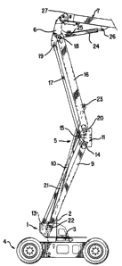
Referring to the drawings, and more particularly to
Figs. 1, 2 and 3, the low profile self propelled aerial
work platform of the present invention comprises a super-
structure support frame 1, having vertically extending
plates 2 upon which counterweights, not shown, are
adapted to be mounted; the support frame is mounted on a
turntable 3 carried by a vehicle chassis 4. An
articulated parallelogram boom assembly 5 is operatively
connected between the support frame 1 and a riser 6
connected to the proximate end portion of telescopic boom
assembly 7 having a work platform 8 mounted on the distal
end thereof.
The articulated parallelogram boom assembly 5
includes a lower boom assembly having pairs of parallel,

2 1 77344


laterally spaced compression and tension arms 9 and 10,
respectively, extending between the support frame 1 and
a floating frame 11, the arms being pivotally connected
to the support frame as at 12 and 13, and to the floating
frame as at 14 and 15. The articulated parallelogram
boom assembly 5 also includes an upper boom assembly
having pairs of parallel, laterally spaced compression
and tension arms 16 and 17, respectively, extending
between the riser 6 and the floating frame 11, the arms
16 and 17 being pivotally connected to the riser as at 18
and 19, and to the floating frame 11, as at 20 and 15,
which is the same pivot connection for tension arms 10 in
the lower boom assembly.
An extensible hydraulic cylinder 21, positioned on
the centerline of the machine, is pivotally connected as
at 22 to and between the lower compression arms 9, and as
at 23 to and between the upper compression arms 16,
whereby, when the cylinder 21 is retracted, the
parallelogram assembly 5 is in the folded position, as
shown in Fig. 1, and is in the elevated position, as
shown in Fig. 2, when the hydraulic cylinder 21 is
extended.
A boom lift cylinder 24 is similarly pivotally
connected along the centerline of the machine, above
cylinder 21, between the riser 6, as at 25, and the tele-
scopic boom assembly 7, as at 26. The remaining
components on the telescopic boom assembly 7 are
conventional and include a master hydraulic cylinder 27
for controlling a slave cylinder 28 on the distal end of
the telescopic boom assembly 7 for maintaining the work
platform 8 in a horizontal position during the raising
and lowering of the parallelogram assembly 5 and the
luffing of the telescopic boom assembly 7 with boom lift
cylinder 24. In the folded or retracted position of the
parallelogram assembly 5, cylinder 21 is nested between

21 77344


-the pairs of arms 9, 17 and 16, and boom lift cylinder 24
is nested between arms 16, above cylinder 21, and master
hydraulic cylinder 27, as well as the cylinder inside the
telescopic boom assembly 7 for extending and retracting
the same are,positioned above the other cylinders on the
centerline of the machine.
Figs. 7 and 8 illustrate the details of the common
pivot connection 15 between the tension arms 10 and 17 at
the floating frame 11 wherein it will be seen that a
transversely extPn~ing plate 29 is integral with the side
walls of the floating frame 11 and has a plurality of
spaced, short tubular members 30, 31, 32 integral with
the plate 29 and ext~n~ing outwardly therefrom. Each of
the tension arms 10 and 17 are provided with enlarged
portions lOa and 17a which extend into the respective
spaces between the tubular members 30, 31 and 32, and the
pivot bolt connection 15 extends transversely through the
side walls of the floating frame 11, the enlarged end
portions lOa and 17a of the tension arms 10 and 17, and
the tubular members 30, 31, 32.
As shown in Figs. 3 and 6, the opposite side plates
of riser 6 are spaced apart a smaller distance than the
support frame plates 1 to which the pairs of arms 9 and
10 are pivotally connected at 12 and 13, respectively.
This allows the lower end of riser 6, in the retracted
position of the parallelogram boom assembly 5 to extend
down between support frame plates 1, as shown
particularly in Figs. 4 and 6, so that pivot connection
19 of the pair of tension arms 17 to the riser 6 is
positioned in axial alignment with the pivot connections
13 of the pair of tension arms 10 to the support frame
plates 1. The pair of arms 17 are connected between the
side walls of riser 6 and are thus spaced apart a smaller
distance than the spacing between the pair of tension
arms 10, and thus lie between the pair of arms lO in the

21 77344


retracted position.
The pair of compression arms 16 are pivotally
connected at 18 on the outer sides of the side plates of
riser 6, as shown in Fig. 6, so that the pair of arms 16,
the pair of arms 10 and the pair of arms 9 are spaced
apart substantially the same distance to provide a very
stable parallelogram assembly, with only the pair of arms
17 being spaced apart a lesser distance than the others.
As will be seen in Figs. 7, 9 and 10, a synchroniz-
ation linkage 33 is provided for maintaining the verticalorientation of the floating frame 11 during the raising
and lowering of the articulated parallelogram boom
assembly 5. The linkage comprises a transversely
exten~ing tubular housing 34 ext~n~ing between and
integral with the inner walls of the compression arms 16,
through which the pivot connection bolt 20 extends.
Similarly, a transversely extending housing 35 extends
between and is integral with the inner walls of the
compression arms 9. A pair of spaced, parallel forwardly
extending ears 36 are integral with the housing 34, and
a pair of spaced, parallel, upwardly ext~n~ing ears 37
are integral with the housing 35. A link 38 extends
between the pairs of ears 36 and 37, and its opposite end
portions are positioned in the spaces therebetween and
pivotally connected thereto by pins 39 and 40. By this
construction and arrangement the link 38 extends
diagonally relative to the pivotal connections 14 and 20,
so that the link pivot connection 39 is on one side of
the compression arm 16 pivot connection 20, and the link
pivot connection 40 is on the other side of the
compression arm 9 pivot connection 14, whereby during the
actuation of the hydraulic cylinder 21 to pivot the
compression arms 9 and 16 relative to each other, the
link 38 will cause the floating frame 11 to remain in a
vertical orientation and synchronize the movement of the

21 77344
-

upper parallelogram assembly relative to the lower
parallelogram assembly.
To complete the structural description, the
transverse wall 29 is reinforced by a pair of spaced,
parallel reinforcing plates 39' extending between and
integral with the wall 29 and front wall of the floating
frame 11.
From the above description it will be readily
apparent to those skilled in the art that by providing
the tension arms 10 and 17 with a common pivot 15 on the
floating frame 11, the pairs of arms 10 and 17 inter-
digitate and lie in the same common horizontal plane when
the articulated parallelogram boom assembly 5 is lowered
to the folded position, whereby the low profile self
propelled aerial work platform can be maneuvered in
warehouses or manufacturing plants having relatively low
doorways, such as, six feet, seven inches. In the
lowered folded position the parallelogram boom assembly
5 lies in three closely adjacent horizontal planes, with
the spaced arms 9 in the lowermost horizontal plane,
parallel to the top of the superstructure horizontal
plate on the turntable, the inter-digitated pairs of
spaced arms 10 and 17 being in the center horizontal
plane, and the spaced arms 16 being in the upper
horizontal plane closely adjacent the center horizontal
plane. The telescopic boom assembly 7 pivots down on top
of the parallelogram boom assembly 5 in substantially a
fourth planè above the upper horizontal plane, whereby
the proximate end of the telescopic boom assembly
adjacent its pivot connection with riser 6, is the
highest point of the machine in the folded travel
position, and is approximately six feet, six inches in
height above the ground plane. The machine is
approximately eighteen feet, eight inches in overall
length, and five feet, nine inches in width which allows

21 77344

it to travel through standard width double doors having
a six foot width. In the raised position of Fig. 2, with
the telescopic boom assembly extended and elevated, the
floor of the work platform 8 is approximately forty feet
above the ground plane.
The terms and expressions which have been employed
herein are used as terms of description and not of
limitation, and there is no intention, in the use of such
terms and expressions, of excluding any equivalents of
the features shown and described or portions thereof, but
it is recognized that various modifications are possible
within the scope of the invention claimed.

Representative Drawing
A single figure which represents the drawing illustrating the invention.
Administrative Status

For a clearer understanding of the status of the application/patent presented on this page, the site Disclaimer , as well as the definitions for Patent , Administrative Status , Maintenance Fee  and Payment History  should be consulted.

Administrative Status

Title Date
Forecasted Issue Date 2003-08-05
(22) Filed 1996-05-24
(41) Open to Public Inspection 1996-12-01
Examination Requested 2001-05-04
(45) Issued 2003-08-05
Expired 2016-05-24

Abandonment History

There is no abandonment history.

Payment History

Fee Type Anniversary Year Due Date Amount Paid Paid Date
Application Fee $0.00 1996-05-24
Registration of a document - section 124 $0.00 1996-08-22
Maintenance Fee - Application - New Act 2 1998-05-25 $100.00 1998-05-01
Registration of a document - section 124 $50.00 1999-01-21
Maintenance Fee - Application - New Act 3 1999-05-25 $100.00 1999-05-11
Maintenance Fee - Application - New Act 4 2000-05-24 $100.00 2000-05-04
Request for Examination $400.00 2001-05-04
Maintenance Fee - Application - New Act 5 2001-05-24 $150.00 2001-05-04
Maintenance Fee - Application - New Act 6 2002-05-24 $150.00 2002-05-21
Final Fee $300.00 2003-03-31
Maintenance Fee - Application - New Act 7 2003-05-26 $150.00 2003-05-15
Maintenance Fee - Patent - New Act 8 2004-05-25 $200.00 2004-05-20
Registration of a document - section 124 $100.00 2005-04-13
Maintenance Fee - Patent - New Act 9 2005-05-24 $200.00 2005-04-19
Maintenance Fee - Patent - New Act 10 2006-05-24 $250.00 2006-04-24
Maintenance Fee - Patent - New Act 11 2007-05-24 $250.00 2007-04-18
Maintenance Fee - Patent - New Act 12 2008-05-26 $250.00 2008-04-22
Maintenance Fee - Patent - New Act 13 2009-05-25 $250.00 2009-04-16
Maintenance Fee - Patent - New Act 14 2010-05-24 $250.00 2010-04-16
Maintenance Fee - Patent - New Act 15 2011-05-24 $450.00 2011-04-18
Maintenance Fee - Patent - New Act 16 2012-05-24 $450.00 2012-04-16
Maintenance Fee - Patent - New Act 17 2013-05-24 $450.00 2013-04-15
Maintenance Fee - Patent - New Act 18 2014-05-26 $450.00 2014-04-15
Maintenance Fee - Patent - New Act 19 2015-05-25 $450.00 2015-04-13
Owners on Record

Note: Records showing the ownership history in alphabetical order.

Current Owners on Record
JLG INDUSTRIES, INC.
Past Owners on Record
GOODRICH, MICHAEL F.
GROVE U.S. LLC
KIDDE INDUSTRIES, INC.
Past Owners that do not appear in the "Owners on Record" listing will appear in other documentation within the application.
Documents

To view selected files, please enter reCAPTCHA code :


To view images, click a link in the Document Description column. To download the documents, select one or more checkboxes in the first column and then click the "Download Selected in PDF format (Zip Archive)" or the "Download Selected as Single PDF" button.

List of published and non-published patent-specific documents on the CPD .

If you have any difficulty accessing content, you can call the Client Service Centre at 1-866-997-1936 or send them an e-mail at CIPO Client Service Centre.


Document
Description 
Date
(yyyy-mm-dd) 
Number of pages   Size of Image (KB) 
Representative Drawing 2003-02-05 1 8
Cover Page 2003-07-03 2 50
Representative Drawing 1998-05-07 1 21
Cover Page 1996-09-03 1 18
Abstract 1996-09-03 1 35
Description 1996-09-03 8 360
Claims 1996-09-03 4 185
Drawings 1996-09-03 9 228
Prosecution-Amendment 2002-11-27 2 51
Correspondence 2003-03-31 1 48
Fees 2003-05-15 1 42
Fees 2002-05-21 1 54
Fees 1998-05-01 1 55
Assignment 1996-05-24 21 843
Fees 1999-05-11 1 58
Prosecution-Amendment 2001-05-04 1 82
Fees 2001-05-04 1 54
Fees 2000-05-04 1 57
Fees 2004-05-20 1 44
Assignment 2005-04-13 2 70
Assignment 2005-09-13 11 408