Note: Descriptions are shown in the official language in which they were submitted.
; r
(/~17 JJrn-Jso
f.+ryJ~ ~ ~(t~~ il ~1fi~4-tsk~
IM 94-36. 94-38
PiwPec-T\9654.LY
CATHETER ARRANGEdlENT WITH INTERLOCKING
1 SE~UENCED GUARDING MEMBERS FOR PROTECTING CANNULA
BACKGROUND OF THE INVSNTION
1. Field of the Invention
The present invention relates, in general, to
intravenous catheter insertion devices, and in
particular pertains to a catheter needle tip protector
and a safety mechanism which provides fail-safe
protection for clinical personnel against the
possibility of accidental punctures by a used IV
cannular needle through automatic catheter needle tip
protecting structure operative upon withdrawal of the
cannular from a venipuncture the body of a patient.
In particular, pursuant to specific aspects of
the invention, there is provided a catheter insertion
device incorporating interlocking sequenced guarding
members which are capable of being utilized in a
considerable variety and types of catheter insertion
devices. in essence, an important consideration which
must be given to the aspect that there is a present
safeguard in essentially a "fail-safe" arrangement,
whereby the used cannula is fully retracted into its
protective structure or housing prior to disengagement
thereof from a catheter hub. Hereby, it has been noted
that, upon occasion, needle stick of users of the device
may be encountered in that the needle tip of the used
cannula may still protrude to some extent, and
resultingly pose a danger or hazard to clinical
personnel or physicians using the catheter insertion
device during separation of the cannula assembly from
the catheter and its attached catheter hub. In numerous
- -
i
2178249
-2-
1 constructions and designs of catheter insertion devices,
for example, such as the currently employed so-called
Luer lock versions or sideport catheters, various
techniques and structures are employed for separating
retracted used cannulas and their associated housings
and protective structures from the respective catheter
and catheter hub portion, the former of which is still
inserted in the venipuncture formed in the body of a
patient and which is adapted to be.connected to various
other sources of parenteral fluids, blood, medications
and the like during intravenous fluid supplying
procedures, as is well known in the medical technology.
An important aspect of the invention resides
in being able to ensure that the structure of the
housing and telescopable sequencing guards for the used
cannula or hollow needle which is being retracted will
impart a clear indication as to the efficacy of full
retraction of the cannula, thereby ensuring not only
visual but also audible assurance of such protective
procedures having been implemented during the catheter
and cannula separation process, and prior to the
effecting of the release of the housing or structure
protectively containing the used cannula from the
catheter hub.
Pursuant to a particular aspect of the
invention, which may be applicable to various types of
catheter insertion devices as described hereinbelow,
there is provided a structure comprising interlocking
sequenced guarding members whereby in a plurality of
telescoping steps, the cannula, comprising the hollow
needle, may be retracted into the guarding members in a
t =
~ 2178249
-3-
1 step-by-step relationship as the guarding members are
telescopingly extended relative to each other so as to
ultimately provide a multiple locking system generating
sequentially generated audible sounds or "clicks"
informing clinical personnel operating the catheter
device that the cannula has, in fact, been fully
retracted and protectively locked in place, and
consequently will no longer pose any physical danger or
hazard to the user or clinical personnel, thereby
enabling the completing of safe separation of the needle
or cannula-housing structure from the catheter hub.
The utilization of clinical apparatus in which
pointed hollow needles or cannulas are employed in order
to puncture the skin of a patient, and especially
catheters utilizing such needles to effectuate
venipunctures, is well known in the medical art and is
widely practiced by physicians and clinical personnel
for the purpose of injecting fluids and drugs directly
into the bloodstream of patients. Additionally, during
surgical operations or procedures it may be frequently
required that whole blood transfusions and parenteral
fluids be administered to a patient undergoing such
surgical procedures. Basically, as is well known and
has been employed for a considerable length of time, the
introduction of such fluids into the cardiovascular
systems of patients has necessitated the forming of a
venipuncture utilizing a hollow rigid needle having a
proximal attachment site for a fluid connection which is
adapted to interconnect the needle with a source of
intravenously administered fluids.
i 2178249
-4-
1 The foregoing method of administering fluids
to patients through venipunctures has been subject to
some rather serious problems in the administration of
fluids to patients in this medical technology. Thus, a
primary concern which had to be addressed resided in the
inherent rigidity of the needle, the latter of which is
normally generally constituted of surgical-quality
steel, and while inserted into the vein of a patient,
necessitated the needle to be maintained for reasons of
safety in a fixed position at the general site of the
venipuncture throughout the duration of fluid
administration or transfusion, whereby such a procedure
could conceivably consume a considerable length of time.
In addition to the foregoing, at times it has been
necessary to periodically draw blood samples and/or
successively administer intravenous fluids to a patient,
thus requiring the patient to be subjected to a series
or plurality of venipunctures, each administered at a
specific time and at different sites on the body,
resulting in a relatively traumatic experience to the
patient in view of such repeated and somewhat painful
and unpleasant venipunctures.
In order to ameliorate or possibly even
eliminate the foregoing problems, in the medical
technology it has been more recently the practice to
introduce a flexible tubular catheter of a low-friction
material, such as a silastic or Teflon into the vein of
a patient and to permit the catheter tube to remain in
such a position over lengthier periods of time for
purposes of; for example, periodically administering
fluids, including parenteral fluids, blood/plasma
2178249
1 transfusions, medications in liquid form and also for
the collection of blood samples and the like. In this
manner, the previously encountered trauma,
extravasation, and infiltration caused by repeated
venipunctures have been largely avoided, and the danger
and discomfort to a patient of leavinga rigid needle in
the body for a prolonged period of time has been
generally overcome. Thus, in order to position the
distal end of such a flexible catheter tube within the
body cavity of a patient, such as a vascular cavity or
vein, there is normally employed a cannula or hollow
sharp-tipped needle for the purpose of forming the
venipuncture. Thereafter, the flexible catheter tube,
which is telescopically and slidably coaxially mounted
on the outer circumference of the cannula or hollow
needle so as to extend sleeve-like thereabout is
advanced along the length of the needle into the vein
subsequent to the needle having formed the venipuncture.
Thereafter, the needle is adapted to be withdrawn from
the interior of the catheter tube, while permitting the
latter to remain within the body of the patient at the
site of the venipuncture, and the needle is suitably
discarded.
Inasmuch as the needle which has been
previously positioned in the body of the patient upon
forming the venipuncture may have been exposed to
infectious agents; for instance, such as a patient
infected with the Acquired Immune Deficiency Syndrome
(AIDS) which is frequently or practically always
ultimately fatal in nature, or other dangerous
infectious conditions such as hepatitis, there is
J
~ 2178249
-b-
1 present the danger or hazard that the clinical personnel
may inadvertently or accidentally jab or stick
themselves with the used needle after withdrawal from
the body of the patient, with the possibility of
infection or even death resulting therefrom.
2. Discussion of the Prior Art
Although extendable or telescoping elements
for protecting used cannulas of catheter insertion
devices are currently known in the art, none of these
provide for the use of interlocking sequenced
telescoping guarding members for the "fail-safe"
retraction and protection of the cannulas.
Thus, U.S. Patent No. 4,950,252 to Luther
et al. discloses a cannula guard and housing structure
which are mutually relatively axially extendable for
receiving therein a used cannula in a protective
environment.
McDonald U.S. Patent No. 4,944,725 addresses
the problem in disclosing an intravenous catheter which
incorporates a structure for protecting a clinician or
physician from accidental puncture which may result in
the transfer of dangerous infections from the patient.
The catheter is introduced into the patient's body with
the aid of a needle of hollow or cannula construction
which is thereafter withdrawn from the patient's body
into a protective housing in the absence of exposing the
needle during any intermediate stage of the withdrawing
process. The housing is then latched in place
subsequent to needle withdrawal, and for unlocking a
catheter hub in place subsequent to the time, and
2178249
-7-
1 affecting withdrawal and locking in one continuous
motion.
Another publication which is applicable to
providing for the protection of the point of a needle
subsequent or upon removal thereof from the body of a
patient is disclosed in Dombrowski et al. U.S. Patent
No. 4,790,828, wherein a nose portion or cap is tethered
to a housing by means of a collapsible tethering
structure encompassing the needle such that the needle
will be retracted into a sheath-like expanding
arrangement which will securely prevent potential injury
to clinical personnel caused by being jabbed by an
exposed used point of a needle.
SUMMARY OF THE INVENTION
Accordingly, in order to provide an improved
structure in the provision of a protecting arrangement
for a used cannula, and especially a safety mechanism
which will ensure a practically "fail-safe" operation,
the present invention contemplates the provision of
telescopically sequentially movable guarding members in
the form of sleeves or housing whereby locking devices
provide for the locked extension of the cannula prior to
its use in guiding a catheter into the vein of a
patient, and thereafter, when it is desired to retract
the cannula, while the components remain in a locked
condition, there is effected a first extension step
whereby an outer housing sleeve passes beyond a detent
in one of the guarding members, thereafter in a second
step permitting unlocking between the inner guarding
members, and enabling the housing sleeve to be further
2178249
-~-
1 extended rearwardly while a second two-way lock is in an
unlocked position; and in a further step, while the
initial locking structure remains unlocked and the
second remaining locking structure is also in an
unlocked condition, to facilitate further complete
extension between the sequenced interlocking guarding
members in which the forward guarding member in which
locked into the back guarding member, and the back
guarding member is locked into the sleeve-like housing
so as to fully encompass the cannula.
Accordingly, it is an object of the present
invention to provide a catheter insertion device
providing for a "fail-safe" retraction of a used cannula
into a sequenced telescopable guarding arrangement or
structure.
A more specific object of the invention is to
provide a guarding structure into which a used cannula
may be retracted prior to separation of the structure
from a catheter, and in which, through a plurality of
releasably locked interconnecting sequenced guarding
members, this will ensure the complete and safe
retraction of the cannula into a protective environment.
Another object of the present invention
resides in the provision of a catheter insertion device
of the type described in which the interlocking
sequenced guarding members enabling the complete
retraction of a used cannula will effectuate the latter
function through the sequential disengagement and/or
engagement of a plurality of axially spaced locking
devices, each such locking device providing for an
audible indication as to the efficacy of the locking
2178 ?49
-9-
1 action so as to apprise the user of the complete
retraction of the cannula having taken place.
BRIEF DBSCRIPTION OF THE DRAWINGS
Reference may now be had to the following
detailed description of exemplary embodiments of the
invention, taken in conjunction with the accompanying
drawings; in which:
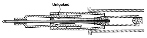
Figure 1 illustrates a perspective view of a
first embodiment of a catheter insertion device, shown
with the cannula in the fully extended operative
position thereof;
Figure 2 illustrates a view similar to Figure
1 illustrating the cannula in the fully retracted and
guarded position within the device;
Figure 3 illustrates a side view of a housing
member of the cannula assembly;
Figure 4 illustrates a front end view of the
housing member of Figure 3;
Figures 5, 6 and 7 illustrate, respectively,
top, side and front end views of a forward guarding
member.for the cannula;
Figures 8, 9 and 10 illustrate, respectively,
top plan, side and front end views of a back guarding
member adapted to be operatively and telescopingly
associated with the housing member and the front
guarding member of the cannula assembly structure;
Figures lla through lle illustrate,
respectively, various operative positions of the
interlocking sequenced telescopable guarding members of
~ 2178249
-10-
1 Figures 3 through 10, -caken along Line 11-11 in Figure
4;
Figures 12a through 12e illustrate views
similar to those of Figures lla through lle taken along
Line 12-12 in Figure 4;
Figure 13 illustrates a perspective view of a
further embodiment of a catheter sideport insertion
device, shown with the cannula in the fully extended
operative position; and
Figure 14 illustrates, in an exploded
perspective view, the catheter insertion device of
Figure 13 with the cannula in its fully retracted
position and the catheter sideport portion having been
separated therefrom.
DETAILED DESCRIPTION OF PREFBRRSD EMBODTPnM'rS
Referring now in detail to Figure 1 of the
drawings, there is illustrated, generally
diagrammatically, a perspective view of a catheter
insertion device 10 wherein the cannula 12 thereof is
locked in its fully extended operative position and in
which a push-tab 14 and nose guard 16 are arranged on a
forward cannula guarding member 18 which is adapted to
be slid or extended, as described hereinbelow, from a
housing 20, in this instance containing a blood chamber
22.
As illustrated in Figure 1, the catheter
insertion device 10 also includes the nose guard 16
through which the cannula 12 extends in a slidable
manner, and wherein a second or back guarding member 24
is arranged telescopically within the forward guarding
CA 02178249 2006-11-23
-11-
1 member 18 and is also adapted to be posi.tioned,within
the housing 20. As represented, the housing 20 includes
finger-engaging surfaces 26 on opposite sides thereof
(only one shown) which may be ribbed in nature to
prevent the fingers of a user or clinical personnel from
slipping off during use and also for holding the device
in a good gripped position during insertion of the
cannula 12 or hollow needle tip thereof into the body of
a patient so as to effect a venipuncture. The nose
guard is adapted to mate with a catheter hub 30 which
may be in the nature of an element containing a Luer
lock lug structure, and which has a catheter tube
closely and slidably extending over the outer surface of
the cannula 12, the catheter tube being flexible in
nature and constituted of a low friction plastic
material, such as Teflon or the like, as is well known
in the medical technology.
As illustrated in Figure 2 of the drawings,
upon the catheter having been extended over the cannula
12 into the venipuncture formed in the patient's body,
the cannula is then withdrawn to a fully guarded
position within the cannula assembly, and there also
enabling separation therefrom of the catheter hub 30 and
the catheter tube extending into the vein of the patient
at the puncture site. This separation may be effected
in numerous ways depending upon the type of catheter
insertion device employed and; for example, in various
cases may be as disclosed in the embodiments of catheter
insertion devices disclosed in U.S. Patent No. 5,713,876.
CA 02178249 2006-11-23
-12-
1 In that instance, as disclosed in U.S. Patent No. 5,713,876,
various mechanisms are described for the purpose of
releasing and separating the cannula assembly containing
the cannula retracted therein in a guardedly protective
position from its connection to a catheter hub and
attendant catheter, whereby the catheter hub may
incorporate a component of a Luer lock or the like.
This separation between the components may be
implemented by means of a lever and clip element which
is pivotable or tiltable in various orientations as
described therein, or through the actuation of a
suitable push-tab and guard element.
As disclosed herein, having reference to
Figures 3 and 4 of the drawings, the housing 20 is
essentially an elongated hollow rectangular member
having a front wall structure 30 and an upper
longitudinally extending wall opening 32 through which
there can be viewed a blood chamber 34 located therein,
the latter of which is in communication with the lumen
of the cannula 12, and wherein a slidable insert 36 of
generally cylindrical or tubular configuration
incorporates sealing elements 38, 40 at both ends
thereof so as to close in a quantity of blood from the
body of the patient.
The.forward or front guarding member 18 is of
a generally bifurcated structure of having two generally
flat parallel spaced sidewalls 42, 44 and wherein an
upper push-tab structure 46 and forward tab or plate 48
are integrally formed therewith, and which extends into
2178?49
-13-
1 a nose guard 50, as shown in Figures 5 to 7 of the
drawings. Various configurations of this particular
nose guard member and cannula tip protector may be
utilized, and other designs without the nose and cannula
tip protector may also be contemplated for other types
of catheter insertion devices or Luer lock-catheter
structures.
The rear or back guarding member 24 is adapted
to be slidably disposed in telescopable relationship
over the forward guarding member 18 and includes a
longitudinal passageway into which the bifurcated
sidewall members 42, 44 can slidably enter so as to
allow for telescoping relatively slidable movement
between the guarding members. These members 18, 24 are
insertable into the longitudinal extent of the housing
20, as shown in Figures 1 and 2 of the drawings, and the
operative latching function of which is clearly
described with reference to Figures lla through lle and
Figures 12a through 12e of the drawings.
With respect to the function of the
interlocking sequenced or telescopingly movable guarding
members 18 and 24, reference may now be had to Figure 1
of the drawings, whereby Figures lla and 12a illustrate
sectional views of the components in the position
whereby the cannula 12 is locked in its fully extended
operative condition adapted to be inserted into the vein
of a patient. Hereby, the proximate end of the catheter
extends through seal 38 so as to be in communication
with a cylindrical chamber 54 formed by the cylindrical
insert-36, and the opposite end of which is closed by
the further sealing element 40 so as to be able to
2178249
-14-
1 receive and store blood, if necessary, from the vein of
a patient.
The housing 20 is illustrated as having the
rear or back guarding member 24 entirely fully
positioned therein, and with the front or forward
guarding member 18 being essentially completely
positioned within the back guarding member 24. The
forward guarding member 18 has the nose piece or guard
50 adapted to extend into a catheter hub (not shown),
and which includes a passageway 58 through which the
cannula 12 may readily pass in slidable operation. A
seal 60 may be provided so as to encompass the extent of
the cannula 12 at that location.
In the position shown in Figures lla and 12a,
a pair of lugs 62, 64 protruding from the outer diameter
of the forward guarding member 18 each engage into
respective detents 66 formed in the periphery of the
back guarding member 24, and which are positioned in
alignment therewith so as to prevent relative axial and
rotational motion therebetween.
At that point in time, the rear portion of the
forward guarding member 18 has its inwardly extending
lugs 70 on the bifurcated arms unlatched relative to the
remaining cannula components.
when effecting the initial retraction of the
used cannula 12 upon withdrawal from the vein of the
patient into the cannula assembly, as shown in Figures
llb and 12b of the drawings, the forward and back
guarding members 18, 24 are still in a mutually locked
position, while the housing 20 is pulled backwards by
being manually engaged at its gripping surfaces so as to
-
. ~
2178249
-15-
1 draw therewith the cannula 12 and the chamber at the
distal end thereof which communicates with the cannula
12.
In a third extension step, upon further
movement of the housing member and the cannula, the
outwardly extending protrusions or lugs 62, 64 on the
forward guarding member 18 disengage from the detents 66
in the back guarding member, since the bifurcated
sidewalls 42, 42 are deflected outwardly at that
location, being essentially elastically resilient in
nature. This releases the forward guarding member 18
from the back guarding member 24 at the same time, which
causes the back guarding member 24 to be locked in the
housing 20, with the aid of the locks 74, 79 at the rear
of the guarding member.
In a fourth step, the housing 20 is still
further retracted and whereby there is an unlocked
condition present between the two guarding members 18,
24 enabling these to be telescopically extended apart.
Upon the final condition of telescopic
extension having been reached by the components 18, 24
and 20, as shown in Figures lle and 12e of the drawings,
the protuberances or lugs 62, 64 on the forward guarding
member 18 are in an exposed condition, whereas the two-
way lock 74, 76 snaps into detents 78 in an internal
guide rib 80 formed in the housing 20, and concurrently
the back guiding member 24 is latched to the housing 20
by another two-way lock 84. In that position of the
members 18, 24 and housing 20, as illustrated in Figures
lle and 12e, the cannula 12 is entirely retracted within
the cannula assembly consisting essentially of the
~
CA 02178249 2006-11-23
-16-
1 forward guarding member 18, the back guarding member 24
and the housing 20, which are telescoped in the extended
position shown in Figures 2, lie and 12e of the
drawings, whereupon it is then possible to effectuate
the release of the catheter hub from the nose guard end
of the cannula assembly, as mentioned hereinabove and as
disclosed in U.S. Patent No. 5,713,876.
Referring to Figures 13 and 14 of the
drawings, this illustrates a modified catheter insertion
device 90, which is primarily a sideport catheter,
wherein the catheter hub 92 includes an openable
sideport 94 for adding further fluids or medications to
the parenteral fluid being conducted through the
catheter into the vein of a patient.
In this instance, there is provided a push-tab
96 for Luer lock release, which is adapted to disengage
the cannula structure 98 from the catheter hub 92, the
latter of which includes Luer lock lugs 100 formed
thereon. For the remainder, the structure of the
housing and the telescopably extendable forward and back
guarding members are essentially analogous or similar in
structure and function with those described with regard
to the embodiment of the catheter insertion device shown
in Figure 1 of the drawings. Hereby, with respect to
the embodiment of Figure 13 relative to the sideport
catheter construction, this shows the catheter hub
having been separated through actuation of the push-tab
96 for the Luer lock so as to disengage the lugs 100 on
the catheter hub 92 and to permit the entire cannula
~ 2178249
-~ ~-
1 assembly with the therein retracted and guarded cannula
to be discarded.
The foregoing provides for a completely
dependable and essentially "fail-safe" retraction of a
used cannula or hollow needle into a guarding structure
so as to prevent any hazard to clinical personnel or any
users by jabbing or sticking themselves with the tip of
the needle.
The telescopable forward and back guarding
members 18, 24 in conjunction with the housing 20 may be
utilized for numerous types of catheter injection
devices, whereby the devices may be separated from a
catheter hub or Luer lock by either actuating a lever
and clip construction, or in any other suitable manner
pursuant to the technology.
The components may be essentially formed of
simple molded parts and from inexpensive plastics, as is
well known and currently employed in the medical
technology.
While there has been shown and described what
are considered to be preferred embodiments of the
invention, it will, of course, be understood that
various modifications and changes in form or detail
could readily be made without departing from the spirit
of the invention. It is, therefore, intended that the
invention be not limited to the exact form and detail
herein shown and described, nor to anything less than
the whole of the invention herein disclosed as
hereinafter claimed.