Note: Descriptions are shown in the official language in which they were submitted.
~i80041
TWO WIRE PIR OCCUPANCY SENSOR UTILIZING
A RECHARGEABLE ENERGY STORAGE DEVICE
Inventor: Albert Zaretsky
BACKGROUND OF THE INVENTION
A well known problem with conventional Passive Infra Red (PIR)
occupancy circuits that use a relay output in a two wire system (i.e., no
neutral) is
that when the relay contact is closed, there is no power available to drive
the
control circuitry since the relay contacts short circuit the control
circuitry. This
problem is not exclusive to PIR occupancy circuits. In fact, any generic two
wire
electrical control device that switches power across a load when energized may
display a similar problem, i.e., when the switched contact is in a low
impedance
state (the relay contacts are closed), the voltage across the device drops
from a
level approximate to that of the AC line voltage to almost zero. Thus, during
the
time the control device is on (energized), no power is available to drive the
switching control circuitry.
One solution known in the art utilizes a technique whereby a small amount
of current is purposely leaked to ground to drive control circuitry when power
is
switched across the load. The switching control circuitry, if designed so as
to
require a small amount of current to keep it operational (compared to the load
circuitry), can derive the power it needs for operation from this ground
leakage
current. Underwriters Laboratory (UL) allows electrical devices 0.5 ma of
leakage
current wherefore such ground leakage current operation can be arranged.
However, the 0.5 ma leakage current limitation makes designing using this
technique difficult to implement.
~1800~1
For example, U.S. Patent No. 4,713,598 to Smith discloses a power supply
circuit for generating power from a switched AC source. The circuit includes a
current transformer arranged in series with a controlled main conduction path
(contact) of a relay switch disposed in the AC source/load main line. A series
combination of a capacitor and a secondary winding of the transformer shunt
the
primary winding/relay contact series combination. When the relay switch is
conductive, a comparatively small AC voltage appears across a secondary of the
transformer which is rectified with a rectifying diode electrically connected
to
power an amplifier. A capacitor connected in shunt with the amplifier filters
the
DC generated by the diode. The amplifier is driven by a detection circuit
(e.g., a
passive infrared detector) which drives the relay switch. When the contact is
in a
non-conducting state (i.e., a high impedance state), no current flows in the
transformer's primary. However, because little voltage is dropped across the
load,
almost the full potential of the AC source appears across the blocking
capacitor/transformer secondary series combination. This open circuit
potential is
used to power the circuitry when the relay is non-conducting, i.e., ground
leakage
current.
U.S. Patent No. 4,336,464 to Weber discloses a two-terminal timed electric
switch for series connection with one side of a power-carrying AC circuit. An
AC
line terminal is electrically connected in series through a primary of a
current
transformer and a contact of a relay switch to a load. The load's other
terminal is
connected to the AC neutral. While the load is energized, the transformer's
secondary provides power to a timer circuit. The circuit is energized when a
momentary action start ("on") switch is temporarily closed (pressed) whereby
the
power is generated in the secondary for closing the relay contact. This
momentary
contact switch must be actuated before the Weber circuitry can be actuated.
For
2
~1800~1
example, were the timer circuit to be a PIR occupancy circuit, operation of
the PIR
circuitry would first require momentary closure of the momentary switch.
It would be beneficial, therefore, to realize a device for use in two-wire
detector or sensor circuit which utilizes an energy source for operating the
sensor
independent of load activation or ground leakage current. The energy source
could
be independent from current operation, or dependent thereon, e.g., a charge
storage
device. It would also be beneficial to have a device for use in a two-wire
sensor or
detector circuit wherein a current transformer is utilized to indirectly
supply the
sensor or charge storage device during a time at which said load is powered by
said AC source thereby minimizing the storage requirements of the charge
storage
device.
OBJECTS AND SUMMARY OF THE INVENTION
Accordingly, it is an object of the present invention to provide a two wire
sensor, such as a passive infrared occupancy sensor, with means for storing
electrical power to drive internal sensor control circuitry when source
electrical
power which drives both the sensor and the load is switched across the load.
It is another object of the present invention to provide a two-wire sensor
with means for storing electrical power for driving sensor control circuitry
when
source electrical power which drives both the sensor and the load is switched
across the load, the stored power derived from the source during that time in
which
the source drives the load.
In a preferred embodiment, the present invention discloses a two wire
sensor which includes switching means setable to one of a high (e.g., open
circuit)
and a low impedance state (i.e., short circuit) in response to a switching
signal for
disconnecting/connecting a source of AC power to/from an electrical load. The
switching means is interposed within a main conduction path providing power
X180041
between the AC source and the load. The switching means is connected between a
first leg of the AC source and a first terminal of the electrical load. The
second
terminal of the electrical load is connected to a second leg of the AC source.
An
energy storage means for storing electrical charge is included which is
electrically
coupled to the first leg of the AC source and to the first terminal of the
electrical
load. A charge control means is electrically disposed between the switching
means and the energy storage means for regulating the voltage across the
energy
storage means and therefore the current flowing therein. Circuitry for
controlling
the switching means is coupled across the energy storage means and responds to
detection (or sensing) of the monitored condition by generating the switching.
signal. The switching signal causes the load to be switched into or out of the
powered circuit. The charge stored in the energy storage means drives the
switching means.
BRIEF DESCRIPTION OF THE DRAWINGS
Fig. 1 is a functional block diagram of an embodiment of the invention
showing functional blocks and their interconnection; and
Fig. 2 is a functional block diagram of the preferred embodiment of the
invention shown functional blocks and their interconnection.
DETAILED DESCRIPTION OF THE INVENTION
Shown in Fig. 1 is one embodiment of a two-wire sensor circuit 10 of the
present invention (hereinafter referred to simply as the "circuit"). The
circuit 10
includes a first terminal for electrical connection to a first leg of an AC
power
source (AC HOT), and a second terminal for electrical connection to a first
end of
an electrical load 22. A second end of the load 22 is electrically connectable
to a
4
second leg of the AC source (AC NEUTRAL). A switching device 18, e.g., a
relay switch, is electrically connected between the first and second terminals
of the
circuit 10. The state of the switching device therefore is defined by circuit
operation to control power supplied to the load. The device may be set to
either of
two states, conducting or non-conducting, referred to interchangeably herein
as
"on" or "ofF' and "low impedance" or "high impedance" states, corresponding to
closed or open contact states of a relay switch. Switching device 18 is a
conventional latching type switch, thus consuming pulse power only during
switching periods. and consuming no power at all during other times.
A sensor circuit 16, e.g., a PIR control circuit, is electrically coupled to
switching means 18, i.e., coupled between the first leg of the AC source and
the
first end of load 22. The sensor circuit identifies a state of a condition
being
monitored and defines a state of the switching signal in accordance thereto.
The
sensor is preferably a passive infrared (PIR) control sensor for providing an
occupancy sensing function. The sensor comprises conventional circuitry well
known to those skilled in the art. The state of the switching means is defined
by
the sensor in accordance with an amount of infrared energy detected from an
object.
When the contact in switching means 18 is defined by~the sensor as open,
(i.e., a non-conductive state), substantially no power is delivered to the
load. A
majority of the AC source voltage appears across the circuit 10 while the
switching
means 18 is non-conductive because it comprises a relatively high impedance
relative to the load 22. Current is therefore provided both to an energy
storage
device 14 and the sensor circuit 16 through a charge control device 12. Charge
control device 12 is electrically disposed between the switching means and the
parallel combination of an energy storage device 14 and controller 16.
21~U041
While the switching means 18 of circuit 10 is in a conductive state, i:e., the
contact is closed, substantially all power is delivered to the load. Power
required
to drive the PIR control (sensor) circuit 16 during this time is provided via
energy
storage device 14, e.g., to de-energize the load. In addition to providing
current to
power the sensor (PIR control) circuit 16, the charge control circuit 12
comprises
conventional circuitry, well known to those skilled in the art, to limit,
filter and
control the voltage across the energy storage device 14 and current fed to it.
The
energy storage device 14 may consist of a conventional rechargeable battery
such
as nickel cadmium (NiCd), nickel metal hydride (NiMH), lithium or alkaline.
Alternatively, a double layer capacitor may be used: Suitable capacitors are ,
Maxcap double layer capacitors manufactured by Cesiwid, Inc. of Niagara Falls,
New York, or Supercap electric double layer capacitors, manufactured by NEC
Corporation of America. These double layer capacitors typically have
capacities
on the order of a few farads.
A circuit 10 of this invention which uses a rechargeable battery or a
capacitor having a value on the order of a few farads is practical when taken
in
light of the following example. Typically, circuit 10 is used for occupancy
sensing
whereby sensor control circuitry 16 embodies a PIR control circuit and
switching
means 18 embodies a latch relay. PIR control circuits utilizing latch relays
consume approximately 0.25 to 1 ma. Lithium coin battery cells, typically,
have
capacities of 50 to 500 ma-hrs (milliamp hours). A 200 ma-hr lithium battery
cell,
therefore, could maintain power to a 1 ma PIR control circuit for greater than
one
week while the PIR detector is subject to constant movement.
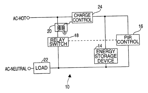
For indeterminate time periods in which the electrical load 22 must remain
energized, a second embodiment of this invention is described with reference
to
Fig. 2. The figure shows a circuit 10' similar to circuit 10 described above,
but
includes a conventional current transformer 20 for charging the energy storage
6
2180041
device 14 when the load is active, i:e., when the switching means is
conductive. It
also includes a modified charge control circuit 24 to handle the additional
source
of voltage (i.e., the current transformer 20) other than the AC power source
directly. Modified charge control circuit 24 accepts as inputs both the AC
power
source directly (i.e., AC HOT) and a first end of the secondary of the current
transformer 20, a second end of which is connected to control circuit DC
ground.
The primary winding of the current transformer 20 is connected between
the AC-HOT terminal of the AC power source and switching means (i.e., the
relay
switch) 18. While PIR control circuit 16 defines the state of the switching
means
(via the switching signal) to prevent a flow of power to the load, i.e., a
relay
contact of switching means 18 is open, no current flows through the primary
winding of the current transformer 20. Accordingly, the PIR control circuit 16
is
powered through the charge control circuit 24 from the AC power source. When
the circuit 10 defines an operational state in which the load is energized,
i.e., the
relay contact 18 is closed, the secondary of current transformer 20 provides
an
induced voltage signal via charge control circuit 24 to charge energy storage
device 14. The charge control circuit 24 comprises conventional circuitry,
well
known to those skilled in the art, to limit, filter and control the voltage
across the
energy storage device 14 and the current flowing through it. The charge
control
circuit 24 differs from charge control circuit 12 shown of Fig. 1 in that it
receives
both the AC power source directly and power output from the secondary of the
current transformer 20.
The embodiments of the invention disclosed in the present specification,
drawings and claims are presented merely as examples of the invention. Other
embodiments, forms, or modifications thereof will readily suggest themselves
and
are contemplated as coming within the scope of the present invention, which is
defined by the following claims.
7