Note: Descriptions are shown in the official language in which they were submitted.
t WO 95/29658 PCT/UB95105384
-1-
FOOT EGRESS CIi~AIR BEn
Field Of the Tnvantinn
This invention relates to a hospital bed that is
convertible to a chair. The structure of the present
invention is primarily useful for facilitating getting a
patient from a supine position on the bed to a standing
and/or walking position or into a wheelchair or other
ambulatory assisting device.
Backcrround of the Tnvention
In the present practice, two nurses or other
health care providers are preferably employed in assisting
a patient in moving from a supine position to a standing
position. This is particularly true for a patient who has
been in the supine position for a long period of time. In
many instances, the patient in that condition simply does
not want to stand because it is painful.
To get the patient to a standing position, the
bed is lowered and the side rails of the bed are dropped.
The patient is then pivoted or swung through approximately
90° so that the patient's legs hang over the side of the
bed. Even with the bed in a lowered position, the
patient's feet likely will not rest firmly on the floor.
Therefore, in addition to experiencing discomfort or pain,
the patient is apprehensive about sliding off the bed
without knowing when his feet will touch the floor.
In this situation, the health care providers
assist the patient in getting his feet on the floor as he
slides off the bed. The attendants are unable to lift the
patient directly since they are at the edge of the bed and
the patient's weight is centered inward of the edge of the
bed. If the patient should start to fall, the attendants
must hold the patient firmly while at the same time bracing
themselves in a somewhat awkward position. The resulting
W095129658 ~,~ PC'fIUS95105384
-2-
situation is potentially injurious not only for the
patient, but for the attendants as well.
One prior solution to this problem is disclosed
in U.S. Patent :No. 4,862,529 and assigned to the assignee
of the present invention. That patent discloses a bed
which is convertible to a chair and has a retracting frame
mounted on a fixed frame. A patient support surface is
formed by serially connected panels with a seat panel being
fixed to the retracting frame. Movement of the retracting
frame toward the foot end of the bed causes a head panel to
rise and a leg panel to drop, thereby creating a chair
configuration. A foot panel of the bed underlies the
patient's feet when in the chair position. As a result, a
so-called "false-floor" is created for the patient's feet,
thereby preventing the patient from placing his feet
directly on the floor to exit to stand or exit the bed.
Likewise, the position of the foot panel in the chair
configuration blocks access to patient and bed and prevents
easily transferring the patient from the bed to a
wheelchair or ather ambulatory assisting device.
Another potential solution can be found in so-
called birthing beds. In these beds, for example, U.S.
Patent No. 5,157,800 also assigned to the assignee of the
present inventnon, the foot section of the bed is totally
removed from the bed for delivery purposes. While such a
technique could be employed in beds convertible to chairs
to as to provide direct access to the floor by a patient's
feet, such a design requires removal, storage and
replacement of the foot section.
Therefore there has been a need for a bed which
converts to a chair, which lowers relatively close to the
floor so that a patient's feet contact the floor while
still seated iin the chair bed, which does not have the foot
section of the bed underlying the patient's feet, and which
does not require the foot section of the bed to be removed.
CA 02181927 1999-11-23
1
-3-
Summary of the Invention
The present invention provides a hospital bed
comprising: a base; a frame mounted on said base; and a patient
support platform mounted on said frame and including an upwardly
pivoting head panel and a leg panel; said leg panel including
pivoting calf and foot panels, said calf panel being operable to
pivot from a generally horizontal position to a generally
vertical position and said foot panel being operable to pivot
from a generally horizontal position forward of said calf panel
to a generally vertical position aft of said calf panel.
The present invention also provides a hospital bed
comprising: a base; a frame mounted on said base; a patient
support platform mounted for longitudinal movement relative to
said frame, said patient support platform including an upwardly
pivoting head panel and a leg panel; said leg panel including a
downwardly pivoting calf panel and a foot panel pivotally
connected to a foot end of said calf panel; a first link
pivotally connected on one end to said calf panel and on the
other end to said frame; and a second link pivotally connected
on one end to said foot panel and on the other end to said
frame; whereby when said support platform moves longitudinally
relative to said frame toward a foot end of said bed said first
link moves said calf panel downwardly from a generally
horizontal position to a generally vertical position and said
second link moves said foot panel from a generally horizontal
position forward of said calf panel to a position aft of and
against said calf panel.
The hospital bed convertible to a chair as disclosed
herein permits the patient to conveniently exit the bed from the
foot end thereof. The patient's feet contact the floor directly
when exiting the bed in the chair configuration. An area at the
foot end of the bed is vacated in the chair configuration to
provide a space for docking a wheelchair or other ambulatory
assisting device.
CA 02181927 1999-11-23
-3a-
The disclosed bed does not have a panel or any other
structure underlying the patient's feet when it is in the chair
configuration, unlike many prior beds which are convertible to
chairs. A patient's feet rest directly on the floor surface
when the bed is converted to the chair configuration, thereby
avoiding patient insecurity or the inconvenience associated with
a "false-floor" effect. Further, an area is vacated at the foot
end of the bed in the chair configuration to provide space for
docking a wheelchair, motorized scooter, walker, exerciser or
other patient therapy/rehabilitation apparatus. This is
accomplished without however physically removing the foot
section of the patient support from the bed.
W 0 95129658 /~ j 8~ ~ ~ PCTIUS95105384
-4-
To accomplish this, the patient support platform
and panels translate longitudinally with respect to the
hospital bed frame. The patient support platform is
movable longitudinally relative to the bed base by a
hydraulic cylinc"ler. The seat panel moves atop the bed .
frame by rollers mounted to and underlying the seat panel.
In converting the bed to the chair configuration,
the patient support platform is lowered to a lowermost
position and then translated toward the foot end of the
bed. The foot panel pivots downwardly to a generally
vertical attitude rather than pivoting along a second axis
to underlie the patient's feet. A portion of the foot
support panel collapses into itself as the panel pivots
downwardly, thereby providing space at the foot end of the
bed. A central section of the foot panel includes a
pivoting portion and a collapsing portion which telescopes
into and out of the pivoting portion by approximately 13
inches (33 cm). The collapsing portion is smaller in
cross-section than the pivoting portion to allow for
telescoping, and is spring biased relative to the pivoting
portion toward an extended position.
A pair of links pivotally connects the pivoting
portion of the foot panel to the bed frame. Rollers are
mounted on either side of the bed frame and under the
lateral edges of the pivoting portion of the foot panel.
Movement of the patient support platform with the hydraulic
cylinder toward the foot end of the bed causes the pivoting
portion of the foot panel to drop to a generally vertical
position due to the connection of the foot end of the
pivoting portion of the foot panel to the bed frame via the
pivot links and the traveling fulcrum effect of the rollers
underlying the pivoting portion.
As the pivoting portion of the foot panel pivots
downwardly, a block rides against a roller underlying the
foot panel which is connected to the head end of the
WO 95/29658 PCT/US95/05384
-5-
collapsing portion. The block is moved away from the foot
end of the foot panel to retract the collapsible portion
into the pivoting portion of the foot panel. Movement of
the patient support platform toward the head end of the bed
moves the block toward the foot end of the bed. The
collapsing portion is spring biased relative to the
pivoting portion toward an outwardly extended position
allowing the collapsing portion to project out of the
pivoting portion.
A section of the bed frame underlying the foot
panel is generally U-shaped with the open end of the U
facing toward the foot end of the bed. A lateral section
of the foot panel is pivotally connected to the thigh panel
at its head end on each side of the central section. Each
lateral section of the foot panel is supported by one of
the arms of the U-shaped section of the bed frame. As a
result, the lateral sections of the foot panel can pivot
relative to the thigh panel as is required if the thigh
panel is pivoted upwardly relative to the seat panel. But
the foot end of the lateral sections of the foot panel
remain atop the arms of the U-shaped frame section and do
not pivot downwardly through the frame as does the central
section of the foot panel.
A pivoting footboard is mounted at the outer end
of each arm of the U-shaped frame section. Each footboard
can be outfitted with the various controls which are
currently offered on existing hospital bed footboards. The
footboards function as a typical footboard when pivoted to
be generally collinear with each other at the foot end edge
of the bed in an end-to-end configuration. When each
footboard is pivoted approximately 90° so that it is
generally parallel with the other and positioned at the
respective lateral edge of the bed, it can be used as a
handhold for the patient seated atop the patient support
platform. When in the chair position, the footboards as
W095/29658 PCTIUS95105384
~~' 8.927
-6-
handholds aid th.e patient in rising from a seated position
to a standing position and vice versa. In addition, the
pivoting feature of the footboards allows for the entire
foot section defined by the U-shaped section of the frame
to be evacuated for docking therapy/rehabilitation
accessories to the bed.
To assist the patient from exiting the bed of
this invention in the chair position, a patient lift
mechanism is provided. The patient lift mechanism raises
the patient support platform to aid the patient in standing
or exiting the bed. The patient lift mechanism includes a
four bar linkage connecting the frame to the base and a
hydraulic cylinder connected to the linkage and the base.
In another embodiment of the present invention, a
hospital bed comprises a base, a frame mounted on the base
and a patient support mounted for longitudinal movement
relative to the frame. The patient support includes an
upwardly pivoting head panel and a leg panel. The leg
panel includes a downward pivoting calf panel and foot
panel pivotally connected to a foot end of the calf panel.
A first link pivotally connects the calf panel to the
frame, and a second link pivotally connects the foot panel
to the frame. When the patient support moves
longitudinally relative to the frame toward a foot end of
the bed, the first link moves the calf panel downwardly
from a generally horizontal position to a generally
vertical position and the second link moves the foot panel
from a generally horizontal position forward of the calf
panel to a position aft of and generally against the calf
panel. Thus, when the hospital bed is in the bed position,
the foot panel is in a position parallel and within a plane
defined by the calf panel, and when in the chair position,
the foot panel is in a position generally juxtaposed and
aft of the calf panel. Therefore, when moving from the
hospital bed position to the chair position, the calf panel
WO 95129658 Z 1819 2 ~ PCTIUS95/05384
_7_
is operable to pivot through about 90° from a generally
horizontal position to a generally vertical position and
the foot panel is operable to pivot through almost 270°
from a generally horizontal position forward of the calf
, panel to a generally vertical position aft or the calf
panel (or through almost 180°, relative to the calf panel).
Also provided in this form of the invention is a
leg panel mattress section which overlies the leg panel.
The leg panel mattress section is so constructed that as
the calf panel moves to its generally vertical position and
the foot panel moves to its position aft of the calf panel,
the mattress is compressed so as to reduce its bulk thereby
providing space at the foot end of the bed to aid a patient
in moving from a seated position to a standing position or
for accepting ambulatory and/or rehabilitative devices.
Preferably the leg panel mattress section
overlying the leg panel comprises a sheet of flexible
material, a pair of pockets attached to the underneath side
of the sheet of flexible material, resilient sections
removably securable within the pockets and fasteners for
connecting a foot end of the sheet to a foot end of the
foot panel and a head end of the sheet to a head end of the
calf panel. When the calf panel moves to the generally
vertical position and the foot panel moves to the position
juxtaposed and aft of the calf panel, the action of the
calf and foot panels upon the sheet causes the sheet to
become stretched tautly and to compress the resilient
sections.
Preferably the resilient sections are foam blocks
about 2 inches (5.08 cm) thick with transverse foam strips
also about 2 inches (5.08 cm) thick on the head and foot
end edges thereof. The separate pockets of the mattress
section define a space therebetween which, when the calf
and foot panels are oriented horizontally, is positioned
over the interface of the calf and foot panels.
W095/29658 PCTIU895105384 ,
_g-
Additionally, the bed of the invention can be
utilized in other applications, as for example, a birthing
bed in which case the lateral sections of the foot panel
would include stirrups.
ar;Pf nescrintion of the Drawings
The several features of the invention will become
more readily apparent from the following detailed
description taken in conjunction with the accompanying
drawings in which:
Fig. 1 is a perspective view of a hospital bed
according to the present invention;
Fig. 2 is a perspective view of the hospital bed
in a chair configuration;
Fig. 3 is a top plan view of a portion of the
patient support platform in the bed configuration;
Fig. 4A is a cross-sectional view taken along
line 4A-4A of Fig. 3;
Figs. 4B and 4C are views similar to Fig. 4A
showing the hospital bed converting to the chair
configuration;
Fig. 5 is a cross-sectional view taken along line
5-5 of Fig. 3;
Fig. 6 is a cross-sectional view taken along line
6-6 of Fig. 3;
Fig. 7 is perspective view of the foot end
portion of the bed in the chair configuration showing the
central section of the foot panel partially broken away;
Figs. 8A and 8B are a schematic perspective and a
cross-sectional side view, respectively, of the bed of this .
invention in the chair configuration showing the patient
lift mechanism;
Figs. 9A and 9B are views similar to Figs. 8A and
8B, respectively, showing the patient lift mechanism raised
to assist the patient exiting from the bed;
~
W095l29658 PCTlUS95105384
_g_
Figs. 10A through 10D are schematic side views of
the bed and patient converting from the generally
horizontal bed position to the chair-position for egress
from the bed of this invention;
Fig. 11 is a perspective view of another
embodiment of a hospital bed according to the present
invention;
Fig. 12A is a cross-sectional view similar to
Fiq. 4A hut illustrating the alternative embodiment of a
hospital bed;
Figs. 12B through F are views similar to Fig. 12A
showing the hospital bed converting to the chair
configuration; and
Fig. 13 is a perspective view of the patient
support panels and mattress of the alternative embodiment
bed.
petailed Description of the Invention
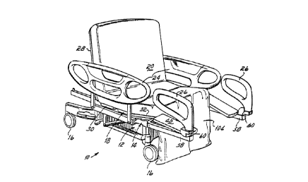
Referring to Fig. 1, a hospital bed 10 has a base
12 and a frame 14 mounted on the base 12. The hospital bed
10 has castors 16 for movement of the bed l0 about the
hospital. The bed 10 has a patient support platform 18
underlying a mattress 20 on which a patient 22 is situated.
At least a portion of the mattress 20 is preferably
inflated. The hospital bed 10 has patient side guards 24
and foot guards 26 for protection of the patient 22
situated atop the bed 10.
The patient support platform 18 can be converted
to and between a generally horizontal bed configuration and
a chair configuration as shown in Fig. 2. The patient
support platform 18 consists of serially hinged head 28,
seat 30, thigh 32 and foot 34 panels. Each panel is
pivotally attached to the adjoining panel as by pins or
other suitable mechanisms well known in the art. The foot
panel 34 consists of a central section 38 and a pair of
W O 95129658 ~ ~ ~ ~ ~ ~ ~ PCdIUS95105384
-10-
lateral sections 40, 40, one of which is pivotally mounted
to the thigh panel 32 on each lateral side of the central
section 38 as by a pin or bar 42 as shown in Fig. 3. The
central section 38 of the foot panel 34 consists of a
pivoting portion 44 which is likewise pinned to the thigh
panel 32 by the bar or pin 42 and a collapsing portion 46
which is smaller in cross-section than the pivoting portion
44 for telescoping into and out of a cavity 48 within the
pivoting portion 44. The collapsing portion 46 is biased
l0 by a spring 50 connected at a first end to a crossbar 52
secured to the collapsing portion 46 and at a second end to
a crossbar 54 secured to and underlying the pivoting
portion 44. In a preferred embodiment of this invention,
the collapsing portion 46 extends approximately 13 inches
(33 cm) out of the pivoting portion 44 of the foot panel 34
in the bed configuration.
The frame 14 of the bed 10 includes a U-shaped
frame section 56 at the foot end of the bed 10. The U-
shaped frame section 56 is open toward the foot end of the
bed 10 and includes a pair of arms 58, 58 to which one of
each of the foot guards 26, 26 is pivotally mounted at a
terminal end 60 thereof. With the patient support platform
18 in the bed canfiguration, the foot guards 26 are
generally collinear with each other and positioned at the
foot end edge of the bed 10 for protection of the patient
22 as shown in Figs. 1 and 3. In the chair configuration,
each foot guard 26 can be pivoted approximately 90° to be
positioned at the lateral side of the bed 10 to be
generally parallel with each other as shown in Fig. 2. The
foot guards 26, 26 in this position can be easily grasped
as a handhold by the patient 22 exiting the foot end of the
bed 10 in the chair configuration.
The patient support platform 18 is movable
longitudinally relative to the frame 14. A pair of forward
62, 62 and a pair of aft 64, 64 rollers are rotatably
WO 95/29658 PCT/US95/05384
-11-
mounted to a roller bar 66 which is fixedly secured by pins
67 to the seat panel 30 on each side of the bed 10 as shown
in Figs. 3, 4A and 5. The roller pairs 62, 64 are housed
and contained for rolling movement within a C-shaped
channel 68 secured to the frame 14.
To assist the platform 18 in longitudinally
moving relative to the frame 14, a first hydraulic cylinder
70 is pivotally connected as by a pin 72 to the U-shaped
frame section 56 and at a second end by a pin 73 to the
seat panel 30. A second hydraulic cylinder 74 is pivotally
connected as by a pin 75 at a first end to the roller bar
66 and secured via a link 76 at a second end to the foot
end of the head panel 28. The second hydraulic cylinder 74
is operational to pivot the head panel 28 from a generally
horizontal bed configuration upwardly to an upright chair
configuration as shown in Fig. 6. A third hydraulic
cylinder 78 is pivotally joined at a first end by a pin 79
to the roller bar 66~and secured at a second end to a link
80 at the foot end of the thigh panel 32. The third
hydraulic cylinder 78 is operational to pivot the interface
between the thigh panel 32 and the foot panel 34 upwardly
while converting the hospital bed 10 into the chair
position.
As shown in Figs. 2 and 4C, the foot panel 34 is
generally vertical with the bed 10 in the chair position.
To avoid interference between and contact with the foot
panel 34 and the floor as the foot panel 34 pivots
downwardly, the collapsing portion 46 of the central
section 38 of the foot panel 34 retracts into the pivoting
portion 44 through the operation of a pair of links 82, 84
connecting the foot panel 34 to the bed frame 14 as shown
in Figs. 4A-C. The first link 82 is pivotally joined as by
a pin 83 at a first end to the bar 52 secured to the
underneath side of the pivoting portion 44 of the foot
panel 34. A second end of the first link 82 is pivotally
~ ~ c~.~ ~,~,~
R'O 95129658 PCT/US95105384
r,
-12-
joined as by a pin 85 to a terminal end of the second link
84 projecting downwardly from the U-shaped frame section
56. A pair of posts 86, 86 each having a roller 88
rotationally mounted at an upper end thereof projects from
5, the upper side of the U-shaped frame section 56. Each
roller 88 is seated within a notch 90 of each of a pair of
blocks 92, 92 secured to the underside of the collapsing
portion 46.
The bed l0 of this invention is also equipped
with a patient lift mechanism 94 as shown in Figs. 8A, 8B,
9A and 9B for assisting the patient 22 in exiting the bed
10 from the chair position. The lift mechanism 94 includes
a four bar linkage 96 having a pair of generally vertical
links 98, 98 and a pair of longitudinal links 100, 101. The
four bar linkage 96 is connected to the base 12 and the
frame 14 of the bed 10 with a fourth hydraulic cylinder 102
pivotally joined to the middle portion of the upper
longitudinal link 100 and the base 12.
To enable the patient 22 egress from the hospital
bed 10 in the chair configuration, a portion 104 of the
mattress 20 overlying the foot panel 34 can be collapsed or
deflated as shown in Figs. 2, 9A, lOC and lOD.
The conversion of the bed 10 of this invention
from the bed position to the chair position is shown
schematically in Figs. l0A through lOD. The patient 22 is
in a supine position atop the mattress 20 with the patient
support platform 18 generally horizontal in the lowermost
vertical position (Fig. l0A). The foot end portion 104 of
the mattress 20 begins to deflate as the patient support
platform 18 shifts longitudinally relative to the frame 14
toward the foot end of the bed 10 (Fig. lOB).
Additionally, the head panel 28 pivots upwardly and the
interface between the thigh panel 32 and the foot panel 34
pivots upwardly. With the foot panel 34 generally vertical
and the collapsing portion 46 retracted into the pivoting
i WO 95129658 ~ ~ O '1 ~ ~ nj
01 f PCT/US95105384
-13-
portion 44, the patient 22 achieves a sitting position with
his feet contacting the floor directly (Fig. lOC). The
patient 22 is assisted in standing as the frame 14 elevates
relative to the base 12 (Fig. lOD).
In operation, to convert the bed 10 of this
invention from the generally horizontal bed configuration
to the chair configuration and thereby permit the patient
22 egress from the foot end thereof, the patient support
platform 18 is lowered vertically to the lowermost position
as shown in Fig. 8B. This can be accomplished by
retraction of the fourth hydraulic cylinder 102 thereby
collapsing the four bar linkage 96.
The patient support platform 18 is translated
longitudinally toward the foot end of the bed 10 by the
retraction of the first hydraulic cylinder 70 (Fig. 2).
The rollers 62, 64 secured to the seat panel 30 roll within
the C-shaped channel 68 secured to the frame 14. As the
platform 18 rolls toward the foot end of the bed 10, the
third hydraulic cylinder 78 extends (Fig. 6) to thereby
elevate and pivot upwardly the interface between the thigh
panel 32 and foot panel 34 by about 5° as shown by the
angle a (Fig. 4C). The second hydraulic cylinder 74
extends to pivot the head panel 28 upwardly.
As the interface between the thigh panel 32 and
the foot panel 34 pivots upwardly, the foot end of the foot
panel 34 pivots downwardly with the roller 88 extending
from the post 86 acting as a fulcrum point enabling the
block 92 and foot panel 34 secured thereto to pivot around
the roller 88 as shown in Figs. 4A-C. As the central
~ 30 section 38 of the foot panel 34 drops to the vertical
attitude and the interface between the foot panel 34 and
the thigh panel 32 pivots upwardly relative to the frame
18, the head end of the lateral sections 40, 40 of the foot
panel 34 also pivot upwardly. However, the lateral
sections 40, 40 do not drop below the frame 18 like the
W0 95/29658 ~ ~ ~ ,~ ~ ~ ~ PCTIUS95105384
-14-
central section 38 because the lateral sections 40, 40 are
supported by the arms 58, 58 of the U-shaped frame section
56 as shown in Fig. 7. .
The collapsing portion 46 of the foot panel 34 is
b~.ased by the spring 50 toward the outwardly extended bed
configuration shown in Fig. 4A. As the foot panel 34
pivots downwardly and the block 92 rotates about the roller
88, the foot end of the pivoting portion 44 of the foot
panel 34 pivots downwardly away from the frame 18 thereby
l0 extending the spring 50 and retracting the collapsing
portion 46 within the pivoting portion 44 of the foot panel
34. As the foot panel 34 pivots downwardly, the first link
82 likewise pivots downwardly thereby extending the spring
50, as the portion 46 slides into the recess 48 of foot
panel 34, and moving the foot end of the pivoting portion
44 downwardly away from the frame 18 until the foot panel
34 achieves the generally vertical attitude shown in
Fig. 4C of the chair configuration of the bed 10 of this
invention. In the chair configuration, the first link 82
and the second link 84 are in a generally vertical attitude
as is the foot panel 34 with the collapsing portion 46
telescoped into the pivoting portion 44.
With the bed 10 converted to the chair
configuration as shown in Figs. 2, 4C, 8A and 8B, the
portion 104 of mattress 20 is evacuated and a space is
vacated at the foot end of the bed 1o permitting the
patient 22 to egress from the bed 10. Advantageously, the
retracted foot panel 34 is vertical thereby enabling the
patient 22 to rest his feet directly on a floor surface
underlying the bed l0 (Fig. 8A) and thereby avoiding
confusion and inconvenience associated with the so-called
"false floor" effect. Similarly, the foot guards 26, 26 in
the chair configuration, the foot panel 34 in the retracted
vertical attitude, and the U-shaped frame section 56 at the
foot end of the bed 10 cooperate to vacate a space enabling
W0 95/29658 PCT/US95105384
-15-
patient egress from the bed 10 to a standing upright
position. Similarly, a wheelchair, motorized scooter or
motorized walker (not shown) can be docked into the vacated
space at the foot end of the bed 10 of this invention
thereby providing convenient transfer of the patient 22
from the bed 10 to the ambulatory assisting device.
To assist the patient egress from the bed 10 in
the chair configuration, the patient lift mechanism 94 is
provided with this invention as shown in Figs. 8A-B and 9A-
B. The fourth hydraulic cylinder 102 extends as shown in
Fig. 9B to pivot the four bar linkage 96 and raise the
frame 18 relative to the base 12 and urge the patient 22
from a sitting position to a standing or upright position
(Fig. 9A).
Referring now to Figs. 11-13, and in particular
first to Figs. 11-12F, and with like numbers representing
like elements, there is illustrated an alternative
embodiment of the bed 10 of the present invention. In this
form of the invention, the pivoting portion 38 and
collapsing portion 46 of the prior foot panel 34 are
replaced by a leg panel 200 which includes a calf
supporting panel 202 and a foot supporting panel 204. As
in the prior embodiment, calf supporting panel 202 is
pivotally connected to the thigh supporting panel 32 via
pin 42. Rather than the foot supporting panel 204
collapsing into the calf supporting panel 202, however, the
foot supporting panel 204 is pivotally connected on its
head end to the foot end of the calf supporting panel 202
via pins 206. A pair of identical, curved links 208, 208
3o pivotally connect each lateral side of calf supporting
panel 202 to a bracket 210 which is connected to the U-
section 56 of the bed frame 14. Each link 208 is pivotally
connected on one end via pin 212 to the panel 202 and is
pivotally connected on the other end to the bracket 210 via
pin 214. A second pair of straight links 216, 216
WO 95129658 PCT/US9510538.1
-16-
pivotally connect the lateral edges of the foot supporting
panel 204 to the U-shaped section 56 of the bed frame 14.
Each link 216 is pivotally connected on one end to the
panel 204 via pin 21s and is pivotally connected on the
other end to the frame section 56 via pin 220.
A mattress section 240 overlies the leg panel
200. Referring now to all the Figs. and particularly to
Fig. 13, the leg panel mattress section 240 includes a
continuous sheet of flexible material 242 to which is
attached on its underside a pair of pockets 244, 244 each
for removably receiving therein a resilient foam section
246. The sheet of material 242 includes a plurality of
grommets 248 along the head and foot end edges for
removably securing over the heads of screws 250 located on
the underneath side of the foot end edge of the foot
supporting panel 204 and the underneath side of the head
end edge of the calf supporting panel 202. Each of the
pockets 244 may include zippers or other opening and
closing means 252 for insertion of the resilient foam
sections 246 into and from pockets 244, 244. Each of the
resilient foam sections 246 includes an approximately 2
inch (5.08 cm) thick rectangular foam section 254 and an
approximately 2 inch (5.08 cm) thick strip 256 arranged
transversely on the head and foot ends of each of the
sections 254. Strips 256 may be secured to sections 254 as
by adhesives or the like or the strips 256 and section 254
may be formed iy an integral or one piece manner.
A second mattress section 260 overlies the
balance of the support platform 18 and includes arms 262
which overlie t,'he lateral portions 40 of the leg panel 200
as well as suitable fabric covering, etc.
As is seen in Figs. 12A-F, there being two
pockets 244, 244 with a small gap therebetween, which gap
is generally positioned over the interface of the calf and
foot support panels 202 and 204, the construction of leg
WO 95129658
PCTItJS95/05384
-17-
panel mattress 240 obviates or otherwise helps to reduce
bunching at that interface when the bed moves from the
general planar bed position of Fig. 12A to the chair
position of Fig. 12F. Furthermore, by utilizing a
5, continuous piece of flexible sheet material 242 the ends of
which are secured to the head end of the calf support panel
202 and the foot end of the foot support panel 204, the
sheet 242 is stretched tautly by the action of the panels
202 and 204 in going from the bed position to the chair
position thus compressing the foam sections 246.
More particularly, in referring to Figs. 12A-F,
it will be seen that in the bed position, foot support
panel 204 and calf support panel 202 are generally
horizontally oriented and lie within a common plane. In
moving from the bed position of Fig. 12A to the chair
position of Fig. 12F, it will be seen that calf support
panel 202 pivots through approximately 90° via the pivot
connection 42 and the action of the link 208.
Simultaneously, the foot support panel 204 moves through
almost 180° with respect to the calf support panel 202, or
almost 270° relative to its initial horizontal orientation.
Thus, in the chair position of Fig. 12F, the foot support
panel 204 is positioned aft of the now about vertical calf
support panel 202 and is generally juxtaposed to or against
calf support panel 202.
In use, and as with the prior embodiment, bed 10
is transformed from the planar bed position to the foot-
vacated chair position by pivoting head panel 28 upwardly
via hydraulic cylinder 74 (Fig. 3). The patient support -
platform 18 is translated longitudinally toward the foot
end of the bed with hydraulic cylinder 70. As the platform
18 rolls toward the foot end of the bed 10, links 216, 216
move foot panel 204 to a generally vertical position.
Continued longitudinal movement of platform 18 causes links
208, 208 to pivot the foot end of calf support 202
W0 95129658 ~CTIUS95/05384
,,;
-18-
downwardly and 'the head end of calf support 202 upwardly by
virtue of the traveling fulcrum effect of calf support 202
rolling over rollers 90, 90. The head end of calf platform
202 is free to 'translate upwardly by virtue of its pivoted
connection 42 to thigh panel 32 and the pivoted connection
of thigh panel 32 to seat panel 30. Continued longitudinal
movement of platform 18 causes calf support 202 to be moved
to a generally vertical position, and the foot support 204
to likewise be moved to a generally vertical position, but
aft of calf support 202 generally juxtaposed to or against
calf support 202.
The action of the panels 202 and 204 on the
mattress section 240 causes the sheet 242 to stretch tautly
around the joint 206 or interface between the panels 202
and 204. The tension in sheet 242 compresses the resilient
foam sections 246 thereunder thus providing additional
space for patient egress, docking of
ambulatory/rehabilitation modules, etc.
From the above disclosure and general principles
of the present invention and the preceding detailed
description of a preferred embodiment, those skilled in the
art will readily comprehend the various modifications to
which the present invention is susceptible. Therefore, we
desire to be limited only by the scope of the following
claims and equivalents thereof.