Note: Descriptions are shown in the official language in which they were submitted.
~ 1 8~ 1 ~2
METHOD AND APPARATUS FOR REDUCING NOX PRODUCTION DURING
AIR-OXYGEN-FUEL COMBUSTION
FIELD OF THE lNV~N~ ON
The present invention pertains to air-oxygen-
fuel combustion processes.
BACKGROUND OF THE I~V~N'1'10N
Most of the combustion processes used in
industry use air as an oxidizer to combust a fuel such as
natural gas, fuel oil, propane, waste oils, other
hydrocarbons and the like. Performance of many air-fuel
combustion processes can be improved by enriching the
combustion air with oxygen. Enrichment of the combustion
air increases both the flame temperature and the thermal
~,- 2la~l42
APC-510 - 2 -
efficiency while the flue gas volume decreases as the
oxygen concentration in the oxidizer increases.
Increased costs due to the use of high purity oxygen for
enrichment can be offset by gains in productivity from
enhanced combustion. ~ow level enrichment of up to 35
total oxygen content in the oxidizer can generally be
applied to existing air-fuel systems with only a few
modifications to the system.
Low level oxygen enrichment in combustion can
cause dramatic increases in NOX emissions. Under the
U.S. Clean Air Act, there are regulations, if not
incentives, for controlling the NOX formations as a
result of combusting air-fuel mixtures in the presence of
oxygen. Most industrial combustion processes producing
NOX emissions result in over 90~ of the NOX emissions
being in the form of nitric oxide or NO. It is known
that high levels of oxygen enrichment, e.g. above 90~
total oxygen content in the oxidizer, produce less NOX
than using air at the same firing rate. However, high
levels of oxygen enrichment can be uneconomical for a
given process and in fact may lead to problems with
equipment.
U.S. Patent No. 5,308,239 discloses and claims
a method for reducing NOX production during air-fuel
combustion processes utilizing oxygen enrichment.
U.S. Patent No. 5,217,363 discloses and claims
a method and apparatus for using air-oxygen techniques
for combustion of hydrocarbon fuels wherein the air is
primarily used to cool the burner-during firing.
-i_
APC-510 3
U.S. Patent No. 4,797,087 discloses and claims
a method and apparatus for using air-oxygen techniques
for combustlon of hydrocarbon fuels.
SUMMARY OF THE INVENTION
The present invention provides a method and
apparatus for air-oxygen-fuel combustion to increase
productivity while m;n;m; zing NOX formation. Oxy-fuel
combustion takes place in a post-mix or nozzle-mix
burner. Air is introduced around the oxy-fuel combustion
so that the air is directed along what would be a
longitudinal axis of the oxy-fuel flame at an angle
between slightly greater than 0~ to 90~ to the axis of
the oxy-fuel flame. In the preferred embodiment of the
invention the velocities of air, oxygen and fuel are the
same with each being less than two hundred feet per
second (200 fps).
BRIEF DESC~IPTION OF THE DRAWING
Figure 1 is a longit~ n~ 1 schematic cross-
section of an apparatus according to the present
invention.
Figure 2 is view taken along line 2-2 of Figure
1.
Figure 3 is a longitudinal schematic cross
section of an alternate embodiment of the present
invention.
Figure 4 is a longitudinal schematic cross
section of another embodiment of the present invention.
~ ~ 8 2 1 4 2
Figure 5 is a longitudinal schematic cross section of a
burner used in comparative testing of the method and apparatus
of the present invention;
Figure 6 is a plot of oxygen enrichment against NO
produced when testing the burner of Figure 3;
Figure 7 is a plot of oxygen enrichment against NO
produced when testing the burner of Figure 4;
Figure 8 is a plot of oxygen enrichment against NO
produced when testing a modified burner of Figure 4;
Figure 9 is a plot of oxygen enrichment against NO
produced when testing the burner of Figure 5; and
Figure 10 is a plot of oxygen enrichment against NO
produced for the burners of Figures 3, 4 and 5 fired without
use of a burner block.
DETAILED DESCRIPTION OF THE INVENTION
It has been shown that thermal efficiency of air-fuel
combustion processes can be improved by the use of oxygen
enrichment techniques. To this end, the process described in
U.S. Patent No. 5,308,239 has provided industry with a method
for retrofitting conventional air-fuel processes to take
advantage of oxygen enrichment techniques.
Referring to Figure 1, a burner shown generally as 10
according to the present invention includes a central fuel
conduit 12 having a first or combustion end
~,
.~
'~ 218~
APC-510 - 5 -
14 and a second or fuel supply end 16. Conduit 12 is
surrounded by a concentric conduit 18 having a first or
combustion end 20 and a second end 22 which comml]n;cates
with an oxygen supply manifold 24 as is well known in the
art. As shown in Figure 2, the conduit 12 and the
conduit 18 are generally concentric to each other and
define at their combustion ends 14 and 20 a post mix or
nozzle mix oxy-fuel burner nozzle or outlet.
Disposed around the oxy-fuel conduit 18 is an
air-fuel chamber or a passage 26 which communicates with
an air manifold 28 for introducing air into the chamber
26. The forward end of chamber 26 terminates in a face
plate 30 which contains a plurality of equally spaced air
passages 32. Plate 30 is disposed at an angle to the
longitudinal axis of the fuel conduit 12 so that air
introduced through fitting 28 into chamber 26 exits
through holes 32 at an angle to the longitudinal axis of
the fuel conduit and therefore the oxy-fuel burner.
Preferably, the angular relationship of the axis of the
holes 32 and the axis of oxy-fuel burner is greater than
0~ and up to 90~. The burner 10 can be disposed in a
burner block 40 so that the burner can be readily mounted
in a furnace. However, as will be more fully explained
hereinafter, the burner block is not necessarily
required.
Thus, in its basic form, the present invention
permits the combustion of an oxy-fuel flame which is
surrounded by air so that the total oxygen supply is
through a combination of pure oxygen and the oxygen
contained in the air, the process of the invention
reducing the total amount of N0 produced by the
combustion process.
~ 2 7 ~
APC-510 - 6 -
In the burner and the process according to the
'239 patent, it was found that by increasing the fuel
supplied to the oxy-fuel portion of the burner and
passing less fuel through the air-fuel portion produced
the lowest amount of NOX. A burner according to Figure 1
and 2 herein improved the ability to lower the NOX by
completely eliminating the fuel for the air-fuel portion.
In addition, the introduction of the air in a different
manner yielded lower fuel, oxygen and air velocities
which further reduced the NOX by as much as 80% in
comparison to the burner of the '239 patent.
According to the present invention, it was
found that the overall oxygen to fuel ratio should be at
or near stoichiometric. The actual ratio depends on
several factors. In a process which has a large amount
of air infiltration, the ratio should be on the fuel-rich
side to m; n;m; ze NOX without producing too much carbon
monoxide. In a process where oxidation of the product is
a concern, the ratio should be fuel rich even where ~here
is air infiltration. Any unburned fuel like carbon
monoxide, can be post-combusted to avoid unacceptable
emissions in the exhaust stack. In a process where fuel
may be liberated, such as in waste incineration, the
ratio may be more on the fuel lean side to provide
sufficient oxidizer to burn the extra fuel, if air
infiltration to the process is insufficient. In general,
it is desired to operate burners according to the present
invention as close to the stoichiometric ratio as
possible to m;n;mi ze NOX emissions without creating a
problem with carbon monoxide and combustibles emissions.
According to the present invention, the total
oxygen enrichment level should be greater than 40~.
~ 8 ~
Operating the burner between 25 and 40% enrichment would be
undesirable and operation below 25% enrichment would probably
not be economical because the small amount of oxygen would
provide few process benefits, increase NOX compared to air-fuel
only operation, and add to equipment and maintenance costs.
As a general principle for a combustion system operating above
40~ oxygen enrichment, the higher the enrichment level, the
lower the NOX production. A series of tests were run in a
furnace approximately 17 feet long, 7 feet wide and 6.5 feet
high. The floor of the furnace was made of refractory bricks,
with the end walls, lower sidewalls and roof lined with a high
temperature ceramic fiber blanket. The upper sidewalls of the
furnace were filled with water to simulate a furnace load. The
furnace contained a flue in one end wall approximately 20
inches in diameter with a water cooled damper to control
furnace pressure. The burner was centered approximately in the
other end wall.
NOX was measured with a Beckman model 865 non-dispersive
infrared analyzer. Carbon monoxide and carbon dioxide were
measured with Beckman model 864 non-dispersive infrared
analyzers. Oxygen was measured with a *Taylor-Servomex model
08.244 paramagnetic analyzer. Nitrogen and carbon monoxide
were also measured with a Hewlett Packard gas chromatograph.
Gas samples were extracted from the flue with a vacuum pump
through a stainless steel water cooled probe. These samples
were immediately cooled with a condenser to remove most of the
water from the gases and the samples were transported through
Teflon tubing for further drying with a desiccant and a
membrane dryer before being injected into the analyzers.
Sample dew points were generally below 0~F indicating a very
dry sample.
*Trade-mark
,.
218~
' .M~..
.~~
APC-510 - 8 -
The oxygen used for the test was 99.5~ minimum
purity. The natural gas used as a fuel had a composition
by volume of 94.28~ CH4, 3.04~ C2H6, 0.83% C3H8, 0.34~
C4H1o, 0.12~ C5H12, 0.06~ other hydrocarbons, 0.49~ N2,
0.82~ CO2. For this fuel, the higher heating value is
about 1032 Btu/ft3. For this composition, the
theoretical stoichiometry for perfect combustion, (based
on total oxygen from air and oxygen streams) is about
2.04 In this context stoichiometry is based on the
volume flow of oxygen, (air + ~2) in the oxidizer divided
by the volume flow of natural gas.
The burner of the '239 patent was simulated by
replacing the oil nozzle of a North American model 6514
dual fuel burner with an oxy-fuel burner. The oil nozzle
was removed, and an oxy-fuel burner was inserted through
the middle of the model 6514 burner. The burner
according to the present invention was as shown in Figure
1. Table 1 below sets forth a typical set of operating
conditions along with NOX results for a burner operating
according to the '239 patent and according to the present
invention.
TAB~E 1
Parameter '239 BURNER Fiq 1 BURNER
overall equivalence
ratio 0.890 .88
overall oxygen enrich-
ment level (vol~) 51 46
overall firing rate
(MMBtu/hr) 2.5 2.5
furnace pressure
21~142
. .~,.
.~_
APC-510 9
(in. H20) 0.05 0 05
average furnace
temp. (degF) 2385 2070
NOx (lb/MMBtu) 0.514 0.096
Under similar firing conditions, the burner
according to the present invention produced significantly
less NOX than the burner according to the prior art. It
was also observed that the flame produced by the burner
according to the present invention was much larger and
more luminous than the prior art burner.
It is believed that the burner of the present
invention produced lower NOX than the prior art burner
because of the use of only three gas passages instead of
four coupled with the arrangement of the gas passages in
the new burner. In the prior art there are three
reaction zones (sometimes referred to as flame fronts or
flame sheets). These are at the interface of the fuel
and oxygen passages in the oxy-fuel portion, at the
interface of the fuel and air passages in the air-fuel
portion and in the interface between the oxygen of the
oxy-fuel and the fuel of the air fuel portions. In the
burner according to the present invention, there is only
one reaction zone which is between the fuel and oxygen
passages. These reaction zones are where the fuel is
reacted when the mixture concentration of the fuel and
oxidant is in the flammable range. It is believed that
this is where much of the NOX is formed due to the higher
temperatures at these locations. It is also possible
that the lower NOX is produced with the burner according
to the invention because of the shielding of the air by
the oxygen. It is believed that the oxygen in the burner
2i8~
. .,
APC-510 - 10 -
according to the present invention acts as a shroud to
keep nitrogen in the air supply from quickly mixing with
the ~uel thus keèping nitrogen out of the hotter part of
the flame which in turn helps to reduce the formation of
NOX.
It should be stressed that one of the key
features of the present invention is that the gas
velocities should be low and as close to equal as
possible. The use of low velocities of equal measure
m1nlm; zes mixing and stretches out the flame making the
flame more uniform in temperature without high peak flame
temperatures that are common in conventional air-oxygen-
fuel of burners (e.g. U.S. Patents '239, '363 and '087).
According to the present invention, the maximum
benefits in reducing the formation of NOX are achieved
when the velocity of the air, the velocity of the natural
gas and the velocity of the oxygen are approximately
equal and less than 200 feet per second. Introducing the
air through a plurality of apertures or passages,
approximately 12 in number, also aids in achieving the
maximum benefit of the invention.
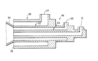
Further tests were conducted on alternate
embodiments of the invention. Figure 3 shows a burner 49
containing a central fuel conduit 50 surrounded by an
oxygen conduit 52 having a flare deflector 54 in the
shape of a truncated cone whose sides are at an angle
approximately 45~ to the center line of the burner.
Surrounding the oxy-fuel burner 50,52 is an air conduit
56. Fuel, e.g. natural gas is introduced to the conduit
50 via fitting 51, oxygen is introduced to conduit 52 via
fitting 53 and air is introduced to conduit 56 via
2 ~ 2
,.,
APC-510 - 11 -
fitting 57. A burner 49 according to Figure 3 was
fabricated using stainless steel piping and fittings.
The fuel passage 50 was fabricated from a 2.5 inch
schedule 80 pipe (2.323 inches id by 2.875 inches od).
The oxygen conduit 52 was a four inch schedule 40 pipe
(4.026 inches id by 4.500 inches od) and the air conduit
56 was a 6 inch schedule 40 pipe (6.065 inch id by 6.625
inch od). The flare 54 in the version shown in Figure 3
projected one inch beyond the end of the burner 59.
Figure 4 is a burner that is identical in
~;m~n~ions to the burner of Figure 3 except that the
flare 54' only projects one half inch beyond the end 59
of the burner 49.
Figure 5 is a schematic representation of the
burner 49 of Figures 3 and 4 without the flare.
The burners of Figures 3, 4, and 5 were
designed , fabricated and tested for firing at a rate of
3 million Btu per hour with an oxidizer (air plus
oxygen) containing 46.5~ oxygen and gas (air, oxygen,
natural gas) velocities of about 25 feet per second.
A burner according to Figure 3 was fired in the
test furnace at the rate of 3 million Btu per hour with
an oxygen to natural gas stoichiometry in the range of
2.3 to 2.5, a furnace pressure in the range of -0.07
inches to 0.07 inches water column and an oxygen
enrichment in the range of 30 to 80~. Oxygen enrichment
is defined as:
~2 enrichment = total volume Of ~ 2 supplied through the burner
total volume of ~ 2 + N 2 supplied through the burner
218~142
,
APC-510 - 12 -
The carbon monoxide level ranged from 100 ppm
to greater than 5000 ppm. For the purposes of these
tests, ppm refers to parts per million by volume on a dry
basis. Most of the data were taken at a furnace pressure
of about 0.05 inches water column and an oxygen to
natural gas stoichiometry of 2.4. The stoichiometry was
intentionally maintained at a high level because the
burner produced a black soot at lower stoichiometries.
Production of soot at the test site is prohibited.
Figure 6 is a plot of oxygen enrichment against
NO produced wherein the burner was employed with a burner
block such as shown in Figure 1 having a length of 0
inches (no burner block) six inches and twelve inches
- measured from the end of the burner. Figure 6 shows that
NO levels were lowest where no burner block was used and
at the lowest enrichment of 30~.
A second set of data was collected using a
burner such as shown in Figure 4 fired at rates ranging
from 3.0 to 5.0 million Btu per hour with a stoichiometry
ranging from 1.6 to 2.5 O2/natural gas. The furnace
pressure was about 0.05 inches water column and the
oxygen enrichment ranged from 30 to 80~. Figure 7 shows
the results of the data taken where the burner was fired
in burner blocks having the ~;men~ions shown. As shown
in Figure 7, NO production increased with oxygen
enrichment. The burner block having a 14 inch inside
diameter and a 7 inch length generally produced the
lowest amount of NO. In general, the wider or shorter
burner block produced less NOX. Comparing Figures 6 and
'~ 21 ~1 42
APC-510 - 13 -
7, the burner of Figure 4 produced less NOx than the
burner of Figure 3.
The burner of Figure 4 was modified by drilling
a series of 17 0.5 inch diameter holes equally spaced
around the conical portion of the flare. The burner was
fired at 3 million Btu per hour and a furnace pressure of
about 0.05 inches water column. The results of these
tests are plotted in Figure 8 wherein the burner was
fired with a stoichiometry of about 1.7. The NO level
for the burner fired without a burner block (0 inches L)
which was as low as 0.057 lbs. per million Btu was
generally lower than that for the burner fired with the 7
inch long burner block. Again, NO increased as the
oxygen enrichment decreased. Due to the fact that the
burner block was fairly wide (14 inches id) there was not
as much difference in the NOX for the burner fired
without a block as opposed to the use of a 7 inch burner
block although in general no other burner block again
produced less NOX. The NOx levels in Figure 8 are very
low because the burner could be fired at a stoichiometry
of 1.7 without producing excessive soot. This is due to
the increased mixing of the fuel and oxygen caused by the
holes in the flair cone.
A final set of data was collected utilizing the
burner of Figure 5 wherein the burner was fired at a rate
of 3 million Btu per hour, a furnace pressure of 0.05
inches water column, oxygen enrichment ranging from 30 to
80~ and a stoichiometry ranging from 1.6 to 2.5
oxygen/natural gas. Figure 9 compares NO produced
utilizing three different burner block configurations
with a stoichiometry of approximately 1.6. As shown in
Figure 7, the NO produced was lowest when no burner block
' 218214~
.
APC-510 - 14 -
was used. The lowest NO produced was about 0.04 l~s.
NO/MMBtu. At that stoichiometry, all NO measurements
were low. Again, as shown in Figure 7, firing the burner
without a burner block generally produced less NOX than
with a burner block being used.
Figure 10 compares the production of NO for the
burners shown in Figures 1, 3 (full flare), Figure 4
(half flare) and Figure 5 (no flare) fired at 3 million
Btu per hour and a stoichiometry of 2.3. For the
comparison of Figure 10, the full flare Figure 3 burner
was fired at a furnace pressure of 0.01 inches water
column, the half flare (Figure 4) burner with holes was
fired at a furnace pressure of 0.05 inches water column
and the no flare (Figure 5) burner was fired under a
furnace pressure of 0.05 inches water column. As shown
in Figure 10, the burner of Figure 5 generally produced
the lowest NO, regardless of the differences in furnace
pressure. For burners of the type shown in Figures 3, 4,
and 5 NO began to decline about 40~ oxygen for the half
flare and no flare burners. According to adiabatic
equilibrium predictions, that is about how the NOX curve
would look. For the burner of Figures 1 and 2, the NO
began to decline at levels of about 30~ oxygen. The
burners of Figures 3, 4 and 5 would probably be operated
in a commercial application by setting the stoichiometry
at about 1.5. This is because air infiltration generally
increases the effective stoichiometry and because the
industrial user, (e.g. aluminum melter) does not want to
oxidize any of the molten metal in the furnace which
would in turn lower production yields. The burners could
not be run in the test furnace at a stoichiometry of 1.5
because of the production of a very smokey/sooty exhaust.
In an aluminum melting furnace, for example, it would be
~ ~ ~ 2 ~ ~ Z
- 15 -
a longer residence time and enough ambient air leakage both
into the furnace and into the exhaust stack so that the exhaust
to the atmosphere would not be smokey/sooty. According to the
test discussed above, burners with a full flare and with a half
flare (no holes) produced very sooty flames. These burners had
to be run at a stoichiometry of about 2.3 to avoid producing
excessive smoke/soot and exhaust. The burners with the half
flare (with holes) and no flare could be run at stoichiometry
as low as 1.6 without causing excessive smoke or soot. Burners
run without a burner block generally produced less NOX than
those same burners run with a burner block. Shorter and wider
burner blocks produce less NOX than longer and narrower blocks.
Introducing holes into the flare reduced the NOX in comparison
to the flare with no holes. No flare on the burner produced
the least amount of NOX. All of the burners of Figures 3, 4
and 5 produce less NOX than the burner of the '239 patent but
produce more NOX than the burner shown in Figures 1 and 2.
The key benefit of the method and apparatus of the present
invention is the lowered NOX production when the burner is in
use. This is achieved by a burner using fixed nozzles having
the specified angular relationships, introducing the air as a
plurality of streams around the oxy-fuel flame and matching the
velocities of air, oxygen and fuel preferably at values below
200 fps.
Having thus described our invention, what is desired to
be secured by Letters Patent is set forth in the appended
claims.
.~