Note: Descriptions are shown in the official language in which they were submitted.
CA 02182255 2006-11-15
CA1-011.P01
1
DESCRIPTION
'WEIGHT DISTRIBUTING HULL AND KEEL SUPPORT
FOR BOAT TRAILER FRAMES
Technical Field
The present invention relates to boat transporting trailers, and more
particularly to hull engaging and supporting elements in such trailers.
Background Art
Numerous boat trailers have been developed in the past with specific
accommodations for receiving and distributing the weight of a boat between
rollers or elongated flexible "bunks" engaging the boat hull.
The keel area of a boat is typically designed to be relatively strong, while
the hull areas are much more fragile. It is therefor desirable for the support
devices in a boat trailer to engage the boat hull over a fairly large surface
area
to provide partial support and to support the remainder of the boat along the
keel area.
It is desirable to provide a share of support along the keel, because the
keel is typically the strongest area on a boat. However, it represents only a
small fraction of the total surface area for potential support. When only keel
support is provided, stability of the boat on the trailer is minimal. An
"ideal"
support will proportion the received weight of the boat in a desired
relationship
between keel supports and hull supports.
US Pat. No. 5,255,933 granted to the present applicant discloses a much
needed solution to the above problem by provision of a boat hull support
arrangement that will automatically adapt to individual hull configurations
while
maintaining a desired weight support ratio between the hull and keel engaging
members thereof.
A need remains, however, for such a trailer with the above qualities, but
with improvements that will facilitate loading and unloading of boats in
relatively
shallow water, or in areas where the trailer cannot be backed far into the
water
for loading or unloading purposes.
Brief Description of the Drawings
Fig. Y is a side elevation view of a boat and trailer incorporating features
of a first preferred form of the present invention;
Fig. 2 is a rear view of the first preferrzd form with a boat mounted
thereon;
CA 02182255 1996-12-19
CAI -OIr.POI
2
Fig. 3 is a rear view similar to that shown in F'ig. 2, only showing an
alternate form of short bunVic engaging the transom errd of a boat;
Fig. 4 is an enlarged, fragmented side view of a rear portion of a
preferred form of the present improvement;
Fig. 5 is an enlarged, fragmcnted side view of a frorat portion of a
preferred form of the present improvement;
Fig. 6 is a view similar to Fig. 4 only sllowing a diff'erent operational
position of the elements shown;
Fig. 7 is a view similar to Fig. 5 only strowing a diffet=ent operational
1o position of the eleme.rits shown;
Fig. 8 is a fragmented view sinlilar to Fig. 1 only showing the trailer
unloaded;
Figs. 9-11 are diagrammatir, operational views sliowing a boat being loaded
onto the present trailer;
Fig. 12 is a view similar to l:"ig. 4 only showing the alternate form of
short bunk;
Fig. 13 is an enlarged ser.tit,mtrl view taken substantially along line 13-13
in Fig. 4;
Fig. 14 is a view similar to Fig. 8 only showing the interconnected short
2o and long bunk configurations without a weight shrfting means;
Fig. 15 is a view similar to Fig. 8 onlv showing the long bunk and weight
shifting means without the short hunk .:rsscrnhly;
Fig. 16 is an enlarged. fragmented view showing anothcr preferred form
of the weight shifting means;
Fig. 17 is a side elevatiorr view illustrating the weight shifting means of
Fig. 16 with the long bunks and without the short bunk assembly.
Best Modes for Carrving Out the Invention and Disclosrire of Cnvention
A trailer embodving aspects of thc present invention is shown in the
accompanving drawings anc:i is desigrtated therein by the refcrerrce numeral
11.
3o The boat trailer 11 incorporates tiln cloragated rigic9 Prttmework 1' that
serves to
mount the present improved hull and keel support generally designatcd at 10.
For purposes of' further description, a brief description wiil be given with
regard to the boat trailer frGlme 12, f3rictly, thr boat traile:r 11 will
typically
include an clongatecl frame. 12 oxtcndirlg he.rwt:.e.n a rearward crrd 13 and
a
forward end 14. I'hc c;xemplific:d tr<dilcr is supported bv wheels 15 and
includes
transversely spaced longitudinal fr,3nfc sidc rlrcrnhcis 16 . Further dctails
of thc
CA 02182255 2006-06-06
. ti
3
trailer frame will not be given, it being understood that such frames are well
known to the industry. The elements described below may be utilized for a
variety of such conventional boat trailer frame configurations.
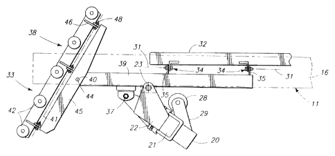
In general, the present invention includes a pair of rigid rearward and
forward cross members 20, 51 pivotably mounted to the trailer frame 12.
Rearward cross member 20 is situated near the rear trailer end 13, and forward
cross member 51 is located toward the forward trailer end 14.
The rearward cross member 20 extends transversely to the trailer frame
between opposed ends 21 (Figs. 2 and 3) that are mounted by brackets 22 to the
elongated trailer frame side members 16. The brackets 22 are mounted by bolts
or
other appropriate pivot connectors to facilitate pivotal motion of the
rearward
cross member 20 about a horizontal rearward fulcrum axis 23 (Figs. 4 and 6)
that
is transverse to the longitudinal orientation of the frame 12.
In the illustrated examples, a keel receiver 28 is mounted to the rearward
cross member 20 by means of a bracket 29 (Figs. 4 and 6). The keel receiver 28
is
advantageously in the form of a roller or pairs of rollers that are mounted to
one
side (preferably forward) of the rearward fulcrum axis 23. The keel receiver
28 is
positioned substantially centrally on the rearward cross member 20 to receive
and
provide moveable support to a boat keel.
The exemplified forms also include elongated bunks 32 for receiving and
engaging the boat hull. The elongated bunks 32 are operatively mounted at
rearward ends to the rearward cross member 20 and are laterally spaced from
the
keel receiver 28. It is preferred that at least one pair of the elongated
bunks be
provided, with each member of the pair being spaced a lateral distance from
the
keel receiver 28.
The configuration of the elongated bunks 32 may vary as disclosed in U.S.
Patent No. 5,255,93. In the preferred form the elongated bunks 32 are flexible
along their lengths. The bunks 32 extend along and are substantially parallel
to
the side members 16 of the boat trailer 11.
A mounting means 34 is provided in a preferred form for operatively
connecting the elongated bunk members 32 to the cross members 20, 51 such that
the cross members 20, 51 are linked together by the elongated bunk members 32.
Weight of the boat is distributed to the trailer frame by elements described
below
between the mounting means 34 and the cross members.
CA 02182255 1996-12-19
CAl-O11.P01
4
Mounting means 34 includes longitudinally spaced paired hinge
assemblies 35 mounting rearwar-ei ends of ttle c]ongrrted bunks 32 to forward
ends
of rigid elongated longitudintal yoke.s 39, om: otwhich is provided f'or each
elongated bunk 32. "I'he hirlge assernblies 35 are positiorled at forward ends
of
the yokes 39, forward of the fulcrutn axis 23.
The hinge assemblies ;5 permit the elongated bunks 32 to pivot on
longitudinal axes 31 to conl'orrn angularly to various hull configurations.
However, each of the paired hinge assernbli:es rr7ount the associated bunk 32
and
yoke 39 rigidly along their lengths, so the yclk:es ~19 becorne substantially
a rigid
la extension of the bunks 12. 'I'llis is done to strengthen the connection
between
the yokes and bunks, ancl to hold the rearward erids of the bunks 32
substantially parallel to the yokes ;"'9 at all tinles.
The yokes 39 are paircd on tlle rearward cross niember 20, each being
spaced to an opposite lateral side of thc keel receiver 28. The pair of
elongated yokes 39 are pivotably rnc:lunted at yoke pivots 37 to the rearward
cross member 20 ancl extend lon:irr.ldinallv hctwee,n l'orward and rearward
yoke
ends. In a prefe.rred fornl, the vr.akes39 10ngiCudiMllly overlap the rearward
fulcrum axis 23, with the yoke pivots 77 being r,itu;ltc.d rearwardly oF the
fulcrum
axis 23.
In one preferred form, rearward ends of thc: yokes 39 mount short bunks
38. The short bunks 38 are pivot;lhlvnnounted to the yokes 39, rearwardly of
the fulcrum axis 23 and the yoke pivot;; ~7. "1'hc short bunks 38 pivot
relatively
freelv on transverse short hunk pivot a.xes 40, defined by pivot pins 44. The
short bunk pivot axes 40 itre preCerrably sub~ztantiallv parallel to the
rearward
fulcrum axis 23, and to the yoke pivots 3?.
The short bunks 38 pivot on the t.ransverse axes 40 between first positions
(Fig. 4) in substantial longitudinal Rriignme.nt with the elongated bunks, and
angularly inclined second positions (Fig. 6). The short bunks 38, when in the
angularly pivoted second positions are useful in the boat loadirlg operation
as
shown in Figs. 9-1 1.
Hull engaging nzembe.rs :33 ;ire ancluded on the short hunks 38 and pivot
about longitudinal member pivOt ilxcs u11 that ,.lre. substantially
perpendicular to the rearward fulcrurn axis -',, and tlic lrt111sVCrSC shurt
bunk pivt,t axis 40. The
longitudinal pivot axes 41 arc substrlntir.111y horizc7ntai in thc: 1erldc;d
conciition oF
the trailer, and are oriented icacigiouxlintiillv witlx rcapect to thc;
elongated boat
traiier frame f:.?. The axes 41 in this positimrr arc substantially coaxial
with the
CA 02182255 1996-12-19
CAI.O11.P01
~
long bunk axes 3 1. The angular orientations c.al' the axes 41 will change as
the
bunks are moved about the short hunk pivot axes 40 (see Fig. 6).
In one preferred form, the EruNI engaging members 33 include a plurality
of freely rotatable rollers 42. The rollers 42 are positioned to
longitudinally
align with the top support surfaces of the elongatc.d bunks 32 (Figs. 1, 4)
when
the trailer is loaded. The rollers 42 will thw, engage a boat hull in the same
manner as the elongated bunks 12 when a bo<:rt is loaded on t[ie trailer 11.
In an alternate form (Figs. 3 and 12), the itull engaging members include
elongated flat boat hull engaging suri'aces 43 mounted thereon. 'I'he surfaces
43
lo resemble the elongated hunks 32. hut W'e sub?,,tWItially shorter, and are
coplanar
with the hull engaginE; surfaces ot' the iA]_.er brrrol;.s when a boat is
fully loaded
on the trailer.
In either form, the short bunk rnt.:mber~ 38 are pivotable on the rearward
cross member 20 about the longitudinal short bunk: pivot axes 41, and the yoke
pivots 37.
In the preferrcd embodiments, the sl-wort bunks i8 also include rigid
elongated brackets 45 with transvcrse, ~1:e,ntrall.y locat~~.d pins 44, The
pins 44
extend through the elongated brackets 45 and yc:7kcs _i9 to definc the
transverse
short bunk pivot axes 40 (Fi~s. arid l "2o The elongated brackets 45 are ot an
inverted "U" shape and are loosely
fitted over the yokes 39. The brackets 45 also include upstanding hinge plates
46 with hinge pivot. pins 48 that are mounted by brackets 49 to the hull
engaging members 31. I?ins 44, 48 dctinc- tlic: respective transverse and
longitudinal short bunk pivot axes 40 ;an(:i 41, Tllc lungitudinal short bunk
pivot
axes 41 are substantially coaxial with thc lr~)ngiÃudinal pivot <Ixis 31 of
the
elongated bunks 32, as defined by the hinged l.rlates 35, when the trailer is
loaded.
It is of interest to riote the relative distanc-e B (Fig. 4) between the keel
receiver 28 and the rearward fuicrusrr axis 23, and the distance A from the
yoke
pivot 37 to the fulcrum axis 23. 'I'he.se distances determine the proportion
of
weight supported on the re:;psr:ctivc cIc:rngated and short hunks _?2, 38 and
keel
receiver 28.
By way of example, it has been t'ound to hc; <Idvantageor.ls to space the
keel receiver 28 to a side uk the rearward fulcrum axis 23 such that thc kcel
receiver 28 will be<dr approxintatelY Iorty lrurcQn~ ol' the boat weight at
thc:
rearward cnd of thc: trailer whiEc tlir: hunk,, 32, 38 bear approximately
sixty
CA 02182255 1996-12-19
CA 1-0i 1. P01
6
percent of the load. This rclationship may he changed as desired simply by
adjusting spacing from the rearward t'ulcrum axis to the keel receiver 28 and
yoke pivot 37.
It is also of significance to note that the transverse short bunk pivot axes
40 and yoke pivots 37 are pKarallel to the horizontal rearward Culcrurn axis
23.
By this provision, the axes 40 arld pivots 37 'will always remain in a
horizontal
orientation regardless oE the pivotcd prasition 4 the rearward cross member
20.
Thus, the elongated bunks ;a2 and short bunks 18 may remain in an angular
orientation capable of intimate contact with the ho<at hull, at any pivoted
position
lo of the rearward cross member 20 and the kecl re ceivcr 28. This feature
thus
lends the ability for the present support sy:xtcm to instantaneously and
automatically adapt to various boat huil cont:iimurations.
In preferred forms, a fc,arwarr.l cross rncrtlber 51 (Figs. 5, 7, 16) is
provided. Mounting brackets 53 arc provided at onds ol' the cross member 51
to mount the forward cross rnerrtbe.r '7 I lor pivotai motion about a forward
fulcrum axis 54. The forward tuli:rum axis 54 is parallel to the rearward
fulcrum
axis 23. Axis 54, like the rearward l'ulcrum axis 2:>, is preferably
horizontal, and
transverse to the longitudinal oricntatiori ot' the elongated frame: 12.
A keel receiver 56 is provided on thc forward cross mernber 51 at the
center thereot and is rruaunted bv brackets 57 to one side of the forward
fulcrum axis 54. In the c:x.lmp1c :,ltown. thc spacing hctween rcceiver 56 and
the forward fulcrum axis 54 is the sarrtc di:;tarlce 13 as shown in Fig. 4
between
the rearward fulcrum axis 23 and keel ri:ccavcr 2,8. Likewise, the distance A
between fulcrum axis 54 and axis 59 is the 5amc as shown between rearward
fulcrum axis 23 and pivots 37.
As shown in Fig. 5, the mountink mians 34 is provided with a gimbal
means 58 defining tirst and second li~lot axr..s 59, 60. Axis 59 is transverse
to
the trailer and substantially paraik t to tlle re.arward yoke ~pivots 37. An
axis 60
is longitudinal and coincidental with ~+xi., 31 (,~lA cR.dch sidc ot' thc
trailer.
The axes 59, 60 are :iet'incd on each ,ide o1* the trailer by pins 6:3 and
65 extending through (in the f'irtit prc.terrti.d ''orrn) mating, paired
gimbal
tlanges 62, 64 (Figs. 5 and 16) G)t' a g'imh;ti cos-c, 61. The pins mount the
gimbal corc (it between respectitic vclk+: brackcts 67, 68 on the bunk :32
and
forward cross memhcr 51.
Flangcs 02 in the i'irst prcir:rrcri l()rrn 111s-;ludc longitudinal slots 06.
Slots
66 lunction ~ls rnc,ln:; Cor [wrrnittinr lmr itut.limll t1etlcction oC thc
clongMcd
CA 02182255 1996-12-19
CA1-011.PO1
7
bunks 32 responsive to loa(iing and deflection thvreaaf against the hull
surface
of a boat. Slots 63 also perlnit independent pivotal motion of the forward and
rearward cross members 20, 51 about axes 54, 23 even though the members are
connected by the elongated bunk:> 32.
This feature mav he clc;arly understood by comparing Figs. 5 and 7. The
pin 63 in Fig. 5 is showri substantially midway along the slot 66. In Fig. 7,
the
bunk is shown under an unloading corlditicrn, such that the longitudinal
spacing
between the gimbal brackets at the t.lpposite ~;,nds of the elongated bunks 32
is
foreshortened.
The slot 66 aceommodates the fore.shortening by allowing the bunk 32,
yoke bracket 67 and gimbal corc ()l tt) skide rearwardly on pins 63. The
capability for the bunk to pivot abclut tllc: longitudinal short bunk pivot
axes 41,
and seconcl axes 60 of pins 48õ 65 remains t'lle same in both conditions.
Further, the load bearing relationship between the bunks 38. 32 and the keel
receivers 28, 56 rernains substantia9ly ttie same.
The elongated hunks 32 are therefore free to deflect along their lengths
within reasonable limits, by provision of the ;;lots 66. Yet the elongated
bunks 32 are independently moveable through arc.s defined bv the fulcrum axes
23, 54 of cross niembers 20 and 51 to indehaende.ntlv vary elevrttional
distances
between the elongated bunks K: tin(I the keel receivers 28, ';(i and thereby
autotnatically adjust for hulls o1 various depth!t; and bow-to-stern
configurations.
Additionally, the pins 48, hinge ttsserrtldies ')5, ancl pins t75 which define
the longitudinal slrort hunk pivot axes 41, axis 31, anci coincidental second
pivot
axis 60 permit pivotal motion ot the short bunks 3S and elongated bunks 32 to
still further enable adjustnlent: ol' the hunk posit,ons with respect to the
boat
hull configuration.
The various axes and the: rc:iationships therc:of facilitate a wide variety of
positioning for the bunk members and keel receivers to accomnlodate a similar
variety of hull cont'igurations.
In the preferred form, weight of the hoat hull supported between the
bunks 32, 38 and the keel recc;ivers 28, 56 rvill remain within a selected
ratio.
For example, should a weight distribution he tilc:sired as described above
(approximately forty percent for tiZc; keel rc .c.civcrs 28, % and
approximately sixty
percent Cor the hunks :'2. 8), that rc:i:ttiranst~.ip will remain relatively
consistent
regardless of the cIcvationai spacing hc~twc,cn thc k.ccl supports and bunks.
Thus
the same weight distributio?n will h, to ;i rclativelv dcep, "v" hull
CA 02182255 1996-12-19
8
conf'iguration, or to a sailboat witl~t a relativelv dc .ep keel, or to a boat
having
a flat or shallow hull its shown in l'igs. 2, and A. The bunks and keel
receivers conform closely to the hull and h:c:ci while weight distribution
remains
relatively consistent.
Fig. 14 is illustrativc c>f ttnotherexemplary embodiment of the present
invention in which the keel supports 28, 56 and the long and short bunks 32,
38 are provided as described above. 't'he supportive weight distributing
apparatus
is provided connectirrg the various bunks, kecl supports, and cross members to
the trailer frame. A trailer with this novel arrangement ot' components has
been
lo used experimentally to load, carry and unload boats of' various weights and
hull
configurations. 'I'he load support <tnt.t weight distribution advantages of
the
components was found to be substantially similmr, if not idcntical, to that
described in my U.S. Patent No. 5,255,9313. However, the present trailer was
found to include distinct advantages ~in loading and unloacling the boats,
brought
about by the combination including thw voke.s 39 anci short bunks 38. Fig. 14
thus represents a first pret'erred 1'orm ot' the preserit invcntion.
It is believed that additional loading and unloading advantages may be
gained by provision ot a weight shifting means 70 connecting the forward cross
member 51 to the trai3er lrztmc, 1 'I. In orre pret'r;rrecf fcrrm, the weight
shifting
means 70 may be utilized in the combination sho%vn in Figs. 8 and 12.
Alternatively, means 70 tnav he combined with a bunk and keel receiver
weight distribution arrangentent sirnilar to that disch:)sed in the above-
incorporated
'933 patent, and as shown in 15. In thi~, enibodiment, the short bunks 38
are eliminated and the rearward ends ot' the long bunks 32 are connected at
the
pivots 37, to the rearward cross inc~.rnk-,c:r 20,.
In a still fui-the.r prelerred form, the means 70 is integrated within the
hull support structure by a novel arrangemc:nt of the support geometry, as
exemplified in Figs. 16 and 17. Though not shown, this arrangement could be
substituted for the. form oi' weight shii'ting mc :ans 70 in the combination
shown
in Fig. 15.
In any of the forms exemplif'ied, the weiuht shifting means 70 is utilized
(selectively or automatically) to shift the.load sht:rred by the buraks 32 and
keel
receiver 56 at the bow end of the boat, nion: to t hc keel receiver 56, making
it easier to move the boat oi'i' thc trailc:.r. ~In cio;ng so the weight ratio
shared
by the long bunks 32 and the kc~el receiver '16 ttt the bow end of the boat is
CA 02182255 1996-12-19
CA 1 -u1 l.YO!
9
shifted so more of the bow weight is borne h~thc keel rcceiver 56 than by the
forward ends of the long bunks j'" .
This is accomplished in the fi:rsl. preferred form (Figs. 1, 5. 7, and 8) and
by selectively pivot.inf!, the fc.arward cross membc-r 51 on the forward
fulcrum axis
54. The pivoting cross member :51 will sirnuli.aner~usly lift the keel
receiver 56
upwardly and lower the forwaid ends of the hunks 327.. This novel arrangement
requires minimal shifting of the bunks ancf receiver, since both are moved
simultaneously in opposite elevational directions,
It is pointed out that the first preferred ittirrn of" weight shifting means
70
io is operated selectively to shift the front cross member (Fig. 7), but
otherwise will
allow the cross menlber to pivot freelv on axis 54 (F-ig. 5).
The first preferred we.ight shiftirtg means '70 connects the forward cross
member 51 to the frame. 12 anc3 is manually opc rable. to selectively pivot
the
forward cross member 51 about the forward fulcruna axis 54. The keel receiving
member 56 thus lif'ts the bow ol t17e boat relrrtive to the elongated bunk
members 32 (which are simultarieousiy pivoted downwardly). Thus, a more
substantial share of the bow weight is nc~w shii"tet- f'rcrrn the forward ends
of the
elongated bunks 32 to the keel receiving merr~ber 56 tcr facilitate unloading
the
boat. Since the bow end of the boat is also tipped upwardly, the center of
gravity of the boat shit'ts slil;htly rc.arw4rrdlY, furthCr facilitating
unloading.
The first exemplified weight shitting rncans 70 is comprised of a linkage,
more specif"ically an over-cerrter linkagc, for- selective manual manipulation
to
pivot the forward cross member 51, 'I'he linkage includes two link members 71,
72. The link 71 is pivotably mounted to the forward cross member 51. Link
72 is pivotably mounted to the fr-trme 12, An over-center link and handle 73
pivotably joins thc, link niembers 71 aracl 72 by way of pivot pins 74, 75. A
slot in one of the link members will permit nornittl swinging movement of the
cross member 51 when the handle is in the inoperative Fig.. 5 position.
The handle can bc manually pivoted f'rom the position shown in Fig. 5
to the over-center position shown in Fig. 7 to swing the forwarcf cross member
51 forwardly. This action simultaneously pivots the forward ends of the
elongated bunks 32 downwardly, and the keel te.ceiver 56 upwardly. The handle
releasably locks in the Fig. 7position, duG Lo i.he z.7ver-cc:nter
relationship of the
pins 74. 75. A slot in one of thc link rnennher=m will perrnit riormal
swinging
movement of the crcrss niembe.r 51 wh;.~n the handle is in the inoperative
Fig. 5
CA 02182255 1996-12-19
t'.11 ! i I 1. Pli i
position, but will not permit such rrtovcmG.nt ,tiher1 ir; the operative
position (Fig.
7).
Additionally, this arrangement et'fectivcGy cancels the weight distribution
cffect normally present betweeia thc bunks 3:.~ and keel receiver .56, by
providing
S a rigid link between the otherwise frecly pivotable cross member 51 and the
trailer frame 11.
Another form of' the weight shifting rnc.ttns 70 is exemplified in Figs. 16
and 17. Here, the weight shil'ting operation is accomplished automatically by
shifting the position of the 1'orward !'ulcrum axis 5a1 in rclation to the
pivots 59,
lo and keel receiver 50.
As shown in Fig. 16, the bracket 53 has been shifted forwardly from the
position shown by dashed lines, to the position shown by solid lines. The
dashed line position of bracket is similar to that used in the embodiments
described above, where approximate.ly sixty ptrrcerit of the bow weight is
carried
by the bunks 32, and approximateiy forty pcrccnt c7f the weight by the keel
receiver 56. Shifting the hracket 5:1 forwardly as shown substantially
reverses this
weight distribution, so more of the bowweight s_7f tht.a bo.rt is born by the
keel
receiver 56. It is preferred that such transfcTbe accomplished so at least
half
the bow weight is born by the keUM receiver 56.
The distances A anci B described above are shown graphically in Fig. 16
to allow comparison with the distances C and D ot' the alternate form of
weight
shifting means 70. As may be noted in Fif;. 17, t'he distances A and B may
remain as described at the re.ttrward ~.:nd ol i.he frame whe.re it niay be
more
desirable to maintain a larger portion r:~f tlrc hul.l weight on the bunks 32
than
on the keel receiver 28.
Operation of the present invention is relatively automatic, occurring as the
associated boat is loaded onto or launched from the trailer. Operation will be
described in general terms comrncan to all the embodiments described, with
differences being pointed out as ncedCd wherC opertiitive features vary.
The boat is loaded onto tlac trailer in thc. usual manner'õ by backing the
trailer toward the shore line, connectina the bow of the boat to the typical
winch line, and operating the winch to pull tlhe boat onto the trailer.
In the fornis such as shown in l; igs. 15 and 17, the hull will be pulled
between the bunks 12. T'hc hunkr, will flex and pivot about the forward and
rearward fulcrum axes to accommodatetlre hull as it is pulled onto the
trailer.
CA 02182255 1996-12-19
As the boat is loa(ic.d ont- thr.: trailc.r ver.~.icans havin'o slaort burrks
(Fig.
9), the hull will f'irst cnga,t;c either or hotrr i.ll tht: short bunks 38,
which have
been tipped to their angular positions as shown. Tlic boat hulf will thus
first
engage and cause the short bunks +8 to swing, so their rollers or support
surfaces come into f'ull contact with the:, braat
The short bunks 38 thus sc rvc to centG,:r the boat relative to the trailer.
They also function as a ratnp, guidinl; the boat upw.ardly ar-d forwardly as
it is
pulled onto the trailer 11. They will pivot on pins 44 trnd axes 41 to stay in
flush contact with the boat hull.
The short hunk:; 38 pivot as the boat continues up and forwardly to fully
yet movably support the forward weight Of' the boat. The short bunks 38 keep
the bow of the boat from :<cuffinf; ~rve.r thc rearward ends of' the elongated
bunks 32, by carrying the how ul) trncl fcrrwardly until it settles downwardly
onto
the elongated bunks "i2, forwirrd Ol' tlae rearwttrci burrk ends (Fit;s 10,
11).
In any of the described iornrs, thc eEtangau:-d hunks i2 will automatically
conform to ttie hull confif;urittion as the hull is pulled on forwardly. T'his
is
due to the connection of the elr:rrrgated hunks 12 to the yokes 39, and the
normally aligned condition of the hunks and rollers 42 or support surfaces 43
(which ever are being used).
The succc.ssive keel receivers 28, 56 wial come into contact with the boat
keel and accept their portion oCthe weight applied by the boat hull as the
boat
is pulled onto the tr4liler.
The load distribution prop<.rrtions will he maintained throughout transport
and storage conditions due to the t:.onsistent gt:ometry of the relative pivot
points
and fulcrum axes. 'T'he elongati:d bunks 3,2 will consistently 11ex in
intimate
contact with the adjacent hull surfaces of the boat, while the short bunks 38
pivot to conform as well.
Firm contact between the rolle.rs or support surfaces on the short bunks
38 and the boat hull is assured as the rcxrrward weight of the boat on the
.~:
elongated bunks 32 le.vers the yokes ~'() at pivots press :17 to >the short
bunks
38 firmly toward the hull.
I.,aunching the boat is simply a reversal of the above loading procedures,
with the exception that, if' used, the weight shiftint!, means 70 rnay be used
to
ease the launching operatic:rn.
CA 02182255 1996-12-19
/ni.~I4Vr1
12
To launch the hoyrt, thc ust-rsHn1)kR, h.~tk~ 11w trailer roward the
shoreline,
and stops at a positiran whe.rz~ the rt:arward cncl ~fltlre f'rame 12 projects
over
the water.
The user may now push ttie boat rearwardly along the bunks 32 and over
the short bunks 38 into the water. 'T'he short bunks 38 will pivot to the
angular position shown in Figs. 6 and 9 as the bow of the boat leaves the
elongated bunks, thereby preventing the rearward ends of the elongated bunks
32 from scuffing alon~,~ the btaw. T'he- bottt is now launched.
If the trailer is equipped with the weigm shifting means 70, the user may
io elect to rotate the over-center handle 711 fcrrwr:irdly before unloading
the boat.
As this happens, the forward kec-l receiver 56 pivots upwardly and the forward
ends of' the elongated bunks 32 sirnulttrnec:ruslIV lri,,,,ot downwardly.
The receiver 56 thus tips the krowtri the boat slightly upward, relieving
some of the surface contact with the elon);atcd b~.inl;s 3Q, and shifting more
of
the boat's weight rearwardly ontt) tliG, short hunks 38. Thls reduces the
frictional resistance between the hosrt huGl ~irtd tlic elongated bunks 32 and
enables the boat to slide morc freely froni the traile.r.
Launching using the weight shiftitig nieans 70 described in conjunction with
Figs 16 and 17 involves steps similitr to t.hose described above, with an
2o exception. The user is not required tr) selectively operate the weight
shifting
means 70, as such means functions at.rt;7rnaticaliv. in this form, a desired
portion
of the bow weight is already carried by tht: keel receiver 56 so the boat may
be easily pushed rearwardly t'rom the trailer into the water.
Operation to load and unloacl a coat hr.~m the enibodimerrt shown in Fig.
15 is accomplished in a manner sirriilar to that dis~~~ussed in the above-
referenced
'933 patent, except that the weight shil'ting rncans ",70 tnay be
advantageously used
in this combination to ease unloading thc boett. Operation of the weight
shifting
means 70 is substantiallv the same as dc:scribcd ahOve..