Note: Descriptions are shown in the official language in which they were submitted.
2186803
...
-1-
EXTERNAL GAS-FIRED WATER/GLYCOL HEATER
TECHNICAL FIELD
The present invention relates to an external gas-
fired heater and particularly, but not exclusively,
incorporating a natural gas heater for heating a
water/glycol fluid and wherein the heater is provided within
a housing which precludes unauthorized access thereto and
still further wherein the heater is easy to repair or
replace.
BACKGROUND ART
Heating devices for heating homes or small buildings
having heating capacities of from about 70,000 to about
150,000 Btu are usually mounted internally of such buildings
and such have inherent disadvantages. For example, the
furnace or heater occupies interior space in the building
and often a specific furnace room has to be provided for
security. It is also necessary to have a fresh air duct
connected to such furnace and this often results in
excessive cold air intrusion within the building, as the air
duct must penetrate the outside wall of the building. These
heaters or furnaces also generate noise and release gas or
oil scent within the building. It is also necessary to
construct a chimney to evacuate the combustion products from
the furnace, and if there are leaks in the piping which
connects the furnace to the chimney, then this could cause
serious health problems to the occupants of the building.
Another problem with some of these furnaces is that they
consume electricity, which is a high-cost commodity, as
compared to natural gas. A still further disadvantage of
such furnace is that they are often difficult to repair or
replace. The efficiency of some of these known furnaces can
also be inferior to 80%. Furthermore, some of these
furnaces are unsightly, and thus the need to locate them in
CA 02186803 2006-06-19
- 2 -
a special furnace room. They are sometimes accessible to children,
and this also poses a hazard.
SUMMARY OF INVENTION
It is a feature of the present invention to provide an
external gas-fired heater which substantially overcomes the above-
mentioned disadvantages noted with some prior art heaters or
furnaces.
Another feature of the present invention is to provide an
external gas-fired heater which is secured externally of a
building to be heated and which is easy to service, repair and
replace.
Another feature 'of the present invention is to provide an
external gas-fired heater which has an efficiency superior to 83%
and a low NOx emission inferior to 30 ppm at 3% of 02.
Another feature of the present invention is to provide an external
gas-fired heater which is easy to use and which has an
aesthetically pleasing design.
Another feature of the present invention is to provide an
external gas-fired heater which is safe for children and access to
which is provided only to authorized people.
Another feature of the present invention is to provide an external
natural gas-fired heater for heating a water/glycol fluid to
produce a heat exchange medium to feed heat exchange devices
located inside a building to be heated by the heater.
According to the above features, from a broad aspect, the
present invention provides an external compact gas-fired heater
for heating a fluid for use as a heat exchange medium, said heater
comprising a rectangular housing securable outside a building to
which a fluid to be heated is supplied, heated and fed as a heat
source to heating devices contained within said building; said
heater being removably connected to said housing, a heating coil
supported in said housing through which is convected said fluid, a
cylindrical combustion chamber is comprised of a thermally
CA 02186803 2006-06-19
- 3 -
insulated cylindrical container having a top and bottom circular
refractory wall, said combustion chamber containing said heating
coil, a cylindrical gas burner disposed inside said coil to heat
said coil and said fluid, an air/gas mixing blower connected to
said gas burner to feed a combustible air/gas mixture thereto to
maintain a stable flame in the presence of ambient climatic
conditions, said heat exchange medium operating within a
temperature range of from about -40 F. to about 180 F. to provide
a heating capacity of from about 30,000 to about 200,000 Btu/h, an
exhaust is secured to said top end of said combustion chamber and
provided with exhaust outlet means to evacuate said flue gases
from said combustion chamber to atmosphere outside said housing,
an ignitor to ignite said air/gas mixture at said gas burner, a
flame detector to detect a flame at said gas burner, said housing
having an access panel to permit complete access to the interior
of said housing, lock means for ease of securement and removal of
said panel to said housing, convection means to provide air
circulation inside said housing, and coupling means to permit ease
of installation and removal of said housing and said equipment
therein, said access panel being a cover for said housing and
constituting a front and top wall of said housing, said heater
being constructed as a component parts assembly removably secured
within said housing by fasteners made accessible from a front and
top portion of said housing when said cover is removed.
BRIEF DESCRIPTION OF DRAWINGS
A preferred embodiment of the present invention will now be
described with reference to the accompanying drawings in which:
FIG. 1 is a perspective view of the external gas-fired heater
housing of the present invention secured to a wall of a building;
FIG. 2 is a fragmented front view of the external gas-fired
heater of the present invention;
FIG. 3 is a fragmented side view of Fig. 2;
FIG. 4 is a sectional top view of Fig. 2;
CA 02186803 2006-06-19
- 3a -
FIG. 5 is an exploded view showing the basic component parts
of the external gas-fired heater;
FIG. 6 is a fragmented perspective view showing a
modification of the exhaust conduit secured to the top end of the
combustion chamber;
FIG. 7 is an exploded perspective view showing the
construction of the housing; and
FIG. 8 is a simplified schematic view showing the external
gas-fired heater utilized on a roof unit for buildings.
2186803
DESCRIPTION OF PREFERRED EMBODIMENTS
Referring now to the drawings, and more particularly
to Fig. 1, there is shown generally at 10 the external
natural gas-fired heater of the present invention housed
within a housing 11 which is secured to the wall 12 of a
building or roof unit. As herein shown, the housing 11 is a
rectangular housing provided with a detachable cover 13
which forms the front wall 13' and top wall 13" of the
housing whereby to provide access to the component parts of
the heater and to provide security. Feed pipe 14 supplies
the natural gas to the internal burner, as will be described
later, and pipes 15 provide circulation of a heated liquid
to the building for heat exchange with heaters (not shown)
provided therein.
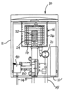
Referring now to Figs. 2 to 7, there will be
described a construction of the external gas-fired heater 10
of the present invention. As herein shown, a thermally
insulated combustion chamber 16 is secured in an upper
portion of the housing 11 and has a heating coil 17 mounted
therein. In this particular embodiment the heating coil is
comprised of two concentrically disposed spiral coils 17'
and 17" of heat conductive material, and which are serially
connected to one another, and have an inlet 18 and an outlet
19 through which a water/glycol mixture is circulated by a
pump 20. A temperature and pressure gauge 21 monitors the
glycol solution at the outlet of the coil.
A cylindric natural gas burner 22 is supported
concentrically at the center of the heating coil 17 and is
supplied a natural gas/air mixture by the mixing blower 23
to heat the spiral coil 17', 17", and hence the water/glycol
liquid solution circulated therethrough. Ideally, this
solution is a 50/50 mixture. Of course, other suitable
solutions may be used, but it has been found that the
particular glycol/water mixture provides for the mixture to
be operational from about -40 F to about 180 F making it
ideal for harsh northern climates. An ignitor 24 ignites
CA 02186803 2006-06-19
- 5 -
the cylindrical burner 22 and a flame is detected by a flame
detecting probe 25 mounted adjacent the burner 22. Controls for
these are provided on a control panel 45.
As better seen in Fig. 5, the combustion chamber 16 is
comprised of a thermally insulated cylindrical metal container 26
having a bottom wall and on which is disposed a bottom circular
refractory disc 27. A top refractory disc 28 is disposed over the
heating coil 17 to reduce heat loss from the container and to
increase the exchange efficiency of the heater. A top wall 29 is
secured over the top end 26' of the cylindrical container 26. The
refractory disc 28 is a solid disc to force the flue gas through
the heating coil spirals and up above the disc 28 periphery and
then through the evacuating port in the wall 29.
The flue gases which are convected through the port 29' is
directed into an exhaust duct which, as shown in Fig. 5, is
constituted by an intake pipe 30 which interconnects the port 29'
to an exhaust conduit 31 which extends through the housing 11 from
a top end to a bottom wall 11' of the housing. The outlet end 32
of the exhaust pipe 31 communicates the flue gases to atmosphere
through an orifice 33 provided in the bottom wall 11'. This
exhaust pipe 31 also pre-heats air within the housing to feed warm
air to the mixing blower 23 to increase the efficiency of the
combustion mixture thereof.
Fig. 6 illustrates an alternative embodiment of the exhaust
conduit for use in less cold climatic regions and, as herein
shown, it may be provided by an intake pipe 34 secured about the
port 29' of the top wall 29 of the combustion chamber, and having
diametrically opposed exhaust ducts 35 to release the combustion
products from the opposed sides of the top wall 13" of the cover
13. As herein shown, the top wall has notches 36 on opposed side
walls 37 thereof to accommodate the ducts 35.
As is better shown in Fig. 5, the various component parts of
the heater are individually removably secured
2186803
-6-
within the housing 11 by individual attachment brackets,
such as bracket 38 and quick connectors 39, to permit the
entire housing and its component parts and wiring to be
removed in a very short period of time for replacement
and/or for servicing elsewhere than on site if need be.
These quick connectors connect the gas pipes and heating
fluid pipes. As shown in Fig. 5, the gas pipe feeds a gas
valve 40 and an interchangeable orifice plate 41 regulates
the amount of gas which is fed to the blower 23 for
admixture with air. The gas supply and orifice plate are
connected to blower 23 by a orifice plate 41'. A pressure
control switch 42 and a temperature limiting probe 43 are
secured to the heated fluid pipes 15,15'. An air/gas
mixture control 47 is provided on the control panel 45, and
this control panel is mounted internally of the housing 11
and is accessible only to authorized personnel who have
access to the key lock 50.
As previously described and as better shown in Fig.
7, the housing 11 is a rectangular housing having an L-
shaped removably detachable cover 13. Lock means in the
form of a key operated lock cylinder 52 capable of actuating
a locking element 51, when a key is positioned and operated
in the key hole secures the cover 13 to the rectangular
housing 11. The front wall 13' of the cover 13, in a lower
inner section thereof, is provided with a spaced internal
metal wall 53 to form a narrow convection passage 54 to feed
air internally of said housing adjacent the top end of the
cover, as shown in Fig. 1. Access holes 56 are punched in
the bottom wall 11' of the housing to accommodate the
necessary piping and wiring.
The heater, as above described, has a heating
capacity of about from 30,000 to 200,000 Btu/h and is easily
adjustable by interchanging the orifice plate 41 to deliver
the required heat capacity within that range. The housing
11 is also mounted on an exterior wall of a building to
which the hot water/glycol solution is to be fed.
CA 02186803 2006-06-19
- 7 -
Fig. 8 shows a typical embodiment wherein the heater 10 is
mounted on the roof unit of a building. The feed line 15 of the
water/glycol solution is fed to a heat exchange device 60 located
inside the duct work 61 and through which air is circulated to
heat the air. An expansion tank 63, as is well known in the art is
connected the. line 15. A mixing valve 64 is also secured to the
fluid pipe 15 to prevent passage of cold water/glycol solution.
The hot glycol solution is circulated through the heat exchange
coil 60 where it cools and is then returned to the heating coil 17
through the return pipe 15'. As can be noted, the advantage of the
heater being mounted externally of the housing results in a saving
of space within the building and the air supply for the heater is
taken directly from the outside air. Accordingly, there is no
intrusion of air within the building by convection ducts.
Furthermore, the noise generated by the heater is located outside
the building and the gases are evacuated directly to the
atmosphere, thus avoiding the necessity of building a chimney.
Such a heater can also be utilized to replace existing electric
heaters by natural gas heaters. The heater is also easy to operate
and provides of ease of maintenance.
It has been found that the efficiency of the heater of this
invention is superior to 83% and that the NOX emission is inferior
to 30 ppm at 3% 02. The construction of the heater housing is also
aesthetically pleasing to the eye and provides added safety by
locking the heater components inside a housing which is accessible
to authorized persons only. Because the housing is wall-mounted,
such as on support brackets 11" as shown in Fig. 3, it can be
secured at a convenient height for maintenance and above the snow
line to provide ease of service in winter. The heater of the
present invention also results in a reduction in cost of operation
as compared to electricity. It also provides a more compact
housing than competitive heaters. It may also be used to heat
water or swimming
2186803
-8-
pools, radiant floors, radiators and a multitude of other
devices or may have other uses. It is pointed out that
tests have shown that the external gas-fired heater of the
present invention has a jacket heat loss of only about 2%.
It is also feasible to utilize the gas-fired heater for
applications in buildings having three rooms only or to
triplex-type buildings where there may be 15 to 20 rooms.
The units can also be fabricated in different sizes to
supply from about 30 to 200,000 Btu or from 40 to about
200,000 Btu.
It is within the ambit of the present invention to
cover any other obvious modifications of the example of the
preferred embodiment described herein, provided such
modifications fall within the scope of the appended claims.