Note: Descriptions are shown in the official language in which they were submitted.
217072
HANDRAIL AND BOMPER COMBINATION
Backaround and Summary of the Invention
In many types of buildings occupied and used by
significant numbers of people, it is common practice to
install handrails along the halls and corridors to assist
people in traversing these areas. Such facilities are
particularly useful and almost universally found in such
structures as hospitals, convalescent homes and the like.
In structures of the latter type, the passage ways are
traversed not only by people, but also by wheeled equipment
of various types. In these installations, it has become
common to employ combined handrail and bumper assemblies,
which are installed along the walls and provide a hand grip
for the convalescent and infirm, and also a means for
protecting the walls from being damaged by careless
handling of wheeled vehicles. Combination handrail-bumper
installations for this purpose are known and have been
commercially available. Examples of such previously
available unitary handrail-bumper systems of design are the
BR-300 and BR-800 handrails marketed by Pawling
Corporation, of Pawling, New York. These devices
incorporate an elongated, extruded aluminum support or
retainer over which is placed a semi-rigid plastic shell or
cover. The cover is contoured so that the upper portion
thereof forms a comfortable hand grip, while lower portions
provide a contact cushion against bumping by vehicles, etc.
Recent architectural preferences have indicated
a desire for handrail-bumper combinations to incorporate
handrail elements which can be of different colors than
other portions of the structure, or even of different
materials. For example it may be desirable to have the
handrail portion formed of a rigid vinyl shell, of the same
or different color than the associated bumper portion
below, or there may be a desire for the handrail portion to
CA 02187072 2001-09-28
2
be formed of wood. Additionally, there is an architectural
desire for accent strips, optionally of a different color,
joining a handrail portion along the top with a bumper
portion along the bottom. Particularly in institutional
structures, such as hospitals, the use of such accent strips
is desired to enable color coding of different areas of the
structure.
Early attempts to provide for design flexibility
in the choice of handrail materials and/or accent strips and
the like have been only partially satisfactory, because the
structures have tended to be relatively crude and angular.
Such arrangements are not only visually unattractive, but
are functionally disadvantageous. Flat, angular surfaces
are difficult to keep clean. In addition, surfaces that
present edges and corners can easily cause tears and
abrasions in the skin of elderly patients, who are the most
likely group of individuals to be utilizing the handrails
for support.
In accordance with a first broad aspect of the
present invention, there is provided a handrail-bumper
assembly, comprising:
(a) an elongated metal support of uniform cross
section adapted for mounting in spaced relation to
a wall,
(b) said support having a lower portion, an
intermediate portion, and an upper portion,
(c) a bumper cover member formed of rigid plastic
material and mounted on an outer face of said
support lower portion,
(d) said bumper cover member having an outwardly
convex upper wall curving upward an inward from a
generally vertical outer side wall thereof,
CA 02187072 2001-09-28
2a
(e) said support intermediate portion comprising an
outwardly concave web section integral with said
support lower portion and extending generally
$ upward therefrom,
(f) lower regions of said concave web section
extending upward and inward from an upper back
edge of said support lower portion,
(g) the contours of the lower regions of said concave
web section merging substantially tangentially
with the outwardly convex contours of the bumper
cover upper all,
(h) upper regions of said outwardly concave web
section extending upward and outward and
terminating at a point above and outward of said
lower regions of said web section,
(i) said support intermediate portion further
including an inwardly concave upper section,
integral with the upper regions of said concave
web section, merging tangentially therewith and
extending upward and inward therefrom,
(j) said support upper portion comprising a handrail
support of closed tubular configuration formed in
part by upper regions of said concave web section
and by said inwardly concave upper section
thereof,
(k) said support upper portion including wall segments
conforming to a closed curvilinear envelope,
(1) a hollow handrail cover, having curvilinear
interior contours conforming o said curvilinear
envelope, said handrail cover being open along
with a lower inner side and comprising an arcuate
upper wall portion and arcuate opposite side wall
portions,
CA 02187072 2001-09-28
2b
(m) said handrail cover being received over said
handrail support and being engaged and supported
by said wall segments,
(n) said handrail cover being formed of rigid plastic
$ material and having outer contours merging
tangentially with the inwardly concave upper
section, on the inside of said handrail, and the
upper regions of said outwardly concave web
section, on the outside of said handrail.
In accordance
with a second
broad aspect
of the present
invention, there is also provided a handrail-bumper
assembly, comprising:
(a) an elongated metal support of uniform cross
section adapted four mounting in spaced relation
to a wall,
(b) said support having a lower portion, an
intermediate portion, and an upper portion,
(c) a bumper cover member formed of rigid plastic
material and mounted on an outer face of said
support lower portion,
(d) said bumper cover member having an outwardly
convex upper wall curing upward and inward from
a
generally vertical outer side all thereof,
(e) said support intermediate portion comprising an
outwardly concave web section integral with said
support lower portion and extending generally
upward therefrom,
(f) lower regions of said concave web section
extending upward and inward from an upper back
edge of said support lower portion,
(g) the contours of the lower regions of said concave
web section merging substantially tangentially
with the outwardly convex contours of the bumper
cover upper wall,
CA 02187072 2001-09-28
ZC
(h) upper regions of said concave web section
extending upward and outward and terminating at a
point generally above said lower regions of said
web section,
(i) said support intermediate portion further
including an inwardly concave upper section,
integral with the upper regions of said concave
web section, merging tangentially therewith and
extending upward and inward therefrom,
(j) said support upper portion comprising a handrail
support of closed tubular configuration formed in
part by upper regions of said concave web section,
(k) said support upper portion including spaced apart
upwardly extending walls,
(1) a solid handrail, having curvilinear contours and
having a longitudinally extending, downwardly
opening recess of uniform cross section,
(m) said solid handrail being received over and
supported by the upwardly extending walls of said
support upper portion, with said upwardly
extending walls being received within said
downwardly opening recess,
(n) said handrail having outer contours merging
tangentially with the inwardly concave upper
section of said support intermediate portion, on
the inside of said handrail, and the upper
(portions) regions of said outwardly concave web
section, on the outside of said handrail.
In a handrail assembly of the type including an
elongated metal support member of uniform cross section, and
a generally solid handrail member of uniform cross section
supported on said metal support, the present invention also
provides, according to a third broad aspect, the improvement
characterized by
CA 02187072 2001-09-28
2d
(a) said handrail member having a downwardly opening
recess therein of uniform cross section extending
throughout the length of said member,
(b) said support member including a handrail support
adapted for reception in said downwardly opening
recess and having wall engageable with surfaces of
said recess for positioning said handrail with
respect to said support member,
(c) said handrail support including, as an element of
its uniform cross section, wall portions defining
a longitudinally extending alignment recess for
the snug reception of an alignment element,
(d) said assembly including at least two support
members and handrail members mounted in
longitudinally aligned relation, and
(e) an alignment element independent of said handrail
members snugly received in the alignment recesses
of the respective support members for accurate
alignment of the handrail supports thereof.
In accordance with a fourth broad aspect of
the present invention, a novel and improved handrail-bumper
combination assembly is provided which readily accommodates
the current architectural requirements of flexible design in
terms of materials, colors, etc. yet which also provides a
functionally superior structure with smooth, blending curved
surfaces free of sharp corners and the like, which are both
unsightly and likely to cause minor injuries to the fragile
skin of elderly patients. The basic conceptual design of
the invention is readily adaptable to handrails which are
formed of wood or are provided with a rigid vinyl cover, in
either case being provided with the facility to mount a
highly visible, yet evenly contoured accent strip.
In accordance with another aspect of the
~r
2187072
-3-
invention, novel and improved structural features are
provided for installing returns and corners for the
handrail-bumper combination. The arrangement of the
invention provides for greater strength and improved visual
appearance at corners and returns, as well as minimizing
the component parts required to construct both inside and
outside corners, for example.
For a more complete understanding of the above
and other features and advantages of the invention,
reference should be made to the following detailed
description of preferred embodiments of the invention and
to the accompanying drawings.
Description of the Drawing's
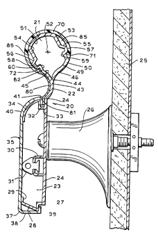
Fig. 1 is a cross sectional view of a preferred
form of handrail-bumper assembly constructed in accordance
with the invention.
Figs. 2 and 3 are side elevational and top plan
views respectively of a handrail-bumper installation of
Fig. 1, shown mounted at a corner of two walls.
Figs. 4 and 5 are a side elevational and top
plan view respectively of a lower or bumper portion of a
corner assembly incorporated in the installation of Figs.
2 and 3.
Figs. 6 and 7 are elevational and top plan views
respectively of a molded plastic intermediate member
forming part of the corner assembly.
Figs. 8 and 9 are top plan and side elevational
views respectively of an upper or handrail portion of the
corner assembly.
'''~ 2187072
-4-
Fig. 10 is a top plan view of a molded end cap
member, forming part of the corner structure, with related
parts, shown in cross section, illustrated in assembled
relation.
Fig. 11 is an end elevational view of the end
cap.member of Fig. 10.
Fig. 12 is a cross sectional view, similar to
Fig. 1, showing an alternative form of handrail-bumper
combination.
Fig. 13 is an enlarged, fragmentary view of a
portion of the structure of Fig. 12, illustrating details
of its construction.
Fig. 14 is a fragmentary elevational view,
illustrating an installation of the handrail-bumper of Fig.
12 with means for aligning successive sections thereof.
Description of Preferred Embodiments
Referring now to the drawings, and initially to
Figs. 1-3 thereof, the reference numeral 20 designates
generally a metal support or retainer, typically of
extruded aluminum, and of uniform cross section throughout.
The illustrated support has an upper or handrail support
upper portion 21, an intermediate portion 22, and a lower
or bumper support portion 23. The configuration of the
lower portion 23 is, in general, previously known.
However, as will be described, it is associated in a unique
and advantageous manner with the intermediate and upper
portions.
The lower portion 23 includes a generally flat,
2187072
-5-
vertically oriented back wall 24, by which the support can
be secured in spaced relation to a wall 25, using spaced-
apart stand-off supports 26, in a known manner. At its
lower end, the lower portion 23 is configured to provide a
lower retaining notch 27, an outwardly and upwardly
inclined displacement surface 28, and a short, vertically
extending support flange 29.
At an intermediate level, the lower portion 23
is provided with an integral, longitudinally extending
channel 30 arranged to receive and support a resilient
back-up strip 31, formed of suitably resilient material.
Near the upper edge of the lower portion 23, an
L-shaped integral flange 32 is provided, to form an upper
retaining notch 33. Extending integrally from the L-shaped
flange 32 is an outwardly convex support flange 34, which
extends outward and then downward from the upper edge of
the flange 32.
Pursuant to known constructions, the bumper
support portion 23 is arranged to receive and retain a
plastic cover 35, formed of extruded, rigid polyvinyl
chloride. The cover 35, which may be referred to as a
bumper cover, includes a generally flat, vertically
oriented front wall 36, which is supported at a midpoint by
the resilient backup strip 31. At its lower edge, the
cover has a rounded corner 37, a rearwardly extending
bottom wall 38 and a short upwardly extending retaining
flange 39. At its upper edge, the bumper cover is
outwardly convexly contoured, as at 40, to conform closely
with the convex contours of the support flange 34. A
short, downwardly extending retaining flange 41 is provided
along the inside edge of the arcuate wall 40.
2187072
-6-
After securing of the aluminum support 20 to the
stand-off supports 26, the bumper cover 35 is installed on
the support by inserting the upper retaining flange 41 into
the upper retaining recess 33, and then pressing inwardly
on the lower edge portions of the cover. The lower
retaining flange 39 is deflected downwardly by the flange
surface 28, until the retaining flange 39 is in a position
to snap into the lower retaining recess 27. The bumper
structure just described is, in general, a known and
reliable construction.
Extending upwardly and rearwardly from the upper
extremity 42 of the back wall 24 is a forwardly concave
arcuate web section 43 forming part of the intermediate
portion 22. At its lower edge of the web section 43 is
contoured to form a generally smooth, substantially
tangential transitional continuation of the contours of the
arcuate cover wall 4 0 and the underlying arcuate support
flange 34. As shown in Fig. 1, the intermediate web
portion 22 curves smoothly upward and then forward,
dividing at a midpoint 44 into outwardly and inwardly
extending arcuate web sections 45, 46, respectively. The
front web section 45 is contoured to form a continuation of
the arcuate contour of the web section 43 and terminates at
47, which can be considered the upper forward limit of the
intermediate portion 22.
The back arcuate web portion 46, which also
comprises part of the intermediate portion 22, is inwardly
concave, and merges tangentially in a smooth transition
with the inwardly convex curvatures of the web section 43.
The upper rear web section 46 can be considered as
terminating at about 49, where it merges tangentially with
the outwardly convex contours of a wall section 50, forming
part of the upper or handrail portion 21 of the support.
72
21 a7 0
In the structure of the invention, the handrail portion 21
is of a closed tubular configuration, when joined at 47 and
49 with the intermediate portion 22. An upper, outer
portion 51 is of outwardly convex contour, advantageously
forming an arcuate segment of a circle centered
approximately at the point designated at 52 in Fig. 1. The
arcuate portion 50 also preferably forms a surface segment
of the same circle.
Spaced-apart, preferably parallel walls 53, 54
extend angularly downward and inward from the opposite ends
of the arcuate segment 51 and join with outwardly angled
displacement surfaces 55, 56. Arcuate support surfaces 57,
58, and L-shaped notch-forming walls 59, 60 join with the
support surfaces 57, 58, and these last mentioned walls in
turn join with the arcuate wall segment 50 and the
intermediate web wall 45 to complete the closed tubular
configuration of the handrail support.
A handrail cover 70, formed of an extruded
plastic material, such as rigid polyvinyl chloride, is
arranged to be received over and supported by the handrail
support portion 21. In a preferred form of the invention,
the cover is an open-sided tube of circular contours,
formed at opposite ends with internal retaining flanges 71,
72 of generally triangular configuration arranged for
cooperation with retaining notches formed by the retaining
walls 59, 60. The handrail cover 70 may be installed by
applying the opposite edges thereof over the outer arcuate
portion 51 of the handrail support. The retaining flange
portions 71, 72 will slide along the walls 53, 54 and then
be displaced outwardly by the displacement surfaces 55, 56,
eventually allowing the retaining flanges 71, 72 to snap
into the retaining recesses formed by the L-shaped
retaining walls 59, 60.
2187072
_8_
In the illustrated form of the invention, an
elongated, thin accent strip 80 of outwardly concave
contour, is supported in close fitting relation on the
outer surface of the concave walls formed by the
intermediate web sections 45, 43. A first retaining flange
81, provided along the lower edge of the accent strip, is
arranged to be received in the retaining notch 33, between
the flange 41 of the bumper shell and the back wall 24. A
retaining flange 82, provided along the upper edge of the
accent strip, is arranged to be closely received between
the front retaining flange 72 of the handrail cover and the
L-shaped retaining wall 60. Thus, as shown in Fig. 1, a
combination of the circularly configured handrail cover 70,
and the similarly configured arcuate portion 50 of the
handrail support, provide for the handrail configurations
to be uninterrupted, substantially circular configuration,
from the tip of the front retaining flange 72 to the point
49 at which the arcuate wall 50 merges with the
intermediate web wall 46. The arrangement provides for a
sturdy, smooth gripping portion, extending over a large
fraction of a complete circle, for example as much as 300°.
Additionally and equally important, the adjacent touchable
surfaces of the cover 70 and its support merge in smooth
transition from the convex circular contours of the upper
handrail portion to the concave contours of the upper
intermediate portion 46 in the back, and the concave accent
strip 80, in the front. The concave contours of the accent
strip also merge in a smooth, substantially tangential
transition with the convex upper wall of the bumper shell.
This configuration is advantageous in that it minimizes
dirt collection, facilitates cleaning and also tends to
make the accent strip 80 more readily visible. This is of
considerable utility in many institutional buildings, where
it is desired to provide color coding by means of the
2187072
-9-
accent strip for easier identification of particular areas
of the structure.
As shown in Figs. 2 and 3, a typical handrail-
bumper assembly comprises straight sections 90 mounted
along a wall 25 by means of the supports 26. At an outside
corner, a special corner assembly 91 is provided to j oin
adjacent, angularly related straight sections 90. While
Fig. 3 illustrates an "outside" corner, it will be
understood that a similar corner assembly (not shown) is
needed for connecting adjacent straight sections at an
"inside" corner. The outside corner assemblies can also be
used, with minor modification as will appear, to construct
"return", providing a transition from an exposed end of a
handrail section on a given wall over to an adjacent
section of the same wall. The handrail-bumper assembly of
the invention includes an advantageous form of
corner/return assembly which, insofar as practicable,
retains the advantageous utilitarian features of the basic
(straight) assembly, as well as the visually pleasing
features thereof. At the same time, the assembly is easy
to install and forms a sturdy element of the handrail-
bumper system.
An advantageous corner assembly includes a
bumper section, shown in Figs. 4 and 5, an intermediate
section, shown in Figs. 6 and 7, a handrail cap (Figs. 8-
10) and a handrail member (Figs. 11, 12).
While elements of the straight handrail-bumper
sections advantageously are extruded, the corner/return
sections, being of arcuate contour, are necessarily molded.
And because of the complexity of the multiple contours, it
is more economical to construct an assembly of several
molded components, than to attempt to produce a complex,
2181072
-10-
one-piece molding.
In Figs. 4 and 5, there is shown an advantageous
form of molding for the bumper portion of an outside
corner. The bumper portion 100 is a solid molding of rigid
plastic having a front surface 101 formed with contours
corresponding substantially to the outer surface contours
36-40 of the bumper cover 35. Inset slightly from the
outer surface 101 is a first projecting flange 102, forming
an abutment flange, and this flange has contours closely
conforming to the front contours of the bumper support
portion 23. In this respect, an outwardly convex upper
flange portion 103 conforms substantially to the contours
of the support flange 34, and a leg 104, which projects
downwardly from the upper edge of the flange portion 103
conforms to the vertical leg of the L-shaped retaining
flange 32. An upwardly and outwardly inclined flange
portion 105 at the bottom corresponds to the displacement
flange 28, and the L-shaped portions 106 correspond to the
L-shaped sections defining the lower retention notch 27.
A vertically extending flange portion 107 connects the
upper and lower flange portions 103, 105. A rear flange
portion 108 corresponds in location to the vertical back
wall 24 of the aluminum support portion 23.
Second and third projecting flanges 109, 110 are
provided adjacent the top and bottom respectively. These
flanges are shaped to conform respectively to the internal
contours of the metal support portion 23, at the top and
bottom portions. As shown in Fig. 5, the flange portions
109, 110, which may be referred to as positioning flanges,
project from the body of the corner piece well beyond the
ends of the abutment flanges 103-108. Fastening tabs 111,
112 also project from the end of the member 100, in a
position to lie against the inside surface of the support
2187072
back wall 24, preferably projecting well beyond the ends of
the positioning flanges 109, 110.
As reflected in Figs. 4 and 5, the various
flanges and projections described above are provided at
both ends of the bumper corner member 100, accommodating
attachment of a straight section of handrail-bumper at each
end.
A bumper corner member 100 is attached to a
previously installed support member 20 prior to
installation of the bumper shell 35, by inserting the
positioning flanges 109, 110 and the mounting tabs 111, 112
into an open end of the metal support. The positioning
flanges 109, 110 make snug contact with the internal
contours of the support to accurately align the corner
member 100. The corner member is inserted until the
squared-off end of the support 20 makes contact with the
various abutment flange surfaces 102-106. The member 100
can then be secured to the support by suitable bolts or the
like (not shown) located in openings 113 provided in the
mounting tabs 111, 112.
To advantage, the various abutment elements 102-
107 project a short distance (for example, 1/4 inch) from
the end surface 101, which defines the end of the main
portion of the bumper member 100, which is contoured to
correspond to the outer surface contours of the plastic
outer shell 35. In addition, these abutment projections
have external contours which are very slightly (e. g., 0.015
inch) larger than the external contours of the metal
support member 20. The plastic cover 35, as shown in Fig.
5, is cut to a length correspondingly longer at each end
than the metal support 20, so that the cover extends over
the outside of the abutment projections 102-107 and abuts
2187072
-12-
with the end surface 101. By providing for the external
contours of the abutment projections 102-107 to be slightly
larger than the nominal external dimensions of the metal
support, it is assured that, at the end extremities of the
cover 35, its support and positioning will be determined by
the contours of the molded-in abutment projections, so that
more precise alignment between the external surfaces of the
shell 35 and the external surfaces of the bumper corner
element 100 is assured. This provides for a much neater
looking joint at the corner, and also one that is less
likely to snag or abrade delicate skin of an elderly
patient.
As indicated in Fig. 5, the main body portion of
the bumper member 100, between the respective end surfaces
101, covers an arc of 90°. The various flanges and other
extending portions project in a straight line from the end
faces 101, for insertion in supports 20 mounted on adjacent
walls disposed at 90°. Where the corner assembly is to be
employed as a return, i. e. , where the corner assembly is
inserted at one end into the end of a handrail support, and
the corner assembly then curves into and abuts with the
surface of the same wall, all of the projecting flanges and
mounting tabs at the wall end are removed, so that the end
face 101 can be positioned in confronting relation to the
wall surface.
In the illustrated structure, the bumper corner
member 100 would not customarily be installed as an
individual component, but as an assembly of components
constituting a bumper section, an intermediate section and
a handrail section. This assembly is customarily made at
the factory, so that the field installer deals only with
the completed corner assembly. In the illustrated form of
the invention, the intermediate element is shown in Figs.
~~~7072
-13-
6 and 7 of the drawing, and the handrail section, shown in
Figs. 8 and 9 of the drawing, and an end cap element is
shown in Figs. 10 and 11 of the drawing.
With reference now to Figs. 6 and 7, the
intermediate corner section 200 comprises a downwardly
projecting mounting flange 201 arranged to be mounted on an
arcuate upper back wall 115 of the bumper portion 100,
directly above the back wall portion 108. This can be
assembled by mechanical fasteners, such as sheet metal
screws, by adhesives or other means. The intermediate
portion has a main body extending over an arc of 90°, and
has short, straight extending portions 202 at each end
which will, in the assembled corner, interfit with an end
cap member, to be described.
The body portion of the intermediate member
includes a pair of vertically extending, radially spaced
arcuate flanges 203, 204 which terminate at vertical end
flanges 205. The latter are drilled at 206 to receive
fastening devices, as will be described. The outer end
faces 207 of the vertical end flanges 205 are oriented at
90° and define the opposite ends of the main body of the
intermediate section 200.
Joining the mounting flange 201 with the upper
flanges 203, 204 is an outwardly concave flange 208, which
corresponds generally in its contours to those of the
intermediate portion 22 of the primary metal support 20.
In this respect, the arcuate flange 208 divides at 209 into
front and back portions 210, 211 corresponding generally in
contours to the flange portions 46, 47 of the metal support
(see Fig. 1). The front flange portion 210 terminates at
the outer surface of the vertical flange 203, while the
back flange portion 211 projects slightly beyond the inner
2187072
-14-
walls of the flange 204, to form an upwardly facing support
surface 212.
As reflected in Fig. 6, the outwardly concave
flange portions 208, 210 are recessed slightly in the
region of the outer extensions 202. The short recess,
indicated by the reference numeral 213 in Fig. 6, provides
for the reception of a short projecting end portion of the
accent strip 80. Over the 90° arcuate portion of the
element 200, the outer surface 214 of the concave flange is
dimensioned to be substantially flush with the outer
surface of the accent strip 80 where the strip abuts with
an end surface 215 (Fig. 6). In the short projecting
regions 202, the upper end of the concave flange portion
210 joins with a short flange portion 216 (Fig. 6)
extending upward at an angle in general correspondence with
the lower leg of the L-shaped, notch-forming flange 60 of
the handrail portion 21 of the metal support.
A handrail portion of the corner assembly is
indicated by the reference numeral 300 in Figs. 8 and 9.
The element is of generally circular cross section,
extending over an arc of 90°, and is formed of a molded
plastic material, such as polyvinyl chloride. The
dimensions of the circular cross section are substantially
identical to those of the handrail cover 70, so that the
handrail portion of the corner assembly forms a
continuation of the surface contours of the handrail cover.
At each end, the handrail section is formed with
a flat end surface 301 and a central recess 302, which can
be mostly of circular contours, but has at least some non-
3o circular portion 303 for alignment purposes. Along its
bottom, the handrail element 300 is formed with a
downwardly opening arcuate recess 304 of a size and shape
2187072
-15-
to closely and snugly receive the arcuate flanges 203, 204
of the intermediate member. In the final assembly, the
handrail element 300 is secured to the intermediate member
by mechanical fasteners and/or adhesives.
Prior to assembly of the handrail element 300
with the intermediate element 200, end cap elements 400,
shown in Figs. 10 and 11, are mounted at the opposite ends
of the handrail element. The end cap element 400 is a
precision molded part, formed of a material such as
polyvinyl chloride and is formed at one end with a
projecting boss 401, the size and shape of which are such
as to be snugly received in a recess 302 of the handrail
element. Internally, the end cap member has a vertical
slot 402 of a size and shape to closely receive the end
flanges 205 of the intermediate element. Thus, in
assembling a corner unit, the end cap members 400 are
assembled with the handrail portion 300, by inserting the
projecting bosses 401 into the recesses 302. The end caps
are rotationally oriented by reason of the non-circular
cross sections of the bosses 401 and recesses 302, as will
be understood. When the end caps are assembled, the
recesses 402 therein are oriented to open vertically
downward, allowing the assembled handrail and end caps to
be joined together with the intermediate element 200, with
the end flanges 205 being received in the recesses 402 and
the flanges 203, 204 being received in the arcuate recess
304 of the handrail element. The intermediate and handrail
portions 200, 300, and the end caps 400, can all be secured
in a tight permanent assembly by screws installed at each
end, entering through the flange openings 206, passing
through openings 403 in the end cap elements and being
threadedly received in bored recesses 305 in the handrail
portions. At this stage of assembly, the just-described
subassembly may be joined with the lower bumper unit, by
2187072
-16-
attaching the flange 201 of the intermediate member to the
back surface portions 115 of the bumper portion.
It will be understood that the end cap elements
400 are molded for left-hand and right-hand installation
such that, when inserted in opposite ends of a handrail
element 300, the tilt of the contours will be upward and
outward in both cases.
As reflected in Figs. 10 and 11, the end cap
members include an axially projecting flange 404,
consisting of upper and lower arcuate portions 405, 406 and
spaced-apart, parallel side flange portions 407, 408. The
external contours of the flanges 404-408 are such as to
generally conform to and be snugly received within the
interior of the hollow tubular hand rail support portion
21. The end cap member is also provided with an
intermediate portion 410 conforming closely in size and
shape to the external contours of the upper portions of the
tubular handrail portion 21 of the metal support. Thus,
when the projecting flanges 404 of the end cap are inserted
axially into the open end of the metal handrail portion 21,
the contours of the intermediate collar flange 410 form
essentially a continuation of the surface contours of the
metal handrail portion 21. Advantageously, however, the
dimensions of the end cap intermediate collar flange 410
are just slightly greater (e. g., 0.010-0.015 of an inch),
so that the surface line of the overlying handrail shell 70
is more precisely controlled by the molded outer surfaces
of the intermediate collar flange 410.
As reflected particularly in Fig. 11, the lower
portions of the intermediate collar flange 410 merge with
the upper flange portions 210, 211 and 216 of the
projecting end portions 202 of the intermediate member, so
that the collar flange 410 and the projecting portions 202
2187072
of the intermediate member provide a full continuation of
the outer contours of the metal support 20.
A complete corner assembly forms a rigid unit of
a bumper portion 100, an intermediate portion 200, an upper
or handrail portion 300 and end caps 400 at opposite ends.
This assembled corner unit is installed on to the end of a
handrail support 20, prior to installation of the shell
cover 70 and bumper cover 35, and also prior to the
installation of the accent strip 80. All of the last
mentioned elements are cut to length slightly longer than
the metal support 20 (e. g. 1/4 inch at each end), so that
each of the elements 35, 70, 80 has an end extremity
supported by elements of the corner structure which are
just slightly larger in dimension than the corresponding
dimensions of the metal support, assuring a high level of
precision in the surface alignment of corner assemblies
with corresponding surfaces of the straight elements.
Assembly of the corner is performed by inserting
the projecting flanges 404 of the end cap into the upper
portion 21 of the metal support while the alignment flanges
109, 110 of the bumper member 100 are inserted into the
lower or bumper portion 23 of the metal support. The
assembly is then fixed to the metal support by mechanical
fasteners, to attach the mounting tabs 111, 112 to the back
wall of the metal support. If desired, for additional
strength and support, one or more sheet metal screws, pop
rivets or the like may be used to fasten the projecting
flanges 404 of the end caps to the end portions of the
handrail supports 21. Where such means is employed, it is
convenient to install the mechanical fastening means in one
or both of the clearance areas 85 (Fig. 1) between the
handrail cover 70 and the side flanges 53, 54 of the metal
handrail support 21.
2187072
The described corner assembly is easily
installed and provides a rugged joint between the corner
assembly and the primary handrail-bumper unit. In the
past, these joints have tended to represent a weak point in
the handrail installation. Additionally, where the corner
assembly is employed as a return to the wall surface, the
recess 302 facing the wall provides an area for a hidden
mechanical support at the wall end of the installation, so
that weight applied to the corner unit adjacent to the wall
does not apply torque to the principal handrail structure.
It will be understood, of course, that, when the corner
unit is employed as a return to the wall, all of the
projecting portions 202 of the intermediate element 200,
and all of the projecting flanges and tabs of the bumper
portion 100 (at the wall end only in both cases) are
removed.
The illustrated components are shown for the
assembly of an "outside" corner, as shown in Fig. 3 of the
drawings. For the formation of an "inside" corner, the
illustrated design permits the interchangeable use of the
handrail elements 300 and the end caps 400. However,
separate molds are required for the bumper portions 100 and
intermediate portions 200 so that the outwardly facing
contours are properly oriented in the molded parts. The
interchangeable use of the handrail and end cap elements,
however, results in considerable savings and mold costs.
An alternative embodiment of the invention,
shown in Figs. 12-14, is designed for the installation of
a wood handrail portion, in association with a bumper and
accent strip arrangement substantially as described with
respect to the embodiment of Figs. 1-11.
2187072
-19-
In Fig. 13, there is shown details of the upper
assembly of the alternative embodiment, it being understood
that portions of the unit below that shown in Fig. 13 can
be of the same general construction as previously
described. In the alternative embodiment, a tubular upper
support portion 500 is defined by generally vertical front
and back walls 501, 502 and an arcuate top wall 503. The
front and back side walls are deeply serrated, as at 504 to
receive an adhesive material. An elongated wooden handrail
portion 505, formed with a downwardly opening vertical slot
506, is closely received over the walls of the support
portion 500. A lower back edge 507 of the wooden handrail
engages and is supported by a rearwardly projecting flange
508 formed by a rearwardly concave flange portion 509. The
latter is formed integrally with the forwardly concave,
accent strip receiving flange 510 of an intermediate
portion 511 of the metal support. As shown particularly in
Fig. 13, the rearwardly concave surface portions 509 curve
progressively rearward and merge substantially tangentially
with the circular external surfaces 512 of the hand grip
505.
The front side wall 510 of the handrail support
has a recess 513 for the reception of a retaining flange
portion 514 of an accent strip 515. The upper retaining
flange 514 is captured between the front wall 501 and the
inside front wall portion 516 of the handrail recess 506.
In the installation of so-called wood-over-vinyl
or wood-over-wood handrail-bumper assemblies, the proper
alignment of successive sections of the wood handrail is a
nagging problem. Heretofore, one of the common practices
has required the field installation personnel to drill
alignment holes in adjacent handrail sections for insertion
1
2187072
-20-
of an alignment dowel. This cannot be done effectively at
the factory, because the exact length of the handrail
section in a particular installation may not be known. In
the system of the applicant's invention, however, the upper
handrail support 500 is provided at a point, typically
constituting the center of an installed handrail section,
with a continuously extruded, generally circular recess
517, arranged to receive an alignment dowel 518 (Figs.
13,14). In this manner, two successive handrail support
sections are precisely aligned, regardless of length,
because the dowel-receiving recess runs continuously
throughout the length of the support. Accurate alignment
of the successive supports is thus assured. Accurate
alignment of the handrail portions 505 themselves is
achieved by accurate machining of the recess 506, so that
the closed end surface 518 of the recess is in a known and
consistent location. A flat support surface 519 is formed
at the top of the support surface 503, enabling the
handrail 505 to be firmly and accurately seated on the
support 500. This accurate seating is retained by use of
suitable adhesive on the internal surfaces or, if
preferred, mechanical fastening means. Preferably, the
wood employed for the handrails 505 is kiln dried prior to
installation, to avoid tendencies for later warpage, etc.
In either of its illustrated forms, the
handrail-bumper assembly of the invention provides a
particularly advantageous handrail mounting and support,
with tangentially merging smooth arcuate contours front and
back providing an unusually comfortable hand grip facility,
which both feels good to the touch and is substantially
free of recesses and edges, which are irritating sources of
discomfort and, in cases, minor injury.
In the embodiment of Figs. 1-11, an especially
2187072
-21-
advantageous form of plastic handrail structure is
provided, which includes a generally closed tubular upper
support formed with a large area, outwardly and upwardly
facing arcuate support surface for an extruded plastic
handrail cover. In addition, the support is provided with
flanges forming L-shaped retaining recesses, for capturing
generally triangular internal retaining flanges at each
edge of the handrail cover. The structure enables the
retaining flange portions of the cover to taper to an edge,
merging smoothly into continuing arcuate surfaces along the
underside of the handrail support. The arrangement
provided is not only aesthetically superior in significant
ways, but is also functionally superior in reducing to a
minimum angular surfaces which, even if concealed on the
back of the handrail, are detectable by feel by users of
the handrail and are the source of annoyance, discomfort,
and possible minor injury.
The described system is provided with a new and
advantageous form of corner or return assembly, which
provides an unusually strong joint and which, by reason of
its construction, provides a significantly neater and
functionally superior corner joint.
It should be understood, of course, that the
specific forms of the invention herein illustrated and
described are intended to be representative only, as
certain changes may be made therein without departing from
the clear teachings of the disclosure. Accordingly,
reference should be made to the following appended claims
in determining the full scope of the invention.