Note: Descriptions are shown in the official language in which they were submitted.
WO 95130373 I~ t
~1 88668
METHOD AND APPARATUS FOR CONTROLLED
CONTRACTION OF SOFT TISSUE
R~CKGROUNn OF TEIF ~l~VENTION
Fif l.l of th.~ Inventi.~n
This rnvention relates generally to the contraction of soft tissue, and
more ~ ' 'y, to the . , of soft collagen tissue with minimal
.,. of collagen tissue.
10 l~Perr~tinn ofthe l~l ' ' Art
Instabilit~v of peripheral joints has long been recognized as a sigmficant
cause of disability and functional limitation in patients who are active m theirdaily activities, work or sports. Diarthrodial joimts of ' ' ' ' system
have varying degrees of intrinsic stability based on joint geometry and ligamentand soft tissue investment. Diathrodial jomts are comprised of the ~rtir~ til~n
of the ends of bones and their covering of hyaline cartilage surrounded by a soft
tissue joint capsule that maintains the constant contact of the cartilage surfaces.
T_is joint capsule also maintains within the joint the synovial fluid that provides
nutrition and lubrication of the joint surfaces. Ligaments are soft tissue
~. ,.. l.. ~ .1.. ~ in or aroumd the joint capsule that reinforce and hold the joint
together while also controlling and restrictmg various I~ . of the joints.
The ligaments, joint capsule, and connective tissue are largely comprised of
collagen.
When a jomt becomes unstable, its soft tissue or bony structures allow
for excessive motion of the joint surfaces relative to each other and in directions
not norrnally permitted by the ligaments or capsule. When one surface of a jomt
slides out of position relative to the other surface, but some contact remains,
s 1 ,~ occurs. When one surface of the joint completely disengages and
loses contact with the opposing surface, a dislocation occurs. Typically, the
30 more motion a joint normally r'---- tbe more inherently loose the soft
I
W0 95/30373 1 ~1/~ 7
21 886~8
tissue investment is aulluul~ g the joint. This makes some joints more prone
to instability than others. The shoulder, (,,' - ' ') joint, for example, has
the greatest range of motion of all peripheral jomts. It has long been recognized
as having the highest Y~ . and dislocation rate because of its inherent
S laxity relative to more, ' "ball and socket" joints such as the hip.
Instability of the shoulder can occur congenitally, d~ v~ Y, or
tr.DIl~otir~lly and often becomes recurrent, ,.- - ~ surgical repair. In fact
,"1,11. . .l ;. " ,~ and ~ ;.."c are a common occulrence and cause for a large
number of orthopedic procedures each year. Symptoms include pain,
instability, weakness, amd limitation of function. If the instability is severe amd
recurrent, functional incapacity and arthritis may result. Surgical attempts aredirected toward tightening the soft tissue restraints that have become
,A1l,r.1.~ 11y loose. These procedures are typically performed through open
surgical approaches that often require 11~ A1 ;1~11 and prolonged
rPhDhilitDtirn programs.
More recently, endoscopic (alLLual~olJ;c) techniques for achievmg these
same goals have been explored with variable success. Fn~ir~c~r~pir techniques
have the advantage of being performed through smaller incisions amd therefore
are usually less painful, performed on an outpatient basis, are associated with
less blood loss and lower risk of infection and have a more cualll~ lly
acceptable scar. Recovery is often faster puaLu~ iv~ly than using open
tec_niques. However, it is often more technically demanding to advance amd
tighten capsule or l;L,r "- ~ tissue .uLhua~u~ ally because of the difflcult
access to l, ~ rl~ lly loose tissue amd because it is very hard to determine
how much tightening or ad~Lul.,. lll~lL of the lax tissue is clinically necessary.
In addition, fixation of advanced or tightened soft tissue is more difficult
cu Lllluacu~ lly than through open surgical methods.
Collagen commective tissue is ubiquitous in the humam body and
~--- several unique . l . -, ~ t ;~ not foumd in oth-er tissues. It
provides the u ~h~ a;~ of the mllcrll I cl~ tDl system, the structural integrity
wo ss/30373 ~ s~3z
~1 88668
of the viscera as well as the elasticity of int~gl.m~-nt These are basically five
types of collagen molecules with Type I being most common in bone, tendon,
skin amd other connective tissues, and Type III is common in muscular amd
elastic tissues.
1.. ,.. ~ cross links provide collagen connective tissue with
unique physical properties of high tensile strength and substantial elasticity. A
previously recognized property of collagen is ll, ~LULII~ Illlal shrinkage of
collagen fibers when elevated in L'~ ,l.liLUC:. This unique molecular response
to ~ Lul~ elevation is the result of rupture of the collagen stabilizing cross
links and immediate contraction of the collagen fibes to about one-third of their
original lineal distention. Additionally, the caliber of the individual fibes
increases greatly, over four fold, without changing the structural integrity of the
connection tissue.
There has been discussion in the existmg literature regarding alteration
of collagen connective tissue in different parts of the body. One known
technique for effective use of this knowledge of the properties of collagen is
through the use of infrared laser energy to effect tissue heating. The use of
infrared laser energy as a corn~al collagen shrinking tool of the eye has been
described and relates to laser I ,' :y, as set forth in U.S. Patent No.
4,976,709. The importance controlling the il')l`.'li751ti(~\n, timing and intensity of
laser energy delivery is recognized as paramount in providing the desired soft
tissue shrinkage effects without creating excessive damage to the ~IIIUIIIl~l'LUg
non-target tissues.
.. r, c l.. ~ (RF) electrical current has been used to reshape the
comea. Such shaping has been reported by Doss in U.S. Patents No. 4,326,529;
and 4.381,007. However, Doss was not concerned with ~ ..g collagen
tissue in his reshaping of the cornea.
Shrinkage of collagen tissue is import~mt in many .~ lC One
such application is the shoulder capsule. The capsule of the shoulder consists of
a synovial lining and three well defined layers of collagen. The fibers of the
W0 95/303~3 P.~
21 88668
inner and outer layers extend in a coronal access from the glenoid to the
humerus. The middle layer of the collagen extends in a sagittal direction,
crossing the fibers of the other t~vo layers. The relative thickness and degree of
~" ~ of collagen fibers of the three layers vary with different portions
S of the capsule. The l;~ c.. ~ " of the capsule are ~ t~,~ by
abrupt 11 - .L ~ of the inner layer with a significant increase in well
organized coarse collagen bundles in the coronal plane.
The capsule functions as a hamunock-like sling to support the humeral
head. In pathologic states of reculrent traumatic or .1., v ~,IU~ IL.I instability
this capsule or pouch becomes attenuated and the capsule capacity increases
secondary to capsule .~.lu lJal.~,~. In cases of congenital or d., ~,lv~
multi-directional laxity, an altered ratio of type I to type III collagen fibers may
be noted. In these shoulder capsules a higher ratio of more elastic type 111
collagen has been described.
There is a need for a method and apparatus to effect controlled lineal
contraction or shrinkage of collagen fibers to provide a multitude of non-
destructive amd beneficial structural changes and corrections within the body.
More p~ ,ul~uly with regard to the shoulder capsule, current surgical
techniques involve cutting or advancing the shoulder capsule to elimmate
capsular Ici.lUIl.l~l.,C or to otherwise tighten the ligamous complex.
Accordingly, there is a need to control shrinkage of the capsule by utilizing the
knowledge of the properties of collagen in response to a specific level of
thermal ~rrli--~tinn
SUMMARY OF THI~ INVENTION
It is an object of the present invention to provide a method and apparatus
to control the duration and application of thermal energy to a tissue site made
that includes collagen soft tissue; a desired level of contraction of collagen
fibers is obtained while 11icco~ i ~tinn and breakdown ofthe collagen fibers is
minimized.
WO 9S/30373 I ~ S~S32
~ 21 8~668
Another object of the present invention is to use RF heating in a fluid
vil Ulllll~ to control themmal spread to a tissue that mcludes collagen soft
tissue, and a desired contraction of collagen fibers is obtained while ., .
~;;CQ~ t;O11 and breakdo vn of the collagen fibers.
Yet another object of the present inYention is to provide a device
directed to collagen connective tissue shrinkage by the use of RF heating to a
tl,~llu~,lall ci profile of 43 to 90 degrees centigrade.
Another object of the present invention is to provide a device directed to
collagen conmective tissue shrinkage by the use of RF heating to a t~,...,t,~,...~..
profile of 43 to 75 degrees a,ontri~l,o
Still a further object of the present invention is to provide a device
directed to collagen connective tissue shrinkage by the use of the RF heating toa t~,lllu~,la~ profile of 45 to 60 degrees centigrade.
Another object of the present invention is to provide an apparatus which
delivers RF energy through an nl~ y guided handpiece in a fluid
ellv;lullllll,lll to obtain maximum contraction of collagen soft tissue while
",;";",;,;"~ ;..., and breakdo~n ofthe collagen tissue.
Yet another object of the present invention is to provide an apparatus
tbat provides for the maximum amount of collagen contraction without
.1~ 1;.. " of the collagen structure.
Anotber object of the present invention is to provide an apparatus to
deliver a controlled amount of RF energy to the collagen soft tissue of a joint in
order to contract and restrict the soft tissue elasticity and improve joint stability.
A further object of the present invention to provide an apparatus and
method tbat reduces ~du~do~ of the shoulder capsule and improves stability
to the joint.
These and other objects of the invention are obtained with an apparatus
for control contraction of tissue that includes collagen fibers. The apparatus
include a handpiece, and an electrode with an electrode proximal end that is
3~ associAted ith a~e h ~ dplece ~ distsl ~nd o~the electr~de has A geOlnetly tbllt
WO 95/30373 r~ ?
~1 886~8
delivers a controlled amount of energy to the tissue irl order to achieve a desired
contraction of the collagen fibers. This is achieved while .1;~ and
breakdown of the collagen fibers is minimized.
The handpiece, with electrode, is adapted to be introduced through ar
S operating camlula in ~ Additionally, it may be
desirable to include as part of the apparatus an operating calmula. In this
instance, the operating cannula has a proximal end that attaches to the
handpiece, and a distal end that is adapted to be introduced into a body
structure. lAhe electrode is positioned within the operating calmula, and
extendable beyond the distal end of the cannula when thermal energy is
delivered to the tissue
It is recognized that the delivery of the thermal energy to the tissue
should be delivered in such a way that none of the tissue is ablated
Additionally, the delivery is achieved without .1; . ---- ~ or breaking down thecollagen structure. IAhis can be A~ in different ways, but it has been
discovered that an electrode with radiused edges at its distal end is suitable to
obtain this result. lAhe present invention is applicable to a number of different
anatomical sites. Depending on the anatomy, it may be necessary to deflect the
distal end of the electrode to reach the desired site. Additionally, one side of the
electrode may include an insulating layer so that thermal energy is only
delivered to the intended tissue, and not a tissue in an adjacent ,.1.~;. ,,,~1,;1, to
the area of treatment.
In certain instances it is desirable to be able to vary the length of the
electrode conductive surface which delivers the thermal energy to the tissue.
For this purpose, an adjustable insulator, that is capable of movement along theIA,nLjr~ axis of the electrode, provides a way of adjustirlg the length of
electrode conductive surface.
Memory metals can be used for the electrode CUII~II U liUII. An
advantage of memory metals is that with the application of heat to the metal, it
woss/30373 2~ 88668 I_~IL ~ S~7
c~m be caused to be deflected. This is ~ ulafly useful for deflecting the distalend of the electrode.
The electrode can mclude a central lumen that receives am electrolytic
- solution from an electrolytic source. A plurality of aperLures are formed in the
S distal end of the electrode and deliver the flowing electrolytic fluid to the tissue.
Instead of an electrolytic solution, am electrolytic gel can also be introduced
through the electrode.
In one r ~ o~ 1 of the invention, the electrode is partially surroumded
by an insulating housing in order to position the electrode in am adjacent but
spaced rPlti~ ~ . to the tissue. A portion of the insulating housing rides on
the tissue, amd creates the equivalent of a paltial dam for electrolytic solution
introduced through the electrode and towards the tissue. A cuffis disposed
about the insulating housing. The cuff and insulating housing together create a
return electrolytic solution channel for the removal of solution flowing out of
the dam and away from the tissue site.
The handpiece of the invention can be connected, with a cable, to am RF
energy source. A closed loop feedback system can be included and coupled to a
~ ILUUC; sensor on the electrode and the RF energy source. Temperature at
the electrode can be monitored, and the power of the RF energy source adjusted
to control the amoumt of energy that is delivered to the tissue.
The present invention has wide spread application to many different
amatomical locations. It can be utilized for controlled contraction of collagen
softtissueofajointcapsule,~li.,,ll~ulythegleno-humoral jointcapsuleofthe
shoulder, to treat herniated discs, the meniscus of the knee, for d~ Lulu~, to
r~ame just a few.
In one .",.I~...li..,..11 of the invention, RF heating in a fluid or saline
~IIV;IUIUII~,I. is used to control thermal spread to sofl collagen tissue. The RF
energy c m be delivered through an ~ u~ ly guided h~mdpiece urlder
~uLIuu:~u~;~ viC~ tinn by the surgeon. In the L~ lll,u~ Lu~ range of 43 to 90
deere~ C, ma~d~um collsgen coD~cd~n is . hleved ~dddtio d 1.. ~ .. ~.
w095/30373 21 ~668 ~ 432
ranges are 43 to 75 degrees C, and 45 to 60 degrees C. Lower ~.~ u..,., do
not provide maximum therrnal induced contracture of the collagen fibrils.
Greater i -r ' CD create excessive destruction and .1;~;,. . ~,.,.l;..., ofthe
collagen fibrillar pattern. Thus, the present invention is a method and apparatus
S which accurately controls the application of heat within a desired thermal range.
This heat is delivered the collagen soft tissue, thereby contracting and restricting
the soft tissue elasticity and improving stability.
DESCRIPTION OF THE DRAWINGS
Figure I isa~ Livcplanviewofanapparatusforcontrol
contraction of tissue that includes collagen fibers, including a handpiece and an
electrode, according to the invention.
Figure 2 is a perspective plan view of a distal end of the electrode with
all edges radiused according to the invention.
Figure 3 is a side view of the distal end of the electrode of Figure 2.
Figure 4 is a sectional view of the deflected electrode with a resistive
heating element positioned in an interior lumen of the electrode according to the
invention.
Figure 5 is a perspective plan view of the apparatus for control
contraction of tissue with collagen fibers with a handpiece, eleckode and an
operating cannula according to the present invention.
Figure 6 is a close up perspective plan view of the distal end of the
electrode of the apparatus of Figure 5 according to the invention.
Figure 7 is a perspective plan view of an electrode with a steering wire
positioned on the exterior of the electrode according to the invention.
Figure 8 is a sectional view of an electrode with a lurnen and a plug that
is attached to the electrode distal end according to the invention.
Figure 9 is a cross sectional view of an electrode with fluid flowing
~rough an i~rriOr I :nen o~the elecLro~ acco~i ~ to the invenoon
wo 95/30373 2 ~ 8 8 6 6 8
Figure 10 is a cross sectional view of an RF electrode structure with an
insulating housing ~ uulldillg a portion of an electrode, amd a cuff ~ ,ulld.l.gthe insulating housing according to the invention.
Figure 11 is a block diagram of a fluid control system useful with the
S electrode structure of Figure 10 according to the invention.
Figure 12 is a perspective plan view of a handpiece, an electrode and a
sleeve that slides across the surfæe of the electrode to vary the amoumt of
electrode conductive surface according to the invention.
Figure 13 is a sectional view of an electrode with an oval cross section
and the heating zone in the tissue according to the invention.
Figure 14 is a sectional view of a handle, electrode, operating cannula
and a viewing scope, with the viewing scope and electrode positioned in the
operating cannula according to the invention.
Figure 15 is a cross sectional view of the device of Figure 14, taken
along the lines 15-15 according to the invention.
Figure 16 is a perspective plan view of an electrode distal end with
a~ sensors positioned in the distal end according to the invention.
Figure 17 is a block diagram of a closed loop feedback system according
to the invention.
Figure 18 is a perspective plan view of a roller element mounted at an
electrode distal end according to the invention.
Figure 19 is a drawing of the right ~ ,,.. ,.. ,t. ",~
complex.
Figure 20 is a drawing of a loose joint capsule.
Figure 21 is a schematic drawing of the apparatus of the invention with
am electrode supplying thermal energy to a joint structure.
Figure 22 is a sectional view of a disc positioned between two vertebrae.
Figure 23 is a schematic drawing of the apparatus of the invention with
am electrode supplying thermal energy to a herniated disc.
WO 95/30373 r~ 7
~1 88668
DETAILED DESCRIPTION OF THE PREFERRED EMBODIMENTS
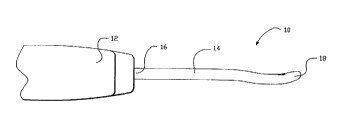
Referring now generally to Figure 1, an apparatus for control contraction
of tissue that includes collagen fibers is generally denoted as 10. Apparatus 10includes a handpiece 12 that is preferably made of an insulating material. Typesof such inculating materials are well known in those skilled in the art. An
electrode 14 is associated with handle 12 at a proximal end 16 of electrode 14,
and may even be attached thereto. A distal end 18 of electrode 14 has a
geometry that delivers a controlled amount of energy to the tissue in order to
achieve a desired level of contraction of the collagen fibers. Contraction is
achieved while ~iiee~ otion and breakdown ofthe collagen fibers is minimiæd.
Electrode 14 can have be a flat elongated structure that is easily painted
across a tissue without "hanging up" on any section of the tissue. In one
geometry of electrode 14, all edges 20 of distal end 18 are radiused, as
illustrated in Figures 2 and 3. Distal end 18 can have a variety of geometric
... ,,,1;~ ,,.,1;.. ,~ One such geometry is a disc shaped geometry without square
edges. Electrode 14 cam be made of a number of different materials includimg
but not limited to stainless steel, platinum, other noble metals and the like.
Electrode 14 can be made of a memory metal, such as nickel titanium,
commercially available from Raychem Corporation, Menlo Park, California. In
Figure 4, a resistive heating element 22 can be positioned in an interior lumen of
electrode 14. Resistive heating element can be made of a suitable metal that
transfers heat to electrode 14, causing electrode distal end 18 to become
deflected when the ~ UICi of electrode 14 reaches a level that the memory
metal is caused to deflect, as is well known in the art. Not all of electrode 14need be made of the memory metal. It is possible that only electrode distal end
18 be made of the memory metal in order to effect the desired deflection. There
are other methods of deflectmg electrode 18, as will be more fully discussed anddescribed in a later section of this gr~ifil~otinn
Apparatus 10, comprising handpiece 12 and electrode 14, is adapted to
be introduced through an operating cannula for.~ v~ ~ It
- -
W0 95/30373 . ~
~ 2~88668
will be appreciated that apparatus 10 may be used in non~
I.l.li,_l,....~ and that an operating cannula is not necessary in the broad
application of the invention.
- As illustrated in Figures 5 and 6, apparatus 10 can also include, as an
integral member, an operating cannula 24 which can be in the form of a
,ld~ , trocar with ~im~on~ione of about 3 to 6 mm outside diameter, with
tubular geometries such as those of standard ~- " . ~ y available operating
cannulas. Operating cannula 24 can be made of a variety of 1.;,,~.. ~, ~ ;1,
rnaterials including but not limited to stainless steel, and the like.
Operating caDnula 24 has a proximal end that attaches to handpiece 1 2
and it can have a sharp or piercing distal end 26 that pierces a body structure in
order to introduce electrode 14 to a desired site. Electrode 14 is positioned
within an interior lumen of operating carmula 24 and is extendable beyond distalend 26 in order to reach the desired tissue site. ~lectrode 14 cam be advanced
and retracted in and out of operating cannula 24 by activating a ~ul~luy~
button 28 which is located on the exterior of handle 12. Deployment button 28
is preferably activated by the operator merely by sliding it, which causes
electrode 14 to advance in a direction away from distal end 26 of operating
cannula 24. Deployment button 28 can be pulled back, causing a retraction of
electrode 14 towards distal end 26. In many instances, electrode 14 will be
retracted to be positioned entirely within operating cannula 14. Electrode 14
cam also deployed with fluid hydraulics, rnf l nn~ti.~S, servo motors, linear
actuators, amd the like.
An electrical amd/or fluid flow cable 28 attaches to handle 12 and
provides the necessary connection of apparatus 10 to a suitable energy source
andlor a source of fluid, which may be an electrolytic solution or an electrolytic
gel. An electrolytic solution, for purposes of this invention, is one that increases
the traDsfer of thermal energy from electrode 14 to a tissue. Suitable electrolytic
solutions include but are not limited to saline solution and the like.
Il
woss/30373 r~ .,....o~32
21~8~i68
A variety of energy sources can be used with the present invention to
transfer thermal energy to the tissue that includes collagen fibers. Such energysources include but are not limited to RF, microwave, ultrasonic, coherent lightand thermal transfer.
When an RF energy source is used, the physician can activate the energy
source by the use of a foot switch 30 that is associated with handle 12 and
electrode 14. ~;. ";~ y,acontrolledamountofRFenergyisdeliveredso
that there is an effective transfer of thermal energy to the tissue site so that the
thermal energy spreads widely through the tissue but does not cause a
~liccori,qtil-n or breakdown of the collagen fibers.
For many ~l,l ,l i. q:;l .l l~, it is necessary to have electrode distal end 18 to
become deflected (Figure 6). This can be achieved with the use of memory
metals, or it can be ~ . A mqrhqnir,qlly. A steering wire, or other
mr~h^ qirql structure, is attached to either the exterior or interior of electrode 14.
A deflection button 32, located on handle 12, is activated by the physician,
causing steering wire 34 (Figure 7) to tighten, and impart an retraction of
electrode 14, resulting in a deflection of electrode distal end 18. It will be
that other mechanical ' can be used in place of steering
wire 34. The deflection may be desirable for tissue sites that have difficult
access, and it is necessary to move about a non-lmear tissue. By deflecting
electrode distal end 18, the u,u~ullllll;ly to provide more even themmal energy to
a tissue site is achieved, and the possibility of ablating or .1; ~. ,. l ;.... of
collagen material is greatly reduced.
As shown in Figure 7, steering wire 34 attaches to a flat formed on the
2~ exterior of electrode 14. Wire EDM technology can be used to form the flat on
electrode 14. A "T" bar .. I~yl.. ,.l ;r ~ is illustrated in Figure 7. Chemical
etching may be used to create the "T" bar. Steering wire 34 need not be an
actual wire. It can also be a high tensile strength cord such as Kevlar. Steering
wire 34 can be made of stainless steel flat wire, sheet material, and the like.
12
WO 95/30373 . ~
~ 2188668
Electrode 14 can be tubular in nature with a central lumen. Electrode
distal end 18 can include a conductive plug that is sealed to electrode distal end
18 by welding, e-beam, laser, and the like.
In Figure 9, Electrode 14 can include an electrical insulation layer 38
formed on a back side of electrode 14 which is intended to minimize darnage to
tissue areas that are not treated. For example, when electrode 14 is introduced
irlto a tight area, and only one surface of the tight area is to be treated, then it
desirable to avoid delivering thermal energy to other tissue site areas. The
inclusion of insulation layer 38 ~ this result. Suitable insulation
materials include but are not limited to polyimide, epoxy varnish, PVC and the
like. Electrode 14 includes a conductive surface 40 which does not include
insulation layer 38.
A plurality of apertures 42 are formed in electrode 14 to introduce a
flowing fluid 44 through an interior lumen of electrode 14 and to the tissue site.
The flowing fluid can be an electrolytic solution or gel, including but not
limited to saline. The electrolyte furnishes an efficient electrical path and
contact between electrode 14 and the tissue to be heated.
Referring now to Figure 10, electrode 14 includes a central lumen for
receiving an electrolytic solution 44 from an electrolytic source. Electrolytic
solution 44 flows from electrode 14 through a plurality of apertures 42 formed
in conductive surface 40. An insulating housing 46 surrounds electrode 14,
leaving only conductive surface 40 exposed. Insulating housmg 46 can be
formed of a variety of Cl~,~,Ll;l,ally conducting materials includmg but not
limited to Li~ lw~ ~Li~ p plastic resins, ceramics, and the like~
2~ Insulating housing 46 rides along the surface of the tissue to be treated and
positions conductive surface 40 in an adjacent but spaced .~ ,, with the
tissue. In this manner, there isn't direct contact of conductive surface 40 withthe tissue, and the chance of 1 ~ ;- " . or break down of the collagen fibers isreduced. Insulating housing 46 creates a partial dam 48 of electrolytic solutionadjacent to the tissue. Electrical energy 15 transferred from electrode 14 to
.
wo95130373 2 1 8 8668 ~ 43z
electrolytic solution 44, and from electrolytic solution 44 in dam 48 to the
tissue. A cuff 50 surrounds insulating housing 46. Cuff 50 may be made of a
varietyofmaterialsincludingbutnotlimitedtoll.. ~l-~l;.,ll.. ,~ll;.,~
plastic resins, ceramics amd the like. The respective dimensions of insulating
housing 46 and cuffcan vary according to the specific :Irrli~s-til-n For
example, in l~.,lCUt~ , the dimensions will be smaller than for
those used in topical r, F' ~' such as ~' r.~"
Cuff50 and insulating housing 46 are closely positioned to each other,
but they are spaced in a manner to create a return electrolytic solution chalmel52. The used electrolyte solution may either be released within a conflned body
area, such as the joint, or not be returned to the tissue, but instead is removed.
Use of a cooled solution to deliver the thermal energy to the tissue,
instead of direct contact with conductive surface 40, provides a more even
thermal gradient in the tissue. Avoidance of surface ~ g can be
;" '~ d There is a more uniform level of thermal energy applied to the
tissue. Electrolytic solution 44 may be cooled in the range of about 30 to 55
degrees C.
Referring now to Figure 11, electrolytic solution 44 is in a holding
container 54 and transferred through a fluid conduit 56 to a t~ L..C
controller 58 which can cool and heat electrolytic solution 44 to a desired
t~ c. A pump 60 is associated with fluid conduit 56 to transfer fluid
throughout the system and delivers electrolytic solution 44 through handpiece
12 to electrode 14. Returning electrolytic fluid 44 passes through return
electrolytic solution chalmel 52, and is delivered to a waste container 62. The
flow rate of electrolytic solution can be in the range of less than about Icc/min.
to greater than 5cc/second.
The area of electrode 14 that serves as conductive surface 44 can be
adjusted by the inclusion of an insulating sleeve 64 (Figure 12) that is
positioned aroumd electrode 14. Sleeve 64 is advanced and retracted along the
surface of electrode 14 in order to provide increase or decrease the surface area
14
WO 95/30373 r~ ?
21 88668
of conductive surface 44 that is directed to the tissue. Sleeve 64 can be made of
a variety of materials including but not limited to nylon, polyimides, other
Il ,. . " " ,~ and the like. The amourlt of available conductive surfaee 44
available to deliver thermal energy can be achieved with devices otber tbAn
. 5 sleeve 64, includirlg but not limited to printed circuitry with multiple cireuits
that can be i~ldividu~lly activated, and the like.
Electrode 14 ean have a variety of different geometrie cr~fi~Ptir~nc In
one Glllbvduu~,.lL, electrode 14 has an oval cross section (Figure 13). The ovaleross section provides a greater eonduetive surfaee 44 area that is in eontaet
with the tissue. A larger zone of heating to the tissue is provided. The thermalgradient within the tissue is more even and the possible .l; .~v ~ , or
breakdown of the eollagen fibers is redueed.
As illustrated in Figure 14, operating cannula 24 includes a viewing
scope 66 which may be positioned above electrode 14 (Figure 15). Vievring
scope 66 provides a field of view 68, permitting the surgeon to view while
deliverying energy to the tissue site and contraeting the tissue. Viewing seope
66 ean inelude a bundle light l~ ;"g fibers and optieal viewing elements.
Alternatively, the surgeon ean view the procedure under 01 Llrlu~,u~
vi~l-Ali7Ptinn
Referring now to Figure 16, one or more i , G serlsors 70 ean be
positioned in electrode 14, ~OI i ' ly at electrode distal end 18. Temperature
sensor 70 can be a ~hr ~mr~rollrlr a thermistor or phosphor coated optical fibers.
Temperature sensor 70 can be utilized to determine the ~ l'G of electrode
14, p~Li~,uLuly at conductive surface 40, or t~ LulG sensor 70 may be
employed to determine the L~ u~ of the tissue site.
Additionally, the apparatus of the present invention ean be an RF energy
delivery deviee to effect contraction of collagen soft tissue while " ., "; ",;,; "~
..A111~ or breakdown of the collagen fibers. As sho~vn in Figure 17 the
apparatus for control contraetion of collagen soft tissue can include handpiece
30 12, electrode 14, operating cannula 24, able 28 and an RF power source 72.
WO 95/30373 r~ 7
2 1 88668 ~ ~
Suitable RF powe} sources are cul~ c;dlly available and well known to those
skilled in the art. In one .,l..L ' of the invention RF power source 72 has a
single channel, deliverying ~ ly 30 watts of RF energy and possess
continued flow capability. A closed loop feedback system, coupling
t~ ,la~UI~ sensor 70 to RF energy source 72 can be included. The t~ Lulc
of the tissue, or of electrode 14 is monitored, and the power of RF generator 72adjusted ~cvl~..f51y. The physician can, if desired, over~ide the closed loop
system. A lll;.,.u~lu.,c.,av 74 can be included and illCUl,U ' ~ into the closedloop system switch power on and off, as well as modulate the power. A suitable
l~ lUI!lUc~,~avl is, ~,;olly available and well known to those skilled in the
art of closed loop feedback systems. The closed loop system utilizes
IlliclulJlv~ aul 74 to serve as a controller, watch the L~ ,U~ Ulc, adjust the RF
power, look at the result, refed the result, and then modulates the power.
Optionally positioned on electrode distal end 18 is a conductive roller
element 76 (Figure 18). Conductive roller element is rotatably mounted on
electrode distal end 18 and carl include a plurality of projections 78. Roller
element 76 is moved across the tissue site, along with projections 78, to deliver
the thermal energy.
The present invention provides a method of contracting collagen soft
tissue. The collagen soft tissue is contracted to a desired shrinkage level
without .l . ~v :A1 i.... and breakdown of the collagen structure. It cam be used in
the shoulder, spine, cosmetic ~ , and the like. It will be ~ c ' to
those skilled in the art that the present invention has a variety of different
~rrli~ ti~nc. not merely those specifically mentioned in this ~l ~ .i ri..-: ;....
Some specific ~ include joint capsules, specifically the gleno-
humoral joint capsule of the shoulder, herniated discs, the meniscus of the knee,
in the bowel, for hiatal hernias, abdominal hernias, bladder ~ , tissue
welding, DRS, and the like.
RF energy, thermal energy, is delivered to collagen soft tissue. The
thermal energy penetrates more than l mm through the collagen soft tissue. The
16
wo g~/30373 r~ 32
21 88668
penetration can be as much as about 3 mm. Electrode 14 is painted across the
collagen soft tissue sequentially until the maximum shrinkage occurs. In one
....l ,o.l; ... ~ the collagen soft tissue is contracted irt an amount of about two-
thirds of its resting weight. A ~ lUtC range of about 43 to 90 degrees C is
preferred. More preferred, the ~ "l" A' r range is about 43 to 75 degrees C.
Still more preferred is a l~ L~c range of 45 to 60 degrees C.
In one specific l . . ,l .o.l;. .l of the invention, joint capsules are treated to
eliminate capsular lcd~ld~ . More specifically, the invention is utili~ed to
contract soft collagen tissue in the gleno-humoral joint capsule of the shoulder.
The basic anatomy of the gleno-humoral joint capsule of the shoulder is
illustrated in Figure 19.
The apparatus of the present invention provides RF heating irl a fluid or
saline CllVilUIIIII~II to control thermal spread. RF heating is applied to collagen
connective tissue shrinkage in t~,lll~l~.lll.AC ranges of about 43 to 90 degrees C,
43 to 75 degrees C and 45 to 60 degrees C. The RF energy is delivered through
t ...lf.~ y guided handpiece 12 in a fluid or saline CllVilUl~ llL within the
joint. It can be under ~ULLIU ~U~ V 5~ 1 by the surgeon, or the apparatus
can include a viewing device. The invention accurately controls the application
of heat within a specific thermal range, and delivers thermal energy to collagensoft tissue of the joint, thereby contracting and restricting the soft tissue
elasticity and improving joint stability. When applied to the shoulder, there iscapsular shrinkage of the gleno-humoral joint capsule of the shoulder and a
consequent contracture of the volume, the interior ~,;I~,lllllf~.ICII~,~" of theshoulder capsule to correct for recurrent instability symptoms. The degree of
capsular shrirJkage is determined by the operating surgeon, based on severity of~JICUIJ.,I.lliVC symptoms and condition of the capsule at the time of ~u LLtu~-,ui);c
inspection. The maximum amount of collagen contraction achieved is
'y two-thirds of its original structure.
In Figure 20, a loose capsule is illustrated. The apparatus for control
contraction of tissue of the present invention is applied to a joint capsule (Figure
17
wo 95130373 1 ~ s432
21 ~8fi68
21). Electrode distal end 18 is painted across the surface of the collagen soR
tissue. Figures 23 and 24 illustrate the application of the invention to a
herrliated disc.
While ~ ~ ' and ~ ;. ., .c of this invention have been shown
S and described, it will be apparent to those skilled in the art that many more
than mentioned above are possible without departing from the
invention concepts herein. The invention, therefore, is not to be restricted
except in the spirit of the appended claims.
18