Note: Descriptions are shown in the official language in which they were submitted.
CA 02204952 1997-OS-09
ARTICULATION TRANSMISSION MECHANISM
FOR SURGICAL INSTRUMENTS
Background of the Invention
This invention relates to surgical instruments for performing various surgical
procedures, especially endoscopic surgical procedures. In particular, it
relates to the
instrument mechanism which allows the surgeon to precisely position the
instrument at
the endoscopic surgical site conveniently and with a high degree of
confidence.
During a surgical procedure, particularly an endoscopic surgical procedure,
access to the surgical site within the body cavity may be provided through
openings of
a small diameter made in the body wall. An instrument frequently used to
provide this
access is the trocar. The trocar is an assembly which includes an obturator
and a
cannula. The obturator has a sharp tip which is used to puncture the body wall
to
provide the access opening. The obturator slides within the cannula, which is
a
hollow, cylindrical sleeve. When the obturator has punctured the body wall,
the
obturator is removed from the cannula. The cannula, however, remains in place
within the opening made in the body wall by the obturator. Consequently, the
cannula
provides a cylindrical passageway to gain access to the surgical site within
the body
cavity.
Accordingly, a characteristic feature of many endoscopic surgical instruments
is a long cylindrical shaft which can slide through the trocar cannula. At the
business
end of the shaft, which is the end of the instrument coming into contact with
tissue at
the surgical site within the body cavity, an "end effector" is provided to
manipulate
the tissue in some way to carry out a desired surgical procedure. The business
end,
including the end effector, must likewise be capable of sliding through the
trocar
cannula. At the opposite end of the shaft, there is an actuator operatively
connected to
the business end to remotely control the performance of the end effector. The
actuator
is conveniently housed in a frame which may include a pistol grip handle with
one or
more pivoting triggers. Alternatively, the actuator may include a lever, or
the
END-277
CA 02204952 1997-OS-09
-2-
combination of a pivoting trigger and a lever. The actuator is activated when
the
surgeon pivots the trigger or depresses the lever. These actions in turn cause
the end
effector to perform its desired function.
Before the surgeon can actuate the end effector to manipulate tissue to
perform
a desired surgical procedure, the end effector must be carefully positioned at
the
desired location within the endoscopic surgical site. It also must be
positioned at a
proper orientation if, for example, staples must be fired in a certain
direction to
properly fasten the tissue. Therefore, endoscopic surgical instruments
typically
include mechanisms to enable the surgeon to vary the orientation and
positioning of the
end effector at the business end of the instrument. Of course, the mechanisms
must be
operable at or near the frame of the instrument so that the surgeon can easily
manipulate and control these mechanisms while gripping the instrument with his
hand.
Often, it may be desirable to rotate the end effector of an endoscopic
surgical
instrument about the long axis of the shaft of the instrument to vary the
orientation of
the end eifector. Accordingly, many endoscopic surgical instruments include a
knob
or dial on or adjacent the frame which, when actuated by the surgeon's hand,
rotates
the shaft of the instrument and correspondingly rotates the end effector.
Another critical feature of certain endoscopic instruments is the ability to
pivot
the end effecwr so that the end effector is positioned at an "articulated"
position
relative to the long axis of the shaft. Consequently, endoscopic instruments
often
include an articulation knob or dial on or near the frame for remotely
articulating the
end effector for precise positioning of the end effector within the endoscopic
surgical
site. Numerous examples of these articulation mechanisms for endoscopic
surgical
instruments abound. For example, the reader is encouraged to review U.S.
Patent
Nos. 4,728,020; 4,869,414; 5,312,023; 5,326,013; 5,330,502; 5,374,277;
5,381,943; 5,383,888; 5,403,342; 5,405,344; 5,409,498; 5,411,519, 5,417,203
and
5,456,684. Articulating mechanisms for pivoting the end effector are also
described
END-277
CA 02204952 2005-11-16
-3-
in U.S. Patent Nos. 5,601,224 and 5,626,432.
Also of interest is U.S. Patent No. 5,632,432, which describes a
mechanism for bending the end effector of an endoscopic instrument
through a flexible portion of the shaft.
Although articulating endoscopic surgical instruments are now
freely available in commerce and have been described in the literature, the
mechanisms which control articulation typically have a significant
drawback. When the end effector of the instrument is articulated to a
desired position, the end effector is often pushed against the tissue before
the end effector is manipulated to perform the desired surgical function. In
some cases, the surgeon intentionally uses the articulated end effector to
push against the tissue because the surgeon desires to retract or dissect
tissue to provide sufficient space within the site for accurately manipulating
the end effector to perform the surgical function. Unfortunately, what often
occurs when a force is applied to the end effector in an articulated position
is that the end effector is forced from its desired articulated position. In
other words, the end effector "unwinds" from its desired articulated
position, and may shift to another undesired articulated position or revert
back to its original, unarticulated position. Obviously, this is a nuisance
which would be desirable to overcome.
In addition, when resistance to movement from an articulated
position is provided in the articulation assembly to maintain proper
positioning (as described in U.S. Patent No. 5,601,224 discussed above), a
corresponding resistance must likewise be provided when the surgeon
articulates the end effector to its desired articulated position. In other
words, the surgeon must apply a greater force or torque on the articulation
knob or dial in order to provide a corresponding increase in the resistance
of the end effector to movement from the articulated position.
CA 02204952 1997-OS-09
-4-
Furthermore, if too great a force is applied to the end effector in an
articulated
position, not only may the end effector unwind, but also the components of the
articulation assembly may break, leading to a catastrophic failure.
Accordingly, a surgical instrument is needed which characteristically includes
an end effector at the business end of the shaft which is capable of being
remotely
articulated to properly position the end effector. The ability to remotely
articulate the
end effector is especially important for endoscopic surgical instruments,
which
characteristically include an elongated cylindrical shaft separating the frame
of the
instrument from the end effector. Significantly, the mechanism for
articulation would
desirably resist movement of the end effector in an articulated position when
a force is
applied to the end effector. Additionally, resistance would be provided
without
requiring excessive force to position the end effector from an unarticulated
to an
articulated position. Furthermore, it would be desirable if a fail safe
mechanism to
prevent component breakage were provided which could reset the articulation
assembly if too great a force were applied to the articulated end effector.
Summary of the Invention
In its broadest sense, the invention is an articulating surgical instrument
which
comprises an articulation transmission assembly. The articulation transmission
assembly remotely articulates an end effector of the instrument. The
articulation
transmission assembly has a detent housing, a compressible deck, an actuator
and a
drive member. Each of these components of the articulation transmission
assembly
will now be described briefly.
The detent housing is mounted on the instrument. It contains a plurality of
detent teeth in the housing.
END-277
CA 02204952 1997-OS-09
_$_
The compressible deck contains a plurality of ratchet teeth on the deck. The
deck teeth are matingly coupled with the detent teeth of the detent housing
when the
articulation transmission assembly is in a first lock position.
The actuator is fitted on the detent housing. It applies a rotational force on
the
deck. When such a rotational force is applied to the deck by the actuator, the
deck
compresses. As the deck compresses, the deck teeth decouple from the detent
teeth.
The decoupling of the teeth facilitate ratcheting rotation of the deck from
the first
locked position to a second locked position.
Finally, the drive member of the articulation transmission assembly is in
communication with the deck. It translates rotational movement of the deck
into axial
movement of an elongated transmission member which is attached to the drive
member.
1$
The articulation transmission assembly of the surgical instrument of this
invention provides the surgeon with the ability to remotely articulate the end
effector
of the instrument. Rotation of the actuator provides axial movement of the
elongated
transition member to articulate the end effector.
Significantly, rotation of the actuator of the articulation transmission
assembly
decouples the teeth of the deck from the detent housing to significantly
reduce the
resistance to rotation. Consequently, when rotational resistance is reduced,
the desired
articulation of the end effector is more readily facilitated. If a rotational
force is not
2$ applied to the actuator, the articulation transmission assembly rests in a
locked
position. When the end effector is in a locked, articulated position, a
greater force
must be applied on the end effector to decouple the teeth and consequently
change the
articulated position because the deck will not be subjected to compression
resulting
from rotation of the actuator. Therefore, when the surgeon wants to rotate the
actuator for articulation, the resistance to rotation is significantly less
than the
END-277
CA 02204952 1997-OS-09
' -6-
resistance which must be overcome when a force is applied to the articulated
end
effector.
In addition, the articulation transmission assembly of the surgical instrument
provides for ratcheting rotation of the end effector. Since force can be
applied to
decouple the teeth of the deck from the teeth in the detent housing, the
amount of total
force which the components of the articulation transmission assembly is
subjected can
be limited. Consequently, the articulation transmission assembly of this
invention
provides a fail-safe mechanism to prevent component breakage.
In a preferred embodiment of this invention, an articulating surgical
instrument
particularly adapted for endoscopic surgery is provided. The instrument
comprises a
frame which includes a hand grip for gripping and manipulating the instrument
at a
first end of the instrument. An elongated endoscopic shaft extends from the
frame.
The shaft has a longitudinal axis. The instrument has an end effector in
communication with the shaft at an opposite end of the instrument for
manipulating
tissue to carry out a desired surgical function. The end effector is movable
to provide
articulation of the end effector from a first position parallel to the shaft
longitudinal
axis to a second position angled from this axis.
The preferred instrument has an articulation transmission assembly adjacent
the
frame for remotely articulating the end effector from the first position to
the second
position. This articulation transmission assembly includes a nozzle and an
articulation
body. The nozzle is coupled to the shaft and secured to the frame. It has a
body with
a bore extending through it generally parallel to the shaft longitudinal axis.
It also has
a detent housing extending from the nozzle body. The detent housing contains a
plurality of detent teeth in the housing. The articulation body is mounted
within the
detent housing of the nozzle body for rotational movement from a plurality of
locked
positions spaced between a plurality of unlocked positions. The articulation
body
END-277
CA 02204952 1997-OS-09
_7_
includes a deck, a drive member and a lever. A brief description of these
components
will now be set forth.
The deck has a pair of spaced-apart deck halves separated by mutually-opposed
first and second detents. Each of the deck halves has a plurality of deck
teeth. The
deck teeth are positioned for interacting relationship with the detent teeth
of the detent
housing. When the articulation body is in one of the locked positions, the
deck teeth
mesh with the detent teeth. In contrast, when the articulation body is in one
of the
unlocked positions, the deck teeth do not mesh with the detent teeth.
The drive member of the articulation body is coupled to the deck. The drive
member descends into the bore of the nozzle body. It has first and second
elongated
transmission members attached to it. These transmission members extend through
the
bore into the shaft for remotely articulating the end effector in response to
actuation of
the articulation transmission assembly.
Finally, the lever of the articulation transmission assembly is secured to the
articulation body for rotating the articulation body within the detent housing
of the
nozzle. The lever includes a cap fitted on the detent housing. The cap
contains a slot
within the cap for receiving the f rst and second detents of the deck halves
so that the
deck halves of the deck are attached to the cap.
Significantly, when a rotating force is applied to the lever of the
articulation
transmission assembly, the slot in the cap urges the first and second detents
toward
each other. In so doing, the deck teeth are withdrawn from the detent teeth,
and
rotation of the articulation body within the detent housing from the locked
positions to
the unlocked positions is therefore facilitated.
The preferred embodiment of the instrument of this invention is particularly
adapted for endoscopic surgery because it facilitates the remote articulation
of the end
END-277
CA 02204952 1997-OS-09
_g_
effector adjacent the frame of the instrument. In addition, the use of the
slot in the cap
of the lever to urge together the deck halves to withdraw the teeth of the
deck from the
teeth in the detent housing is a simple and effective mechanism for reducing
the
rotational forces which the surgeon must apply to the lever when he wants to
articulate
the end effector. In effect, the spaced-apart deck halves of the articulation
body
provide a compressible deck assembly within the articulation body. When the
lever is
rotated, the walls of the slot apply a compressive force on the first and
second detents
of the deck halves to urge the deck halves together. Thus, the deck teeth are
readily
withdrawn from the detent teeth.
In the most preferred erribodiment of this invention, the end effector of the
surgical instrument of this invention is a surgical fastening assembly, and
the
instrument is an articulating surgical stapler particularly adapted for
endoscopic
surgery. The surgical fastening assembly has an elongated anvil facing an
elongated
channel for receiving a staple cartridge. The surgical fastening assembly is
capable of
clamping tissue, and then firing staples into the clamped tissue.
The instrument of this invention can be used in any surgical application where
it is desirable to remotely articulate an end effector of the instrument to
better position
the end effector at the surgical site. Remote articulation is particularly
desired for
endoscopic surgical applications, although it may also be desirable for
conventional,
open surgical procedures.
Brief Description of the Preferred Embodiment
Figure 1 is a foreshortened side elevational view of the preferred
articulating
surgical stapler of this invention. A portion of the frame of the stapler has
been
exposed to show the attachment of the articulation transmission assembly of
the stapler
to the frame.
END-277
CA 02204952 1997-OS-09
-9-
Figure 2 is a plan view of the stapler of Figure 1 illustrating the remote
articulation of the surgical fas:ening assembly of the stapler in response to
the actuation
of the articulation transmission assembly.
Figure 3 is an exploded isometric view of the articulation transmission
assembly of the stapler of Figure 1.
Figure 4 is a side elevation view of the lever cap of the articulating
transmission assembly of Figure 3.
Figure 5 is a bottom view of the lever cap of Figure 4.
Figure 6 is a plan view of the articulation body of the articulation
transmission
assembly of Figure 3.
Figure 7 is a side elevational view of the articulation body of Figure 6.
Figure 8 is a front elevational view of the articulation body of Figure 6.
Figure 9 is a plan view of the nozzle of the articulation transmission
assembly
of Figure 3.
Figure 10 is a side elevational view of the nozzle of Figure 9.
Figure 11 is a plan view of the articulation transmission assembly of the
stapler
of Figure 1 in which the articulation body of the assembly is shown in a
locked
position. The lateral sides of the lever cap have been truncated to illustrate
the internal
details of the assembly. The top of the lever cap has been further sectioned
away to
illustrate the interface between the cap and the articulation body.
END-277
CA 02204952 1997-OS-09
- 10-
Figure 12 is a transverse section of the articulation transmission assembly
generally taken along line 12-12 of Figure 11. The articulation body of the
assembly
is shown in the locked position to prevent the surgical fastening assembly of
the stapler
from changing articulation angle.
Figure 13 is a transverse section of the articulation transmission assembly of
Figure 12 in which the articulation body of the assembly has been rotated from
the
locked position to an unlocked postion for articulation of the surgical
fastening
assembly of the stapler.
Figure 14 is a plan view similar to Figure 11 except that the articulation
body
has been rotated to the unlocked position.
Detailed Description of the Preferred Embodiment
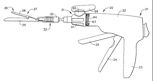
Referring initially to Figure 1, there is shown the preferred articulating
endoscopic stapler 20 of this invention. At a first proximal end 21, the
stapler has a
frame 22 adapted to enable the user to grip and manipulate the stapler. The
frame has
a stationary hand grip 23 for placement in the palm of the user's hand, and
pivotally
mounted clamping and firing triggers, 24 and 25, for remotely clamping tissue
and
firing staples into the clamped tissue, respectively.
At an opposite distal 26 end of the stapler 20 there is the end effector in
the
form of a surgical fastening assembly 27. The surgical fastening assembly has
an
elongated anvil 28 facing an elongated channel 29 adapted to receive a
surgical
cartridge containing a plurality of staples therein (surgical cartridge not
shown).
Extending from the frame 22 of the stapler and coupling the frame to the
surgical
fastening assembly 27 is an elongated endoscopic shaft 30.
END-277
CA 02204952 2005-11-16
-11-
The preferred actuation assembly within the frame of the
stapler for remotely clamping tissue and firing staples into the
clamped tissue in response to pivotal counterclockwise rotation
of the clamping and firing triggers is described in U.S. Patent
Nos. 5,465,895 and 5,553,765. The preferred clamping
mechanism within the surgical fastening assembly to urge the
anvil from a first position spaced from the elongated channel to
a second position adjacent the channel is described in U.S.
Patent No. 5,662,667.
Referring to Figures 1 and 2, the preferred articulating
stapler 20 has an articulation transmission assembly 31 coupling
the frame 22 to the elongated endoscopic shaft 30 of the stapler.
When the articulation transmission assembly is rotated, it causes
the remote articulation of the surgical fastening assembly 27 of
the stapler. The elongated endoscopic shaft contains a flexible
neck 32 enabling the articulation of the surgical fastening
assembly 27 of the stapler. The flexible neck has first and
second flexible neck portions, 33 and 34, which receive first and
second elongated flexible transmission bands, 35 and 36. Upon
rotation of the articulation transmission assembly, one of the
first and second flexible transmission bands is moved forwardly
and the other band is moved rearwardly. In response to the
reciprocating movement of the bands within the first and second
flexible neck portions of the flexible neck, the flexible neck
bends to provide articulation. A further description of the
flexible neck in an articulating endoscopic stapler is described
in U.S. Patent No. 5,632,453.
The component parts of the articulation transmission
assembly 31 are illustrated in Figure 3. The major components
of the assembly are an actuator 37, an articulation body 38 and a
nozzle 39. Rotational movement of the actuator 37 causes
CA 02204952 1997-OS-09
-12-
corresponding rotation of the articulation body 38 within the nozzle 39. The
first and
second elongated transmission bands, 35 and 36, consequently reciprocate
axially in
opposite directions parallel to the longitudinal axis of the endoscopic shaft
30 of the
stapler to cause the remote articulation of the surgical fastening assembly
through the
flexible neck of the endoscopic shaft.
Referring specifically to Figure 3 in combination with Figures 6-8, a detailed
illustration of the articulation body 38 is provided. The articulation body
has a deck
40 consisting of first and second spaced-apart, semicircular deck halves, 41
and 42.
The deck halves are mutually opposed to each other and essentially represent
mirror
images of each other. The first and second deck halves have protruding from
their
surfaces mutually opposed first and second detents, 43 and 44. Each deck half
has a
set of deck teeth 45 spaced about 180° from the set of deck teeth on
the other deck
half.
The articulation body also has a generally circular base 46. The base has a
pair of rotation stops 47 descending from its surface as well as a pair of
finger recesses
48. The base 46 flexibly supports the deck 40 on two sets of beams. First
inner and
outer flexible beams, 49 and S0, extend upwardly from the base and are
integrally
attached to the first deck half 41. Likewise, second inner and outer flexible.
beams, S1
and 52, extend upwardly from the base and are integrally attached to the
second deck
half 42. The first and second outer flexible beams, and the first and second
inner
flexible beams, are displayed in mutually opposed relationship.
Again focusing on Figure 3 and Figures 6-8, the articulation body 38 further
includes a drive gear 53 descending from the base 46. The drive gear has a
flared
opening 54 through it, and a lower pivot 55. Within the flared opening of the
drive
gear, there is a firing rod orifice 56 for receiving the firing rod 57
enabling the firing
of staples into the clamped tissue in response to pivotal rotation of the
firing trigger
(see Figure 12). Coring cavities 58 are embedded in the base for manufacturing
END-277
CA 02204952 1997-OS-09
-13-
optimization. The drive gear is coupled to a pair of drive racks, 59 and 60,
on the
flexible elongated transmission bands, 35 and 36, to effect the desired
reciprocating
movement of the bands.
The nozzle 39 of the articulation transmission assembly is specifically
illustrated in Figure 3 in combination with Figures 9 and 10. The nozzle has a
nozzle
body 61. The nozzle body has an axial bore 62 extending through it for
receiving the
drive gear 53 of the articulation body 38. The bore provides a continuous
opening
axially from the frame into the elongated endoscopic shaft, and therefore the
firing rod
57 and other operative components of the stapler can communicate with the
surgical
fastening assembly 27 from the frame 22. The nozzle body also has a frame
groove
63 and flange 64 to fasten the body of the articulation transmission assembly
to the
frame (see Figure 1).
Extending from the nozzle body 61 of the nozzle 39 is a detent housing 65.
Within the housing, there is an annular array of detent teeth 66. Spaced from
the
detent teeth is a detent housing floor 67. The floor 67 is displayed adjacent
to the
nozzle body 61. It has a pair of ledges 78 which interact within the rotation
stops 47
of the articulation body to limit the degree of rotation. When the
articulation body is
inserted into the detent housing, the base of the articulation body sits on
the floor
within the detent housing, and the deck teeth 45 of the first and second deck
halves, 41
and 42, of the deck 40 are aligned with the detent teeth 66 of the detent
housing to
provide an essentially continuous surface. Additionally, when the articulation
body is
inserted, the lower pivot 55 of the drive gear 53 is received in a pivot hole
68 located
interiorly within the nozzle body adjacent to the axial bore 62 (see Figure
12).
Figure 3 in combination with Figures 4 and 5 illustrate the actuator 37 of the
articulation transmission assembly. The actuator consists of a lever arm 69, a
circular
cap 70 and a pair of retaining fingers 71. The lever arm is mounted on the top
of the
cap. The pair of retaining fingers descend downwardly from the underside of
the cap.
END-277
CA 02204952 1997-OS-09
- 14-
Each of the retaining fingers has a retaining clip 72. The retaining fingers
are
received within the finger recesses 48 of the articulation body 38. The
underside of
the cap (Figure 5) has a slot depression 73 embedded within the cap. The slot
depression is bounded by a pair of parallel slot walls 74 and diagonal flats
75.
Pressure points 76 are consequently provided at the junction between the
parallel walls
and the diagonal flats.
The first and second detents, 43 and 44, of the deck halves of the
articulation
body are inserted into the slot depression 73 within the underside of the
circular cap
70. Accordingly, the parallel slot walls 74 frictionally contact the first and
second
detents of the deck, thus securing the actuator 37 to the articulation body
38. Further,
when the articulation body is inserted into the detent housing 65 of the
nozzle body 61
so that the articulation body is retained when the firing rod 57 is received
through the
firing rod orifice 56 of the drive gear 53, the cap 70 is secured onto the
detent housing
when the cap rests on an actuator cap lid 77 of the detent housing.
Advantageously, each of the three significant components of the articulation
transmission assembly, namely the actuator, articulation body and nozzle, are
injection
molded components. The preferred material of construction for each of the
components is a glass fiber-reinforced amorphous polyamide, sold commercially
under
the trade name Grivory GV-4H by EMS - American Grilon as of the date upon
which
the application which matured into this patent was filed.
Referring now to Figures 11 and 12, there is shown the articulation
transmission assembly 31 of the stapler 20 when the assembly is in a locked
position.
In this locked position, the deck teeth 45 of the articulation body 38 are
matingly
coupled to, and mesh with, the detent teeth 66 of the detent housing 65. This
engagement of the deck and detent teeth fixes the articulation position of the
surgical
fastening assembly 27 of the stapler. The slot depression 73 within the
underside of
END-277
CA 02204952 1997-OS-09
-15-
the cap 70 of the actuator 37 frictionally receives the first and second
detents, 43 and
44, of the deck 40.
Referring now to Figures 13 and 14, there is shown the articulation
transmission assembly in an unlocked position. In the unlocked position, the
deck
teeth are decoupled and disengaged from the detent teeth. The unlocked
positions of
the articulation transmission assembly are spaced between the locked positions
of the
assembly. When a rotational force is applied to the lever arm 69 of the cap
70, the
pressure points 76 at the junction between the diagonal flats 75 and the
parallel slot
walls 74 urge the first and second detents, 43 and 44, of the deck toward each
other.
As the detents are urged toward each other, the first and second deck halves,
41 and
42, of the deck are effectively compressed toward each other to enable the
withdrawal
of the deck teeth from engagement with the detent teeth within the detent
housing of
the nozzle. When the deck and detent teeth are withdrawn and decoupled from
each
other, each tooth on the sets of deck teeth will snap into engagement with a
respective
tooth on the array of detent teeth unless additional rotational force is
applied to the
lever arm of the actuator. If additional force is applied, the pressure points
within the
slot depression of the cap will continue to urge the deck halves toward each
other, and
ratcheting rotation will occur and continue until the rotational force is
released.
Accordingly, ratcheting rotation of the articulation transmission assembly is
provided, correspondingly causing articulation of the surgical fastening
assembly in a
plurality of discrete positions angled from the longitudinal axis of the
endoscopic shaft
of the stapler. The compression of the deck in response to rotational movement
of the
lever reduces the force the user must apply to articulate the surgical
fastening assembly
relative to the force which must be overcome to cause an articulation of the
surgical
fastening assembly when pressure is applied directly to the surgical fastening
assembly.
END-277
CA 02204952 1997-OS-09
- 16-
Furthermore, when the articulation body 38 is rotated in a first direction in
response to rotational movement of the actuator 37 to cause articulation of
the surgical
fastening assembly in that first direction, a rotational position will be
reached where
the rotational stops 47 of the base 46 of the articulation body abut the pair
of ledges 78
protruding from the floor 67 of the detent housing 65. Consequently, further
rotational movement of the articulation body in the first direction, and
further
articulation of the surgical fastening assembly in that first direction, is
prevented.
Consequently, the interaction of the rotation stops with the pair of ledges on
the floor
of the detent housing acts to limit the degree of rotational movement of the
articulation
body, and thus the degree of articulation of the surgical fastening assembly
of the
stapler.
Although this invention has been described in connection with its most
preferred embodiment, numerous additional embodiments will become readily
apparent to those skilled in the art. For example, although the invention has
been
described in connection with an articulating endoscopic stapler, the invention
is equally
applicable to conventional open surgical instruments. Additionally, although
the
invention has been described in connection with an articulation transmission
assembly
which provides for remote articulation of a surgical fastening assembly, it is
equally
applicable to an instrument which provides remote articulation of a different
kind of
end effector. Accordingly, the preferred embodiment described in connection
with
this detailed description is intended to illustrate the invention only, and is
not in any
way intended to limit the scope or spirit of the claimed invention.
END-277