Note: Descriptions are shown in the official language in which they were submitted.
CA 02207400 2000-11-17
r
1
SYSTEM FOR CATHETER FIXATION
Background of the Invention
Body cavities are drained or fed with different types of tubes.
Examples of such cavities include the urinary bladder cavity, the gastric
or intestinal cavity and the post-operative cavity. Also, cystic ducts and
gall bladder spaces and other such cavities are drained or fed with rigid
or flexible tubes. The flexible tubes are made of biocompatible polymer
materials such as silicone, polyethylene, etc. These tubes have an
external part (out of the body or the organ) and an internal part. The
external part of these tubes are exposed to accidental pulling forces
which may cause the tube to dislodge out of the body.
Different methods of tube fixation to the body exist. External
fixation (skin contact fixation) of the tube includes: fastening the tube to
the skin with adhesive tapes and/or suturing the tube to the skin with
surgical threads.
Internal fixation methods include:
- balloon inflation of the tube tip to enlarge its diameter and
increase its pull-out force resistance;
use of a catheter tip which flares outward to a large
diameter by flexing of the catheter wall. Examples of such devices are
known as Malleot or Petzer catheters. In those systems, fins which are
normally flared open form the enlarged tip of the catheter. A constant
CA 02207400 1997-06-10
WO 96/18431 ' . PGT/US95I16102
2
force is required to press the flares concentrically to insert or remove the
catheter.
The main advantage of the present balloon fixation system over
the Malleot and Petzer catheters is the fact that the balloon catheter is
inserted and removed in substantially the same low profile diameter
whereas with the Malleot and Petzer catheters a substantial pull-out force
is required to close the flare and enable catheter removal. During pull-
out of the prior art catheters, the flares apply a radial and shearing force
on the body tissue surrounding the tube which may cause unnecessary
pain and trauma.
Another disadvantage of the Malleot and Petzer flared catheter
fixation systems is the low fixation force of the tube within the body. This
fixation force is limited because of the resulting desirably small pull-out
force to remove the tube. This pull-out force, as mentioned, may cause
trauma to the tissue.
The main disadvantage of the balloon fixation method is its
relatively complicated insertion procedure requiring the need for a syringe
to inflate the balloon. Also, the balloon's large area of contact with the
body tissue can cause substantial tissue irritability.
A means for remotely opening and closing flares in the body will
allow for easy insertion and removal of a catheter with a flare-type
fixation system. Also, remotely closing the flares, before removing the
catheter, allow flares with high fixation forces to be used without causing
any trauma to the tissue during removal.
CA 02207400 2000-11-17
3
Summary of the Invention
The invention relates to a system for catheter fixation to a body by
enlarging or reducing a catheter tip diameter during insertion to or removal
from
the body. More particularly, the invention also relates to a medical grade
flexible polymer tube which is used mainly as a drainage tube but is not
limited
to drainage systems. It may also be used for urological intra-urethral
sphincters,
plugs or devices or may be used as urethral, ureteral, bronchial or esophageal
catheters.
More specifically, the present invention provides a catheter device for
fixation to the human body, comprising: a catheter having a distal end and a
proximal end; the distal end comprising at least one fin, each of the fins
having
a base and a distal tip. The distal tips of the fins form a catheter tip. A
tubular
passageway between the distal end and the proximal end, defines an axis
extending along the line between the proximal end and the distal end. The fins
have a closed position and an open position, such that the distal tips pivot
about
the base and move away from the axis when the fins move from the closed
position into the open position.
The present invention also provides a catheter device for fixation to the
human body, which comprises: a catheter having a distal end and a proximal
end. The distal end includes fins, each of them having a distal tip; the fins
having a closed position and an open position. A tubular passageway extends
between the distal end and the proximal end; the passageway defining an axis
extending along the line between the proximal end and the distal end. The
closed position is a position in which the fins are closed into a tube-like
configuration with the distal tips being proximate to each other, and the open
position is a position in which the fins are flared open into a fan-like
configuration such that the distal tips are separated and farther apart from
each
other than in the closed position.
CA 02207400 2000-11-17
3a
The present invention also provides a method for fixation of a catheter to
the human body, which comprises: providing a catheter having a distal end, a
proximal end, and a tubular passageway between the distal end and the
proximal end. The distal end includes at least one fin, each of the fins
having a
distal tip, the distal tips of the fins forming a catheter tip, and the fins
having an
open position and a closed position. The catheter tip is of larger diameter in
the
open position than in the closed position, and the catheter tip is of larger
diameter than the tubular passageway when the fins are in the open position.
The catheter is inserted into a portion of the human body, and the fins are
manipulated from the closed position to the open position.
In another aspect of the invention, the system is used for closing body
organ holes such as atrio-ventricular septal defects, arterial punctures,
gastric or
intestinal leakage from a fistula, or any passage or hole to be obstructed.
The invention enables the enlargement (and reduction) of the catheter tip
diameter when located in the body by an external manipulation thereby fixing
the catheter in place. Another manipulation, external to the body or organ, is
used to return the tip diameter to its original small diameter size prior to
catheter
removal.
The invention also relates to a catheter, tube or plug with a distal-end tip
that is made up of one or more fins which can flare outwardly, thereby
increasing the diameter of the catheter tip and holding the catheter in
position in
the body.
The invention also relates to a push-tube which is used to force the fins
to flare open.
CA 02207400 1997-06-10
W
'WO 96/18431 ~ PCTIUS95116102
4
The invention also relates to a system which selectively locks the
fins in the stressed or flared-open position.
.,
The invention also relates to equipment which aids in the
installation of a catheter in the human body and its removal from the
body.
All these embodiments will become clear in the detailed
description of the invention and the attached figures.
Brief Description of the Drawings
Figure 1 is a perspective view of a urethral catheter or plug in its
closed and open positions;
Figure 2 is a cross section of the uretheral catheter or plug in its
closed and open positions;
Figure 3 is a perspective view of a pusher and grabber
mechanism used to aid in the insertion of the urethral catheter;
Figures 4a and 4b are side plan views showing the pusher and
grabber in use with the urethral catheter or plug; and,
Figure 5 is a cross-sectional view of a catheter and push-tube in
the closed and open positions, adapted for use in a male urethra.
Detailed Description of the Drawings and the Preferred Embodiment
The invention is herein described by way of example with
reference to the accompanying drawings, wherein:
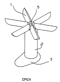
Figure 1 shows one embodiment of this invention. In this
embodiment the catheter is designed for insertion in the female urethra.
The catheter is shown with the fins in the open and closed positions.
.. ; ;v-.._,
CA 02207400 1997-06-10
' WO 96118431 . PCTIUS95/16102
The fins open within the bladder and prevent the catheter from sliding out
of the body. Element 1 designates the fins. Element 2 refers to the
catheter body. Element 3 designates the part of the catheter used to
lock the fins in an open or closed position. Element 3 has an enlarged
cross section which remains external to the urethra and prevents the
catheter from sliding into the bladder. Element 4 designates a push-tube
used to remotely open and close the fins. Element 5 designates a lumen
extending through the catheter. Figure 2 shows a cross-section of this
catheter in its open and closed positions.
As shown in Figure 2, at one end, the push-tube has an angled tip
designated 4a. The catheter body also has an angled portion
(designated 2a) which opposes element 4a. In the closed position,
elements 4a and 2a do not have the same angle. If the push tube is
pushed into the catheter body then element 4a begins to push against
element 2a. The fin material and shape are designed so that the base of
the fin is flexible enough to allow rotation of the fin around the horizontal
pivot lines. The force from the push-tube against the surface 2a forces
the fins to begin rotating outward about pivot lines 2b. When surface 2a
rotates until it fully contacts surface 4a, then the fins are in the fully
open
position. This is shown in the left side of Figure 2. These fins hold a
catheter in position in the human body.
One part of the push-tube, designated 4b, has a different diameter
than the rest of the tube. The catheter body also has a section with a
different diameter (designated 3a) which mates with 4b. The push-tube
can slide freely in and out of the catheter body until element 4b mates
with element 3a. In order for element 4b to mate with element 3a, one
or both of these must first be deformed. After surface 4b mates with 3a,
CA 02207400 1997-06-10
i , _-_11
° ~ WO 96/18431 ' ' PC'T/US95/16102
i
1
the push-tube no longer can slide relative to the catheter body and is
locked in position. As shown in the open embodiment in Figure 2,
locking the push-tube in position in the catheter body locks the fins in the
open position.
If element 3 is deformed so that 4b can slide out of 3a, then the
push-tube can slide out of the catheter body. Furthermore, the elastic
properties of the catheter tend to pull the fins back to their normally
closed position. This elastic force also helps to push the tube out of the
catheter body. Consequently, once 4b is released from 3a, the catheter
returns automatically to its normally closed arrangement, illustrated in the
right side of Figure 2.
To implant the catheter into the urethra, the catheter is first
inserted in the urethra with the fins closed. Then the push-tube is
pushed into the catheter until it mates with the catheter body (i.e.,
element 3a mates with element 4b) and locks into position. Applying a
force which deforms the catheter body enough so that elements 3a and
4b separate and the push-tube is no longer locked in position, allows the
fins to close and consequently allows for removal of the catheter from the
body.
Figure 3 shows two elements which can be used in aid in the
insertion of the catheter in the body. Element 7, the injector, is used to
help push the push-tube into the catheter for opening the fins. Element
8, the grabber, is used to hold the catheter body while the push-tube is
pushed. Figure 4 shows the injector and grabber in use. The grabber
has outwardly angled tips (8a) which can fit into the slot 3a of the
catheter. After the grabber and catheter are assembled in this manner,
':_~ CA 02207400 1997-06-10 --,
WO 96/18431 ~ PCTlUS95/16102
7
the push-tube is partially inserted into the catheter body as shown in
figure 4a. The pusher-tip (7a) of the injector 7 is then aligned with the
end of the push-tube (4c). After positioning the catheter within the body,
the user would grab the injector 7 and grabber 8 as he would a syringe;
thumb on the pusher and two fingers on the grabber. Pulling the grabber
8 towards the pusher of the injector 7 spreads the tips 8a and deforms
the slot 3a in the catheter so that it can mate with surface 4b on the
push-tube. After the push-tube is fully inserted and mated with the
catheter, continued pulling of the grabber frees its tips 8a from the
catheter (see open configuration in Figure 4b). At this point the catheter
is fully inserted in the body, the fins are open, and the grabber and the
pusher can be removed. To remove the catheter from the body, the user
must only deform the external tabs (element 3 on the catheter) by
bending or stretching so that the push-tube pops out. Once this
happens, the catheter can be freely removed since the fins return to the
closed position by their inherent elasticity and resiliency.
The basis of this invention is that the fins flare open because a
force is applied to the center of the fin base by a push-tube while the
outer edge of the fin base is held by the catheter body. In another
embodiment of this invention, the outer edge of the flare base is held by
a string or wire. In this embodiment, a grabber would not be necessary
to hold the catheter body. Instead, the string would be pulled while the
push-tube is pushed. The string would then be tied in place to lock the
fins in the flared open position. Releasing the' string would allow the
flares to close and allow for the removal of the catheter.
The specific shape of the tube and/or the fin can take many forms.
Likewise, the mating portions between the tube and the catheter can take
CA 02207400 1997-06-10
V
WO 96118431 PCTIUS95/I6102
8
many forms which will all likewise hold the push-tube in place, as
desired. .
Figure 5 shows another embodiment of the mating between the
push-tube and catheter. This embodiment is appropriate for use on a
catheter to be used in the male urethra. The outer diameter of the
mating section is the same as the catheter body diameter.
Consequently, the mating area can be located within the urethra. The
insertion of this catheter within the male urethra would be accomplished
using a pusher and grabber with distal portions that fit within the urethra.
The proximal portion of the pusher and grabber would remain external to
the body for remote opening of the fins within the bladder. After
deforming so that the push-tube and the catheter body are mated and
locked in position, the pusher and grabber can be removed.
In another embodiment of this invention the mated catheter and
push-tube have the same outer diameter as the catheter body. In
another embodiment, the deformation necessary to mate the catheter to
the push-tube locally enlarges the catheter diameter. If this enlarged
section is located in the prostatic urethra it can serve the purpose of
preventing the sliding of the catheter further into the bladder.
Removal of the catheter from the urethra would be accomplished
by inserting into the urethra a mechanical device which would deform the
catheter enough to release the push-tube. The mechanical device may
take the form of a balloon or any other device which can stretch the
catheter enough to release the push-tube.
. ;~ CA 02207400 1997-06-10
WO 96/18431 ~ PCT/US95/16102
9
The detailed description of the' device is not limited to use in the
urethra but is applicable to any kind of tube, catheter or plug used in the
' body with a fixation mechan ism. One example ofi such a tube is a
ureteral catheter in which the fins will hold the catheter in the kidney
pelvis (instead of a pig-tail ureteral catheter). Another embodiment is a
gastric or jejunal fieeding tube as well as peritoneal and post-operative
feeding tubes. The system may also be applied for closing holes in the
body such .as in arterial or vein post-puncture bleeding, heart atrio-
ventricular septal defects, or atrio-ventricular or intestinal fistulas and
punctures.
Having described this invention with regard to specific
embodiments, it is to be understood that the description is not meant as
a limitation since further variations or modifications may be apparent or
may suggest themselves to those skilled in the art. It is intended that the
present application cover such variations and modifications as fall within
the scope of the amended claims.