Language selection

Search

Patent 2208951 Summary

Third-party information liability

Some of the information on this Web page has been provided by external sources. The Government of Canada is not responsible for the accuracy, reliability or currency of the information supplied by external sources. Users wishing to rely upon this information should consult directly with the source of the information. Content provided by external sources is not subject to official languages, privacy and accessibility requirements.

Claims and Abstract availability

Any discrepancies in the text and image of the Claims and Abstract are due to differing posting times. Text of the Claims and Abstract are posted:

  • At the time the application is open to public inspection;
  • At the time of issue of the patent (grant).
(12) Patent: (11) CA 2208951
(54) English Title: ERGONOMIC HAND TOOL
(54) French Title: OUTIL A MAIN ERGONOMIQUE
Status: Expired
Bibliographic Data
(51) International Patent Classification (IPC):
  • B25G 1/10 (2006.01)
  • A46B 5/02 (2006.01)
  • B25D 1/04 (2006.01)
(72) Inventors :
  • SCHOOR, WOLFGANG (Canada)
(73) Owners :
  • SCHOOR, WOLFGANG (Canada)
(71) Applicants :
  • SCHOOR, WOLFGANG (Canada)
(74) Agent: ADE & COMPANY INC.
(74) Associate agent:
(45) Issued: 2003-10-07
(22) Filed Date: 1997-06-27
(41) Open to Public Inspection: 1998-12-27
Examination requested: 2002-06-25
Availability of licence: N/A
(25) Language of filing: English

Patent Cooperation Treaty (PCT): No

(30) Application Priority Data: None

Abstracts

English Abstract

The ergonomically improved hand tools include an improved handle which has a handle grip portion set at an angle to the tool head. The angle at which the handle grip is set to the remainder of the tool handle is a compound angle arranged such that the handle grip portion extends laterally of the remainder of the handle and angles downwards vertically into the hand when being gripped. This compound angle has the benefits of the Bennett handle as well as brings the tool head into alignment with the forearm of the individual using the handle which the Bennett handle fails to do. The improved hand tool handle is adaptable for use with most currently used hand tools and may be employed in any application where its use would be appropriate. The ergonomically improved hand tools provide an ergonomically redesigned hammer having the improved handle which reduces the risk of repetitive strain injuries. An extended fulcrum point is located at the top of the hammer head for improving the nail extracting characteristics of the hammer claw. The hammer claw has claw members that are angled relative to one another enabling the claw to access nails located in corners, along baseboards and at other locations where two surfaces meet at an angle. The hammer handle as well as the improvements discussed above includes the further improvement of being made from laminated materials which increases the strength of the hammer handle and helps dampen vibration. An improved paint brush and scissors are also provided. Both the paint brush and the scissors include the improved handle arrangement.


French Abstract

Les outils à main ergonomiques améliorés incluent un manche amélioré qui a une poignée fixée selon un angle par rapport à la tête de l'outil. L'angle selon lequel la poignée est fixée sur le reste du manche de l'outil est un angle composé, arrangé tel que la poignée s'étend latéralement par rapport au reste du manche et est inclinée vers le bas verticalement dans la main lorsqu'elle est tenue. Cet angle composé possède les avantages de la poignée Bennett et dispose la tête de l'outil dans l'alignement de l'avant-bras de l'individu à l'aide de la poignée, ce que la poignée Bennett ne fait pas. Le manche amélioré de l'outil à main est adaptable pour une utilisation avec la plupart des outils à main utilisés actuellement et peut être employé dans n'importe quelle application où son utilisation serait appropriée. Les outils à main ergonomiques améliorés fournissent un marteau redessiné de manière ergonomique équipé du manche amélioré qui réduit le risque de microtraumatismes répétés. Un point d'appui prolongé est situé en haut de la tête de marteau pour l'amélioration des caractéristiques d'extraction de clous de la griffe du marteau. La griffe du marteau possède des membres de griffe qui sont inclinés l'un par rapport à l'autre, permettant à la griffe d'accéder aux clous situés dans les coins, le long des plinthes et à d'autres endroits où les deux surfaces se rencontrent selon un angle. Le manche du marteau ainsi que les améliorations susmentionnées comportent l'amélioration supplémentaire d'être faite de matériaux stratifiés qui augmentent la solidité du manche du marteau et permettent d'amortir les vibrations. Un pinceau et des ciseaux améliorés sont également fournis. Le pinceau et les ciseaux incluent tous deux l'arrangement de manche amélioré.

Claims

Note: Claims are shown in the official language in which they were submitted.


-13-

CLAIMS:

1. A hand tool for gripping in a gripping hand of an arm of a
person, said arm having a forearm, said hand tool comprising:
a tool head;
and tool handle including:
a first portion having a first end, a second end, and a longitudinal
center line extending therethrough, said first portion being fixed at the
first end to the
tool head;
and a handle grip arranged at a compound angle to the first portion
of the tool handle and having a first end and a second end and being fixed at
the first
end to the second end of the first portion of the tool handle, said compound
angle
including:
a lateral angle arranged such that the handle grip extends laterally
of the longitudinal center line of the first portion and such that the
longitudinal center
line of the first portion of the handle lies substantially in a vertical plane
passing
through the forearm of the person; and
a vertical angle within said vertical plane passing through the
forearm of the person such that the longitudinal center line of the first
portion of the
handle lies substantially parallel to the forearm of the person when the
forearm is
positioned substantially parallel to a horizontal plane and when the handle
grip is
gripped in the hand.

2. A hand tool in accordance with Claim 1 wherein the lateral angle
is an angle lying in a range between 8 and 30 degrees.

3. A hand tool in accordance with Claim 1 wherein the lateral angle


-14-

is an angle lying in a range between 15 and 23 degrees.

4. A hand tool in accordance with Claim 1 wherein the vertical
angle is an angle lying in a range between 8 and 30 degrees.

5. A hand tool in accordance with Claim 1 wherein the vertical
angle is an angle lying in a range between 15 and 23 degrees.

6. A hand tool in accordance with any one of Claims 1, 2, 3, 4 or 5
wherein the tool head is a hammer head.

7. A hand tool in accordance with Claim 6 wherein the hammer
head includes:
a body having a front end, a rear end, a first side, a second side, a top,
a bottom, and attachment means arranged at the bottom for attaching the hammer
head to the first end of the tool handle;
and a striking member extending forwards from the front end of the
body of the hammer head to a striking face, said striking member extending
forwards
of the body at an angle to the body in a direction towards the handle grip of
the tool
handle, and said striking face being arranged substantially parallel to the
first portion
of the tool handle.

8. A hand tool in accordance with Claim 6 wherein the hammer
head includes:
a body having a front end, a rear end, a first side, a second side, a top,
a bottom, and attachment means arranged at the bottom for attaching the hammer
head to the first end of the tool handle;
a striking member extending forwards from the front end of the body to a
striking
face;


-15-

a fulcrum member extending upwards from the top of the body to an
apex spaced from said top;
and a hammer claw having a pair of spaced apart claw members each
having a first end, and a free second end and being fixed at the first end to
the rear
end of the body extending downwards and rearwards therefrom to the second end,
said claw members being arranged to diverge from one another in a direction
from
the first end to the second end thereby providing a slot therebetween.

9. A hand tool in accordance with Claim 8 wherein the fulcrum
member is arranged on the top of the body of the hammer head such that the
apex
lies at a location off set from the longitudinal centre line of the first
portion of the tool
handle towards the rear end of the body of the hammer head, and wherein the
fulcrum member extends downwards and rearwards in a curve from the apex of the
fulcrum to the claw members and wherein the fulcrum member extends downwards
and forwards in a curve from the apex of the fulcrum to the top of the body of
the
hammer head.

10. A hand tool in accordance with Claim 9 wherein the fulcrum
member includes removable and re-engageable connection means for connecting
the fulcrum member at the top of the body of the hammer head.

11. A hand tool in accordance with Claim 10 wherein the
attachment means arranged at the bottom of the body of hammer head comprise an
opening extending through the hammer head from the bottom to the top thereof,
said
opening being arranged to receive the first end of the first portion of the
tool handle
therein thereby frictionally securing the tool handle to the hammer head; and
wherein the removable and re-engageable connection means of the fulcrum member


-16-

comprise a fastener for engaging the first end of the first portion of the
tool handle
through the opening in the top of the body of the hammer head.

12. A hand tool in accordance with Claim 8 wherein each claw
member includes an inner side edge lying adjacent the slot and an outer side
edge
lying opposite the inner side edge, and wherein the claw members are arranged
at
an angle relative to one another such that the outer side edge of the second
end of
each respective claw member lies adjacent the tool handle and such that each
claw
member angles rearwards and inwards from its respective outer side edge to its
respective inner side edge.

13. A hand tool in accordance with any one of Claims 7, 8, 9, 10, 11
or 12 wherein the hammer head includes a striking face on each of the first
and
second sides thereof.

14. A hand tool in accordance with any one of Claims 1, 2, 3, 4 or 5
wherein the handle is of laminated material having a plurality of laminated
members
arranged such that each one of the plurality of laminated members extends
longitudinally along the handle.

15. A hand tool in accordance with any one of Claims 6, 7, 8, 9, 10,
11, 12, 13, or 14 wherein the handle grip is removably and re-engageably fixed
at
the first end to the second end of the first portion of the handle.

16. A hand tool in accordance with any one of Claims 1, 2, 3, 4 or 5
wherein the tool head is a paint brush head.

17. A hand tool in accordance with any one of Claims 1, 2, 3, 4 or 5
wherein the tool head is shears.

18. A handle for gripping in a hand of an arm of a person, said arm


-17-

having a forearm, and for use with a tool having a tool head, said handle
comprising:
a first portion having a first end, a second end, and a longitudinal
center line extending therethrough, said first portion being fixed at the
first end to the
tool head;
and a handle grip arranged at a compound angle to the first portion of
the tool handle and having a first end and a second end and being fixed at the
first
end to the second end of the first portion of the tool handle, said compound
angle
including:
a lateral angle arranged such that the handle grip extends laterally of
the longitudinal center line of the first portion and such that the
longitudinal center
line of the first portion of the handle lies substantially in a vertical plane
passing
through the forearm of the person; and
a vertical angle within said vertical plane passing through the forearm
of the person such that the longitudinal center line of the first portion of
the handle
lies substantially parallel to the forearm of the person when the forearm is
positioned
substantially parallel to a horizontal plane and when the handle grip is
gripped in the
hand.

19. A handle in accordance with Claim 18 wherein the lateral angle
is an angle lying in a range between 8 and 30 degrees.

20. A handle in accordance with Claim 18 wherein the lateral angle
is an angle lying in a range between 15 and 23 degrees.

21. A handle in accordance with Claim 18 wherein the vertical angle
is an angle lying in a range between 8 and 30 degrees.

22. A handle in accordance with Claim 18 wherein the vertical angle


-18-

is an angle lying in a range between 15 and 23 degrees.

23. A handle in accordance with any one of Claims 18, 19, 20, 21 or
22 for a tool head comprising a hammer head.

24. A handle in accordance with any one of Claims 18, 19, 20, 21 or
22 wherein the handle is of laminated material having a plurality of laminated
members arranged such that each one of the plurality of laminated members
extends longitudinally along the handle.

25. A handle in accordance with any one of Claims 18, 19, 20, 21 or
22 wherein the handle grip is removably and re-engageably fixed at the first
end to
the second end of the first portion of the handle.

26. A handle in accordance with any one of Claims 18, 19, 20, 21 or
22 for a tool head comprising a paint brush head.

27. A handle in accordance with any one of Claims 18, 19, 20, 21 or
22 for a tool head comprising shears.

Description

Note: Descriptions are shown in the official language in which they were submitted.


CA 022089~1 1997-06-27


ERGONOMIC HAND TOOLS
FIELD OF THE INVENTION
The present invention relates to ergonomic hand tools, particularly
of the type having bent handles.
5 BACKGROUND
Most hand tools are based on designs which have been around for
decades or centuries and can in most cases benefit from improvements in their
design made using modern ergonomic and biomechanical design and
measurement techniques. Ergonomic hand tools are generally designed to
10 minimize the effort and strain on the human body while maximizing their
efficiency.
Many diseases such as Carpal Tunnel Syndrome, Tendinitis,
Bursitis, and Tenosynovitis can be caused by repeated use of poorly designed
tools. It is known that hand tools should be designed to limit the motion of the15 wrist to the middle third of the range of motion to help reduce the risk of these
diseases. Ergonomic hand tools having bent handles to improve the efficiency
of the tool and limit the range of motion of the wrist have been known for
some time. One example of which is the Bennett handle which provides a
curved handle grip which angles vertically downwards into the hand and
20 follows the line between the index finger and the ball of the thumb. This
handle when employed for example on a hammer reduces the range of motion
of the wrist and improves the striking angle of the hammer. The Bennett
handle however does not bring the tool into alignment with the forearm. This
requires that the individual using the tool angle their wrist slightly to bring the

CA 022089~1 1997-06-27


tool into alignment with the forearm during use. This can result in repetitive
strain injuries if the tool is used often or for long periods of time.
Most hand tools have a handle which is substantially straight.
This tends to result in the tool head falling in the line of sight of the individual
5 using the tool and obscuring the work area.
SUMMARY
The ergonomically improved hand tools include an improved
handle which has a handle grip portion set at an angle to the tool head. The
handle grip is set at a compound angle to the remainder of the tool handle and
10 is arranged such that the handle grip portion extends laterally of the remainder
of the handle and angles downwards vertically into the hand when being
gripped. This compound angle has the benefits of the Bennett handle as well
as having the additional benefit of bringing the tool head into alignment with
the forearm of the individual using the tool which the Bennett handle fails to
15 do.
Add-on components providing the improved handle as well as
additional refinements are also provided as a means to improve the
characteristics of conventional hand tools.
According to one aspect of the present invention there is provided
20 a hand tool for gripping in a hand of an arm of a person, said arm having a
forearm, said hand tool comprising:
a tool head;
and tool handle including:

CA 022089~1 1997-06-27


a first portion having a first end, a second end, and a longitudinal
center line extending therethrough, said first portion being fixed at the first end
to the tool head;
and a handle grip arranged at an angle to the first portion of the
tool handle and having a first end and a second end and being fixed at the firstend to the second end of the first portion of the tool handle, said angle being a
lateral angle arranged such that the handle grip extends laterally of the
longitudinal center line of the first portion and such that the longitudinal center
line of the first portion lies substantially in a vertical plane passing through the
10 forearm of the person when the handle grip is gripped in the hand and when
the forearm is positioned substantially parallel to a horizontal plane.
Preferably the angle at which the handle grip lies relative to the
first portion of the tool handle is a compound angle comprising said lateral
angle and a vertical angle, said compound angle being arranged such that the
15 handle grip extends into the gripping hand of the person and the longitudinalcenter line of the first portion of the handle lies substantially parallel to the
forearm of the person and substantially in the vertical plane passing through
the forearm of the person when the forearm is positioned substantially parallel
to a horizontal plane.
The ergonomically redesigned hammer includes the improved
handle which reduces the risk of repetitive strain injuries. An extended fulcrumpoint is located at the top of the hammer head and is arranged to improve the
nail extracting characteristics of the hammer claw. The hammer claw has claw
members that are angled relative to one another enabling the claw to access
25 nails located in corners, along baseboards, and at other locations where two

CA 022089~1 1997-06-27


surfaces meet at an angle. An offset striking member is provided to improve
the ability of the individual using the hammer to see the work area and
improves the striking efficiency of the hammer. Additional striking surfaces
have been added to the sides of the hammer head to allow the hammer to be
5 used in applications where this may be advantageous. The hammer handle, as
well as the improvements discussed above, includes the further improvement of
being made from laminated materials which increases the strength of the
hammer handle and helps dampen vibration. An add-on fulcrum extension and
replacement handle are provided for upgrading existing hammers.
An improved paint brush and scissors are also provided. Both the
paint brush and the scissors include the improved handle arrangement. The
paint brush is provided with a handle extension making the paint brush usable
when painting in locations that would normally be out of reach of the
individual .
The improved handle is adaptable for use with many currently
used non-powered hand tools, powered hand tools, horticultural implements,
writing and office implements, edge tools, striking and impact tools, cutting
tools, ripping and riveting tools, fastening hand tools, and fo;ging and shearing
tools. The improved handle may also be employed for use with sports
equipment, kitchen utensils, and equipment controls as well as in any other
application where its use would be appropriate.
BRIEF DESCRIPTION OF THE DRAWINGS
In the accompanying drawings, which illustrate an exemplary
embodiment of the present invention:
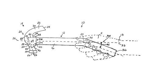
Figure 1 is a side view of the improved ergonomic hammer.

CA 022089~1 1997-06-27


Figure 2 is a top view of the improved ergonomic hammer having a
cutout showing the laminated handle.
Figure 3 is a side view of a hammer showing the add-on fulcrum
and improved handle.
Figure 4 is a view of the ergonomic hammer through line BB of
Figure 2.
Figure 5 is a side view of the ergonomically improved paint brush.
Figure 6 is a top view of the ergonomically improved paint brush.
Figure 7 is a side view of a paint brush showing a replacement
10 handle and handle extension.
Figure 8 is a top view of a paint brush showing a replacement
handle and handle extension.
Figure 9 is a top view of the ergonomically improved scissors.
Figure 10 is a side view of the ergonomically improved scissors.
15 DETAILED DESCRIPTION
The ergonomically improved hand tools include an improved
handle which has a handle grip portion set at an angle to the remainder of the
tool handle. The angle at which the handle grip is set to the remainder of the
tool handle is a compound angle which brings the tool head into alignment with
20 the forearm of the individual using the tool. The handle helps reduce many ofthe inefficiencies associated with conventional hand tool handle designs and
helps reduce the risk of repetitive strain injuries. A hammer, paint brush, and
scissors each employing the improved handle and other improvements are
provided below.

CA 022089~1 1997-06-27


Referring to Figures 1 to 4 the ergonomically improved hammer is
shown generally at 10. The hammer 10 comprises the handle 12 and a
hammer head 14. The handle 12 comprises a first portion 1Pi and a handle grip
18 fixed at an angle to the first portion 16. The hammer head 14 comprises a
5body 20, striking member 22, a fulcrum member 24, and a hammer claw 26.
The first portion 16 of the hammer handle 12 has a first end 28
and a second end 30. The first portion 16 is substantially straight extending
between the first end 28 and the second end 30 and is fixed at the first end 28
to the hammer head 14. A longitudinal center line 32 extends through the first
10portion 16.
The handle grip 18 has a first end 34 and a second end 36 and is
fixed at the first end 34 to the second end 30 of the first portion 16 of the tool
handle 12. The handle grip 18 is arranged at an angle 38 to the first portion
16. The angle 38 is a compound angle and has a lateral component 40 and a
15vertical component 42. As a result of the compound angle 38 the handle grip
18 extends laterally of the longitudinal center line 32 of the first portion 16 and
extends downwards from the first portion 16 when the first portion 16 lies in a
horizontal plane.
When the handle 12 is held in the hand 11 of an individual with
20the forearm 13 of that individual positioned substantially parallel to a horizontal
plane the lateral angle 40 brings the handle 10 and hammer head 14 into a line
with the forearm 13 such that the longitudinal center line 32 of the first portion
16 lies substantially in a vertical plane 17 passing through the forearm 13. Thevertical angle 42 brings the hammer head 14 and first portions 16 of the tool
25handle 12 down into line with the forearm 13 such that the longitudinal center

CA 022089~1 1997-06-27


line 32 of the first portion 16 of the handle 12 lies substantially parallel to the
forearm of the individual. This brings the first portion 16 of the handle 12 andthe hammer head 14 into alignment with the forearm 13 and allows the
hammer 10 to be used without bending the wrist laterally to bring the hammer
S head 14 into striking position. This also brings the hammer head 14 into a
position where it does not interfere with the line of sight between the individual
and the working area, and helps reduce the vertical range of motion through
which the wrist travels thereby keeping the wrist operating in the middle third
of its vertical range of motion thus reducing the risk of repetitive strain injuries.
10It has been found that the best arrangement of the compound
angle 38 provides a lateral angle 40 of 19~ to the longitudinal center line 32
and a vertical angle 42 also 19~ to the longitudinal center line 32. Acceptable
results can be obtained using arrangements having a lateral angle 40 Iying in
the range between 8~ and 30~ from the longitudinal center line 32 and a
15vertical angle 42 Iying in the range of between 8~ and 30~ from the longitudinal
center line 32.
The handle 12 is of laminated material comprising a plurality of
elongate laminated members 47. The elongate laminated members 47 extend
longitudinally along the handle 12 and are usually held together by an adhesive.20 The use of laminated material in the handle 12 reduces vibrations due to shock
and impact when striking with the hammer 10 and provides superior strength
when compared to similar nonlaminated materials.
The body 20 of the hammer head 14 comprises a front end 46, a
rear end 48, a first side 50, a second side 52, a top end 54, and a bottom end

CA 022089~1 1997-06-27


- 8 -
56. An attachment means 58 is arranged at the bottom 56 for attaching the
hammer head 14 to the first end 28 of the tool handle 12.
The attachment means 58 comprise an opening 60 extending
through the hammer head 14 from the bottom 56 through to the top 54 of the
S hammer head 14. The opening 60 is arranged to receive the first end 28 of thefirst portion 16 of the handle 12 and frictionally secure the handle 12 within
the opening 60 and thereby to the hammer head 14.
The striking member 22 is fixed to the front end 46 of the hammer
head 14 and extends forwards from a first end 62 fixed to the front end 46 of
10 the hammer head 14 to a second end 64. The striking member 22 extends
forwards of the body 20 at an angle angling in a direction towards the handle
grip 18 of the handle 12. A striking face 66 is fixed at the second end 64 of
the striking member 22. The striking face 66 is arranged to lie substantially
parallel to the first portion 16 of the handle 12 and to the longitudinal center15 line 32 extending therethrough. Setting the striking member 22 at an angle tothe body 20 of the hammer head 14 improves the visibility of the work area
and increases the striking efficiency of the hammer head 14.
The fulcrum member 24 is arranged at the top 54 of the body 20
of the hammer head 14 and extends upwards from the top 54 of the body 20
20 to an apex 68 spaced from the top 54. The fulcrum member 24 is arranged
such that the apex 68 lies at a location offset from the lonsitudinal center line
32 of the first portion 16 of the handle 12 towards the rear end 48 of the body
20 of the hammer head 14. The fulcrum member 24 extends downwards and
rearwards in a curve from the apex 68 to the hammer claw 26 and extends

CA 022089~1 1997-06-27


downwards and forwards in a curve from the apex 68 to the top 54 of the
body 20 of the hammer head 14.
The efficiency with which the hammer 10 can withdraw nails is
enhanced by the fulcrum member 24 which provides for greater leverage when
drawing a nail engaged within the claws 26.
The hammer claw 26 comprises a pair of spaced apart claw
members 70 each having a first end 72 and a free second end 74. Each of the
claw members 70 is fixed at the first end 72 to the rear end 48 of the body 20
of the hammer head 14 and extends downwards and rearwards therefrom to
10 the second end 74. The claw members 70 are arranged such that they diverge
from one another as they extend from the rear end 48 in a direction from the
first end 72 to the second end 74. This provides a slot 76 or engaging nails or
other fasteners when withdrawing them from a member into which they have
been introduced.
The claws 26 are arranged such that they curve steeply from the
second end 74 of each claw member 70 upwards to the apex 68 of the fulcrum
member 24. This enhances the ability of the hammer claw 26 to withdraw a
nail by drawing the nail more straightly thereby requiring less force and makingthe task easier for the individual performing it.
Each claw member 70 includes an inner side edge 78 and an outer
side edge 80 Iying opposite the inner side edge 78. The claw members 70 are
arranged at an angle relative to one another such that the outer side edge 80 atthe second end 74 of each respective claw member 70 lies adjacent the handle
12 and such that each claw member 70 angles rearwards and inwards from its
25 respective outer side edge 80 to its respective inner side edge 78. Having the

CA 022089~1 1997-06-27


- 10-
claw members arranged at an angle to one another instead of being aligned
with one another allows an individual using the hammer to withdraw nails in
corners, along baseboards, and any other location where two surfaces join at
an angle.
When performing some tasks with a hammer 10 it is sometimes
advantageous to strike a surface with a side of the hammer head 14. This is
usually not recommended when using most conventional hammers. The
ergonomic hammer 10 includes a striking face 69 on each of the first and
second sides 50 and 52 of the hammer head 14. The striking face 69 and the
stronger laminated handle 12 enables an individual to use the hammer in this
manner.
In an alternative arrangement the handle 12 and fulcrum 24 may
be provided as add-on components for use with existing hammers to convert
the hammer into a more ergonomic tool. Referring to Figure 4 the fulcrum
member 24 is shown as a separate component with a removable and
reengageable connection means 84 for connecting the fulcrum member 24 at
the top 54 of the body 20 of the hammer head 14. The removable and
reengageable connection means may be any appropriate means, one example
of which is a pair of tack members 86 fixed to a bottom 88 of the fulcrum
member 24 for engaging through the opening 60 in the top 54 of the hammer
head into the first end 28 of the first portion 16 of the tool handle 12. The
tacks 86 frictionally secure the fulcrum member 24 in place on the top of the
hammer.
The ergonomically designed handle 12 may be employed with any
tool where its application would be appropriate and may be provided with

CA 022089~1 1997-06-27


various different attachment configurations at the first end 28 for engaging thebottom 56 of the tool head.
In another alternative arrangement a paint brush 100 is provided
having a ergonomically designed handle 102 which includes the compound
angle 38 having the vertical component 42 and the lateral component 40. The
handle 102 like the handle 12 on the hammer 10 brings the working head 104
of the paint brush into correct alignment with the forearm of the individual.
The paint brush handle 102, like that of the hammer 10, has a first
portion 16 having a longitudinal center line 32 extending therethrough and a
10 handle grip 18 arranged at a compound angle 38 to the first portion 16. The
compound angle 38 is the same as that on the hammer 10. The first portion
16 of the paint brush handle 102 is fixed to the body 106 of the paint brush
head 104 which in turn is fixed to the bristles 108 of the paint brush 100.
In another alternative arrangement the paint brush handle 102 may
15 be detachable from the body 106 from the paint brush head 104 such that it
can be connected to existing paint brushes as a replacement component
thereby converting the conventional paint brush into an ergonomic paint brush.
An extension arm 110 may be provided for existing paint brushes.
The extension arm 110 would include a first portion 16, a longitudinal center
20 line 32 and a handle grip 18 fixed at the compound angle 38 to the first portion
16. This allows a regular paint brush to be used with an ergonomic handle for
reaching into locations which would otherwise be outside the reach of the
ind ivid ual .
In another alternative embodiment an ergonomic handle 120 is
shown in use with a pair of scissors 121. The ergonomic handle 120 includes

CA 022089~1 1997-06-27


the first portion 16, the longitudinal center line 32 passing through the first
portion 16, and the handle grip 18 arranged at the compound angle 38 to the
longitudinal center line 32. Like the paint brush 100 and the hammer 10 the
compound angle 38 in the handle 120 allows the working end 122, in this case
5 shears, to be correctly aligned with the forearm of the individual using the
scissors 121, allowing the scissors 121 to be used in a more comfortable
position and allowing better visibility of the area being cut.
While one embodiment of the present invention has been
described in the foregoing, it is to be understood that other embodiments are
10 possible within the scope of the invention. The invention is to be considered limited solely by the scope of the appended claims.

Representative Drawing
A single figure which represents the drawing illustrating the invention.
Administrative Status

For a clearer understanding of the status of the application/patent presented on this page, the site Disclaimer , as well as the definitions for Patent , Administrative Status , Maintenance Fee  and Payment History  should be consulted.

Administrative Status

Title Date
Forecasted Issue Date 2003-10-07
(22) Filed 1997-06-27
(41) Open to Public Inspection 1998-12-27
Examination Requested 2002-06-25
(45) Issued 2003-10-07
Expired 2017-06-27

Abandonment History

Abandonment Date Reason Reinstatement Date
1999-06-28 FAILURE TO PAY APPLICATION MAINTENANCE FEE 2000-06-27
2003-06-27 FAILURE TO PAY APPLICATION MAINTENANCE FEE 2003-07-11

Payment History

Fee Type Anniversary Year Due Date Amount Paid Paid Date
Application Fee $150.00 1997-06-27
Reinstatement: Failure to Pay Application Maintenance Fees $200.00 2000-06-27
Maintenance Fee - Application - New Act 2 1999-06-28 $50.00 2000-06-27
Maintenance Fee - Application - New Act 3 2000-06-27 $50.00 2000-06-27
Maintenance Fee - Application - New Act 4 2001-06-27 $50.00 2001-06-27
Advance an application for a patent out of its routine order $100.00 2002-06-25
Request for Examination $200.00 2002-06-25
Maintenance Fee - Application - New Act 5 2002-06-27 $75.00 2002-06-25
Final Fee $150.00 2003-07-09
Reinstatement: Failure to Pay Application Maintenance Fees $200.00 2003-07-11
Maintenance Fee - Application - New Act 6 2003-06-27 $75.00 2003-07-11
Maintenance Fee - Patent - New Act 7 2004-06-28 $100.00 2004-06-28
Maintenance Fee - Patent - New Act 8 2005-06-27 $300.00 2006-05-08
Maintenance Fee - Patent - New Act 9 2006-06-27 $300.00 2006-07-27
Maintenance Fee - Patent - New Act 10 2007-06-27 $125.00 2007-06-14
Maintenance Fee - Patent - New Act 11 2008-06-27 $125.00 2008-05-22
Maintenance Fee - Patent - New Act 12 2009-06-29 $125.00 2009-06-15
Maintenance Fee - Patent - New Act 13 2010-06-28 $125.00 2010-06-04
Maintenance Fee - Patent - New Act 14 2011-06-27 $125.00 2011-05-20
Maintenance Fee - Patent - New Act 15 2012-06-27 $225.00 2012-04-18
Maintenance Fee - Patent - New Act 16 2013-06-27 $225.00 2013-06-06
Maintenance Fee - Patent - New Act 17 2014-06-27 $225.00 2014-06-19
Maintenance Fee - Patent - New Act 18 2015-06-29 $225.00 2015-06-23
Maintenance Fee - Patent - New Act 19 2016-06-27 $225.00 2016-06-20
Owners on Record

Note: Records showing the ownership history in alphabetical order.

Current Owners on Record
SCHOOR, WOLFGANG
Past Owners on Record
None
Past Owners that do not appear in the "Owners on Record" listing will appear in other documentation within the application.
Documents

To view selected files, please enter reCAPTCHA code :


To view images, click a link in the Document Description column. To download the documents, select one or more checkboxes in the first column and then click the "Download Selected in PDF format (Zip Archive)" or the "Download Selected as Single PDF" button.

List of published and non-published patent-specific documents on the CPD .

If you have any difficulty accessing content, you can call the Client Service Centre at 1-866-997-1936 or send them an e-mail at CIPO Client Service Centre.


Document
Description 
Date
(yyyy-mm-dd) 
Number of pages   Size of Image (KB) 
Representative Drawing 1999-01-11 1 6
Drawings 1997-06-27 3 59
Abstract 2003-01-13 1 46
Claims 2003-01-13 6 236
Cover Page 2003-09-03 1 49
Cover Page 1999-01-11 2 84
Claims 1997-06-27 5 175
Description 1997-06-27 12 424
Abstract 1997-06-27 1 37
Assignment 1997-06-27 3 73
Prosecution-Amendment 2002-06-25 1 33
Prosecution-Amendment 2002-07-05 1 11
Prosecution-Amendment 2002-07-11 2 85
Prosecution-Amendment 2002-06-25 2 66
Prosecution-Amendment 2002-08-23 4 134
Correspondence 2002-09-20 1 9
Prosecution-Amendment 2002-09-24 7 234
Prosecution-Amendment 2003-01-13 11 454
Correspondence 2003-07-09 1 35
Fees 2003-07-11 1 33
Fees 2001-06-27 1 32
Fees 2000-06-27 1 36
Fees 2004-06-28 1 30
Fees 2006-05-08 2 51
Fees 2006-07-27 2 71
Correspondence 2007-09-24 2 42