Note: Descriptions are shown in the official language in which they were submitted.
CA 02217738 1997-10-08
WO 96/37255 PCT/US96/03668
MICROMINIATURE ILLUMINATOR FOR ADMINISTERING
PHOTODYNAMIC THERAPY
Field of the Invention
The present invention is generally directed to a light source for
administering
photodynamic therapy (PDT) and a method for providing such treatment, and more
specifically, pertains to an invasively disposed light source energized from a
power
supply that is electromagnetically coupled to the light source and to a method
for
using such a light source to administer PDT.
Background of the Invention
A tumor comprising abnormal cells is known to selectively absorb certain dyes
perfused into the site to a much greater extent than surrounding tissue. For
example,
compared to normal cells, intracranial gliomas absorb up to a 28 times as much
dye.
Once pre-sensitized by dye tagging in this manner, the cancerous or abnormal
cells
can be destroyed by irradiation with light of an appropriate wavelength or
waveband
corresponding to an absorbing wavelength or waveband of the dye, with minimal
damage to normal tissue. This procedure, which is known as PDT, has been
clinically
used to treat metastatic breast cancer, bladder cancer, lung carcinomas,
esophageal
cancer, basal cell carcinoma, malignant melanoma, ocular tumors, head and neck
cancers, and other types of malignant tumors, and for destroying pathogens.
Because
PDT may be selective in destroying abnormal cells that have absorbed more of
the
dye, it can successfully be used to kill malignant tissue or organisms with
less effect
on surrounding benign tissue in the brain and other critical areas.
Typically, invasive applications of PDT have been used during surgical
procedures employed to gain access to a treatment site inside the body of the
patient.
Relatively high intensity light sources have traditionally been used to reduce
the
duration of the treatment, and thus the time required for the surgery used to
expose
the treatment site, and because the majority of the prior art teaches that
very high
intensity light will more likely kill all of the malignant cells. Optical
fibers in a
CA 02217738 1997-10-08
WO 96/37255 PCT/US96/03668
- 2 -
hand-held probe are often used to deliver the intense light to the surgically
exposed
treatment site from a remote light source to reduce damage to surrounding
tissue
from the heat developed by the light source. High power lasers or solid-state
laser
diode (LD) arrays in a remote light source coupled to the optical fibers are
normally
used. A typical prior art light source for PDT would provide from about 0.10
watts
to more than I.0 watts of optical power to achieve the high intensity, short
duration
exposures that are preferred. Because of the relatively high light intensity
and power
required to achieve it, apparatus to provide PDT is often physically too large
and too
heavy to be readily moved about with the patient.
The theoretical basis behind PDT is that the light energy absorbed by dye
molecules in the malignant cells is transferred to dissolved oxygen to produce
a
reactive species called "singlet oxygen." This highly reactive form of oxygen
kills
cancer cells, damages tumor vasculature, and can destroy viruses and bacteria.
Since
the concentration of dissolved oxygen in cells is comparatively low, it is
possible that
after all available oxygen is activated and/or reacted with the cell
materials, any
additional increase in light intensity will have a negligible incremental
erect on the
tumor or in killing malignant cells. The limiting factor on the rate of
malignant cell
death in PDT may well be the rate at which additional oxygen dif~'uses into
the
treatment site from surrounding tissue and through replenishment via the
vascular
system. Contrary to the teachings of most of the prior art, the effectiveness
of each
photon of light impacting the treatment area may be highest at very low light
intensities, provided over extended treatment times, and the optical
efficiency may in
fact decrease with increasing exposure level.
Several researchers, including Haas et al., have shown that the level of
cytotoxicity in PDT appears to be proportional to the product of the
integrated light
exposure and the photoreactive agent's concentration, rather than to the
instantaneous
light intensity. In other words, the degree of PDT response is dominated by
the total
amount of light absorbed by the photoreactive agent over the treatment period.
It can
therefore be argued that if: (a) the photoreactive agent's concentration in
the target
tissue is maintained at a therapeutic level, and (b) apparatus for delivering
light of the
proper wavelength or waveband to a treatment site over an extended period is
available, then the benefits of PDT can be realized with a less aggressive and
potentially less costly treatment carried out over a period ranging from days
to weeks.
Longer treatment periods at lower dosage rates may have other benefits as
well, since
high dosage rates continued over extended periods can result in adverse normal
tissue
response.
f CA 02217738 1997-10-08
WO 96/37255 PCTIUS96/03668
-3-
Maintenance of therapeutic photoreactive agent levels at a treatment site in
the
body is not difficult. It is well known that many PDT photoreactive agents
have a
long half life in the human body. In some cases, however,
it is necessary for a patient
to avoid direct sunlight for up to 30 days to avoid sunburn
or phototoxic side effects
of the photoreactive agents that are infused into the body.
Teachings in the prior art have shown that it is possible,
in certain cases, to
obtain improved therapeutic results in PDT at a low light
level. As reported by J. A.
Parrish in "Photobiologic Consideration in Photoradiation
Therapy," pp. 91-108,
Porphyrin Photosensitization, Plenum Press, (1983), preliminary
laboratory studies
with hematoporphyrin and visible light suggest that the
reciprocity effect does not
always hold, and that low light intensity may be more effective
in PDT, in an absolute
sense. In these experiments, subcutaneous tumors in the
flanks of newborn rats were
treated with the same external dose of 620 nm radiation
at intensities of 7.5, 28, and
75 mW/cm2. At the same total light dosage, Parrish found
that greater tumor necrosis
occurred at the lowest light intensity used.
In addition, several researchers have shown that combinations
of certain
yo~oreactive--agents and -low--light levels exhibit very
potent cytotoxicity. For
example, Nitzan et al. have shown that more than 99% of
gram-positive
Staphylococcus aureus and Streptococcus faecalis bacterial
cultures can be killed with
the application of 5 mW/cmz of broad band light from a tungsten
bulb for 30 minutes,
if the cultures are initially dosed with 1-10 micrograms/ml
of deuteroporphyrin.
Continued application of light for ten to eleven hours results
in a sterile condition in
the culture, i.e., no bacteria remain alive.
Labrousse and Satre have demonstrated a similar photodynamic
extermination
of amoebae when dosed with low concentrations of 4'S'-Diiodofluorescein
isothiocyanate dextran and irradiated for about 30 minutes
with broad band light of
8-10 mW/cm2 from a tungsten lamp. Both of these experimental
results are
particularly significant because the fraction of a tungsten
lamp's output energy that
can be absorbed by either photoreactive agent is small,
since each agent has a narrow
absorbance waveband.
For all PDT light sources, the vast majority of the optical
power delivered to
tissue eventually degrades to heat. From a therapy perspective,
it is likely that this
heat load will augment the treatment due to improved chemical
reaction rates at
higher tissue temperatures. It is also true that cells kept
above approximately 43 C
are not viable. This effect is, in fact, used in the treatment
of cancer using
hyperthermia. In that situation, an attempt is made to heat
the target tumor with radio
frequency (RF) energy to a temperature on the order of 43-45
C, while maintaining
CA 02217738 2001-O1-26
75824-11
4
surrounding healthy tissue below 43°C. Combining hyperthermia
with conventional transcutaneous PDT has been shown by B.
Henderson et al. to increase the efficacy of both treatments
(see "Interaction of Photodynamic Therapy and Hyperthermia:
Tumor Response and Cell Survival after Treatment of Mice in
Vivo," Cancer Research, Vol. 45, 6071 (December 1985)).
Combining hyperthermia treatment with PDT delivered, for
example, by an implantable probe in accordance with the present
invention, will very likely augment the effects of either
treatment used alone in destroying tumors.
A wide range of therapeutic benefits may be realized
with the apparatus and methods of the present invention, beyond
destroying tumors. These benefits include, but are not limited
to, the destruction of other abnormal cell types, the
destruction of normal tissue for therapeutic ends, selective
destruction of pathogenic microorganisms, viruses, and other
self-replicating disease agents, treatment of vascular or
hematologic disorders, reducing or controlling inflammation and
the enhancement of normal cellular function, such as wound
healing or immunologic response. It is contemplated that the
PDT apparatus and method disclosed below can be applied to
providing such therapeutic benefits in both plants and animals.
A method and apparatus for delivering light with an
implantable probe, for extended periods of time, well beyond
the duration that a treatment site within a patient's body can
be exposed during surgery, is disclosed in U.S. Patent No.
5,571,152. Several embodiments of an implantable probe
suitable for this purpose are disclosed in the patent. All of
the implantable probes disclosed therein include a plurality of
light emitting diodes (LEDs) or LDs arranged in an array as the
source of light administered to an internal treatment site.
However, due to their size, a patient's body must be surgically
opened in order to implant these probes at the treatment site,
CA 02217738 2001-O1-26
75824-11
4a
and then closed as the PDT proceeds. The probe thus emplaced
provides light to the internal treatment site during the
extended PDT.
Clearly, it would be desirable to be able to insert a
light source at an internal treatment site to achieve the
benefits of extended PDT at relatively low light levels, as
taught by the above-referenced patent, without requiring that
the treatment site be fully exposed through surgery. In many
cases, surgery of this type to implant a relatively large probe
may be traumatic to a patient, particularly if already weakened
by the disease to be treated by PDT using the implantable
probe. Further, to minimize infection and the discomfort
involved with supplying electrical power to the implanted light
source probe from an external power source through conductors
that pass transcutaneously into the patient's body, it would be
desirable to supply the electrical
CA 02217738 1997-10-08
WO 96/37255 PCT/L1S96/03668
-5-
power without any such direct connection. In fact, the above-referenced patent
teaches that power can be electromagnetically coupled from an external
alternating
current (AC) power supply to an implanted probe.
Inductive coupling of electrical power to implanted pace makers and other
medical hardware from an external power supply is well known. Clearly, an
implantable probe like those disclosed in the above-referenced patent is
sufficiently
large to include an electromagnetic transformer in which electrical current
can be
induced from an external power supply. However, the prior art does not teach
or
suggest a light source for administering PDT at an internal treatment site
that is
sufficiently small to be implanted without surgically exposing the treatment
site.
Further, the prior art does not teach how an implantable probe or light source
of this
type and size might be energized remotely, without requiring a direct
connection to a
power source. Conventional electromagnetic transformers used to inductively
couple
other types of medical hardware to an external power supply are much too bulky
to
accomplish this goal. The advantages of implanting a light source to
administer PDT
without subjecting the patient to the trauma of major surgery clearly indicate
the
utility of such an invention.
Summary of the Invention
In accordance with the present invention, a microminiature light source for
providing light to an internal treatment site to effect a PDT is defined. The
light
source comprises a light emitting device that produces light of a desired
wavelength
or waveband when energized by an electrical current, and the light emitting
device
includes a supporting substrate. A plurality of electromagnetic receivers are
electrically connected to the light emitting device. Each electromagnetic
receiver
comprises a core and a plurality of turns of an electrical conductor wrapped
around
the core. The plurality of electromagnetic receivers are thus adapted to
electromagnetically couple to an external electromagnetic transmitter. An
electromagnetic field produced by the electromagnetic transmitter induces an
electrical current to flow in the electromagnetic receivers. The electrical
current
applied to the light emitting device energizes it. A biocompatible, light
transmitting
material encloses the light emitting device and the plurality of
electromagnetic
,, receivers, forming a bead. The bead is adapted for insertion into the
internal
treatment site to administer the PDT by providing light of the desired
wavelength or
waveband.
The core of each of the plurality of electromagnetic receivers comprises a
half
toroid, comprising a metallic material selected for a characteristic high
magnetic
permeability and a low magnetic hysteresis. The half toroids are oriented in a
CA 02217738 1997-10-08
WO 96/37255 PCTlUS96/03668
-6-
different direction relative to each other to improve the coupling with the
external
electromagnetic transmitter, making the coupling less dependent upon the
orientation
of the bead when inserted at the treatment site. '
The beads are generally spherical and preferably less than 5 mm in diameter.
Also, the light emitting device preferably comprises a LED. Also included is a
lens '
disposed to diffuse the light emitted by the light emitting device, thereby
increasing
the area of the treatment site that is illuminated.
Another aspect of the present invention is directed to a system for providing
light of a desired wavelength or waveband to a treatment site disposed
internally
within a patient's body, to effect a photodynamic therapy of the treatment
site. The
system includes a light source that emits light of the desired wavelength or
waveband
when energized with an electrical current, and an electromagnetic receiver
that
includes a core around which is wrapped a plurality of turns of an electrical
conductor. The electrical conductor is connected to the light source. A
biocompatible, light transmitting sheath envelopes the light source and the
electromagnetic receiver, forming a bead sized to pass through a tube. The
tube is
adapted to be inserted into a patient's body, for delivery of the bead and the
light
source contained therein to the treatment site. The system also includes a
power
supply that produces an AC voltage, and an electromagnetic transmitter that is
connected to the power supply. When energized by the power supply, the
electromagnetic transmitter is electromagnetically coupled to the
electromagnetic
receiver, thereby inducing an AC to flow in the electrical conductor wrapped
around
the core. The AC is used to energize the light source, producing light used to
administer the PDT at the treatment site. Other elements of the system are
consistent
with those of the microminiature light source discussed above.
Yet another aspect of the invention defines the steps of a method for
providing
light of a desired wavelength or waveband to an internal treatment site to
effect a
photodynamic therapy. The steps of the method include providing a
microminiature
light source that emits light of the desired wavelength or waveband. The
microminiature light source is encapsulated within a bead of a light
transmissive,
biocompatible material, and the bead encompasses an electromagnetic receiver.
The
bead is injected within the internal treatment site, and power is
electromagnetically a
coupled to the electromagnetic receiver from an external power source,
inducing an
electrical current to flow in the electromagnetic receiver. The electrical
current ,
energizes the microminiature light source.
Other steps of the method are generally consistent with the functions
performed by the elements of the system described above.
CA 02217738 1997-10-08
WO 96/37255 PCT/US96/03668
_ 7 _
Brief Description of the Drawing Fi res
The foregoing aspects and many of the attendant advantages of this invention
will become more readily appreciated as the same becomes better understood by
reference to the following detailed description, when taken in conjunction
with the
accompanying drawings, wherein:
FIGURE 1 is an isometric view of a microminiature light source that is
encapsulated to form a bead;
FIGURE 2 is a plan view of an alternative embodiment of the microminiature
light source;
FIGURE 3 is an elevational view of an electromagnetic transmitter that is used
to couple power to the microminiature light source;
FIGURE 4 is a block diagram of the components comprising a system that
includes the microminiature light source;
FIGURE S is a cross-sectional view of a portion of a patient's skull, showing
how a syringe and needle are used to inject a plurality of microminiature
light sources
into a brain tumor;
FIGURE 6 is a cross-sectional view of a portion of a patient's skull, showing
how a syringe and catheter are used to inject a plurality of microminiature
light
sources into a brain tumor; and
FIGURE 7 is side elevational view of a patient's upper torso, showing an
. array of electromagnetic transmitters used to couple power to a plurality of
microminiature light sources that have been injected into a brain tumor.
Description of the Preferred Embodiment
To minimize or eliminate the need to surgically expose an internal treatment
site in order to implant a light source suitable for administering PDT over an
extended
time, the light source must be made smaller than any previously disclosed
implantable
light source. It should be noted that the present invention is directed to an
implantable light source, i.e., to a source that is implanted within a
treatment site and
actually produces light that illuminates the treatment site. According, the
present
invention is not directed to a light source that is actually external to the
treatment site,
such as at the proximal end of an optical fiber, and does not include in the
definition
of light source as used herein, the distal end of such an optical fiber from
which light
is emitted to irradiate a treatment site in which the distal end of the
optical fiber is
disposed.
The prior art implantable light source probes for administering PDT have
included a plurality of light sources organized in an array. Such probes are
clearly too
large to be transcutaneously disposed within an internal treatment site
without first
CA 02217738 1997-10-08
WO 96/37255 PCT/US96/03668
_ g _
surgically incising and exposing the treatment site or creating a relatively
large
opening in the patient's body through which the probe can be inserted into the
treatment site. In contrast, the present invention greatly reduces the size of
the light
source used to administer the PDT so that it can be readily inserted into a
treatment
site with only a minimal incision or in many cases, with no incision (other
than a
Dul_l_ctl_Ire~ he1_i-'1_P Pf117trP(~ Ittc aarl of cincT a nlmralit . rW'
l;r.L,+
t- ~ a r--1 ~ t''~~ u~~~=ig a y mum'y vt ubm soLiri.es-dIJpSJeC~-Irl-d3I
array, as in the prior art implantable probes, the present invention
preferably employs
only a single source of light disposed in a microminiature, generally
spherical form
that is sufficiently small in diameter to be injected into the treatment site
and remotely
powered by an electromagnetic inductive coupling to an external power source.
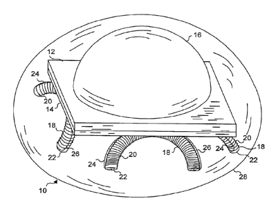
Referring to FIGURE l, a first embodiment of a microminiature light source
bead 10 in accordance with the present invention is illustrated. Light source
bead 10
includes a single LED chip 12, which is mounted back-to-back with a rectifier
chip 14
(optional). A diffusing lens 16 is disposed over the light emitting junction
(not
separately shown) of LED chip 12. Diffusing lens 16 diffuses the light
produced by
the LED junction and defocuses the light to increase the area of the treatment
site.
The light is thus emitted from light source bead 10 in approximately a
hemispherical
pattern. Preferably, the diameter of light source bead 10 is less than 5 mm. A
prototype of the light source bead has been produced having a diameter of
about
5 mm. With further care in fabrication and perhaps as the techniques for
microminiaturization improve, it is expected that the diameter of the light
source bead
can be substantially further reduced. Ideally, the beads should be as small as
possible
to permit them to be more readily injected within a treatment site.
Power must also be provided to energize the microminiature light source.
Clearly, connecting the light source to an external power supply through an
electrical
conductor would be impractical and would defeat many of the advantages of the
microminiature light source bead. Furthermore, providing an onboard battery
supply
would, with the current state of the technology, be impractical, due to the
increased
size and potentially harmful effects of any chemicals contained within the
battery that
might leak from the bead. Instead, the present invention includes means for
remotely
electromagnetically coupling power to energize the light source from an
external AC
power supply. Mounted under rectifier chip 14 are four electromagnetic
receivers 18.
Each electromagnetic receiver comprises a half toroid core 22 about which is
wrapped a plurality of turns of an electrical conductor 20. The electrical
conductor
S
used for this purpose must be very small in diameter, e.g., less than 30
gauge, in order
to enable a sufficient number of turns of the conductor to be wrapped on the
core to
provide about 4 mA of DC required to energize the LED chip. More than 10 feet
of
CA 02217738 1997-10-08
WO 96/37255 PCT/US96/03668
_g_
electrical conductor were coiled on each of the half toroid cores in the
prototype
device. Half toroid cores 22 preferably comprise a ferrite material, which is
suitable
for producing an electromagnetic coil, due to its relatively high magnetic
permeability
and low magnetic hysteresis; however, other materials known to be suitable by
those
of ordinary skill in the art of producing electromagnetic coils can instead be
used for
this purpose.
Although the preferred embodiment shown in FIGURE 1 includes only four
electromagnetic receivers 18, it is contemplated that either fewer or more
electromagnetic receivers may alternatively be included within the
microminiature
light source bead. In addition, it may be desirable to produce a
microminiature light
source bead that includes two light emitting devices mounted with the
electromagnetic receivers disposed in between and so that light is emitted
from both
hemispheres of the light source bead. In this case, there would be no need to
include
optional rectifier chip 14, since one of the LED chips could be energized
using the
positive half cycles of the induced AC current, while the other LED chip is
energized
using the negative half cycles. A second embodiment microminiature light
source
bead 1 f shown in FIGURE 2 is more suitable for this modification, due to the
flatter
configuration of the electromagnetic receivers in that embodiment. The LED
chips
could more readily be mounted on opposite sides of the electromagnetic
receivers.
For the first embodiment shown in FIGURE 1, electromagnetic receivers 18
are mounted under rectifier chip 14 so that the horns or outwardly facing ends
of
half toroid core 22 in each electromagnetic receiver are oriented in a
different
direction. As shown in this Figure, each electromagnetic receiver 18 is
generally
angled downwardly at approximately 45° relative to the under surface of
rectifier
chip 14, and is generally aligned with the four edges of the rectifier chip.
The purpose
of mounting the electromagnetic receivers so that they are oriented in
different
directions is to insure that the relatively random orientation of the light
source bead
aii.Lr it iJ i~ected lntV a treat111e11t Slte dVGJ 11V1. precilide eiectr-
oiTiagneti-caii~c~f3up~IfTg
power to one or more of the electromagnetic receivers. If only a single
electromagnetic receiver is provided on the microminiature bead, it may not be
possible to induce su~cient electrical current within the electromagnetic
receiver to
_ energize LED chip 12. By including a plurality of the electromagnetic
receivers
oriented in different directions, at least one of the electromagnetic
receivers should be
oriented so that the horns of its core 22 are generally directed toward the
nearest
adjacent outer surface of the patient's body, thereby efficiently coupling
power into
the electromagnetic receiver.
CA 02217738 1997-10-08
WO 96/37255 PCT/US96/03668
- 10 -
During fabrication of the microminiature light source, each of the
electromagnetic receivers is temporarily tacked in place on the undersurface
of
rectifier chip 14 with a suitable adhesive, and the coils of electrical
conductor 20 are '
electrically connected (bonded) to pads (not shown in FIGURE 1) disposed on
the
undersurface of the rectifier chip through leads 24 and 26. Thereafter, the
assembly is '
potted, fully sealing it within a light transmissive, biocompatible material
such as
silicone, forming a spherical bead 28 that completely encloses and
encapsulates LED
chip 12, optional rectifier chip 14, diffusing lens 16, and the plurality of
electromagnetic receivers I 8. The microminiature size of light source bead 10
enables
it to be implanted or injected at a treatment site within a patient's body
using a
minimal surgical technique, or with no surgery, as described below.
Furthermore, a
plurality of the microminiature light source beads can be implanted within the
treatment site at various spaced-apart locations, enabling different portions
of the
treatment site that will receive PDT to be simultaneously illuminated at the
spaced-apart locations with light produced by LED chip 12 in each of the
microminiature light source beads.
In the second embodiment, light source bead 10' (shown in FIGURE 2)
includes four electromagnetic receivers 18' mounted flat against the
undersurface of
rectifier chip 14. Leads 24 and 26 electrically couple opposite ends of the
electrical
conductor 20 coiled around half toroid core 22 in each electromagnetic
receiver to
pads 30, which are disposed on the undersurface of rectifier chip 14, adjacent
its
corners. Pads 30 are gold-plated, and leads 24 and 26 are bonded to the pads.
In all
other respects, microminiature light source bead 10' is identical to the first
embodiment shown in FIGURE 1.
A preferred embodiment of an electromagnetic transmitter 34 is illustrated in
FIGURE 3. Electromagnetic transmitter 34 is a much larger version of the
electromagnetic receivers used in the microminiature light source beads
described
above. The electromagnetic transmitter includes a half toroid shaped ferrite
core 38
around which is wrapped a plurality of turns of an electrical conductor 36.
Other
materials having high magnetic permeability and relatively how magnetic
hysteresis
can instead be used for the core, as will be apparent to those of ordinary
skill in the art
of building transformers and electromagnetic coils. Although not shown in -
FIGURE 3, an insulating tape may be wrapped around the turns of electrical
conductor 36, or the electromagnetic transmitter may be dipped in a resin to
form a .
coating that stabilizes and fixes the turns of the electrical conductor on the
core. A
return lead 40 from one end of the electrical conductor comprises one of two
leads 42
that are coupled to an AC power supply 48 (shown in FIGURE 4).
_ CA 02217738 1997-10-08
WO 96/37255 PCT/US96/03668
_ 11 _
Turning to FIGURE 4, a block diagram illustrates how electrical
power is
preferably electromagnetically coupled from a plurality of
electromagnetic
transmitters 34 to the electromagnetic receivers within microminiature
light source
bead 10 or 10'. Although FIGURE 4 shows only two electromagnetic
transmitters 34
in use, it is likely that more than two will be used to insure
that adequate power is
coupled to the light source bead to energize the LED chip,
since each additional
electromagnetic transmitter used increases the power induced
in the electromagnetic
receivers. In FIGURE 4, the microminiature light source bead
is implanted at a
treatment site 47, within a patient's body 44. Laboratory
tests have confirmed that
two or more electromagnetic transmitters 34 disposed adjacent
the surface of the
patient's body are able to noninvasively transtissue couple
sufficient power to a
plurality of electromagnetic receivers through from four
to six centimeters of tissue to
energize a single LED chip 12 with about 4 mA of current.
AC power supply 48 is
coupled to the electromagnetic transmitters, and in the preferred
embodiment,
provides an AC current to energize them, creating an electromagnetic
field at an RF
of about 70 KHz. The combined electromagnetic field produced
by the plurality of
electromagnetic transmitters 34 couples to one or more of
the electromagnetic
receivers 18 or 18', inducing a corresponding AC in the electromagnetic
receivers at
the same RF frequency. The plurality of electromagnetic receivers
are connected in
parallel with each other and in series with LED chip 12 and
optional rectifier chip 14.
Optional rectifier chip 14 is a full wave rectifier provided
to insure that both the
positive and negative cycles of the current wave form induced
in electromagnetic
receivers 18 or 18' are applied to energize LED chip 12.
LED chip 12 only emits light
when positive current flows through the junction of the chip
from the anode to the
cathode. Thus, unless full wave rectified DC is applied to
the input of LED chip 12, it
will only conduct during one half cycle of the induced current
in the electromagnetic
receiver(s). However, the rectifier chip is not required,
since it is possible to induce
sufficient current to operate the LED chip during only one
half of each cycle, and at
the radio frequency, the light output from LED chip 12 would
be almost continuous.
FIGURE 5 is a sectional view 50 of a patient's brain 56,
illustrating one
technique for implanting microminiature light source beads
10 (or 10') within a brain
tumor 46 using a syringe 58 and a needle 60. The microminiature
light source beads
are suspended within a suitable carrier fluid and drawn up
into the syringe. Although
the carrier fluid may be a saline solution, it can instead
comprise a suitable PDT
photoreactive agent for sensitizing tissue or organisms at
the treatment site.
Photoreactive agents that might be used for this purpose
include: Phthalocyanines,
Porphyrins, Ala, Chlorins, Purpurins, Pheophorbides, and
Cationic Dyes. This list of
CA 02217738 1997-10-08
WO 96/37255 PCTIUS96/03668
- 12 -
photoreactive agents is provided merely to illustrate that many such
substances are
known that can be used in connection with the present invention. The
photoreactive
agent used will sensitize the tissue or organisms to be affected by the PDT at
the
treatment site. The absorption wavelength or waveband of the photoreactive
agent
employed will be approximately the same as the wavelength or waveband of light
emitted by LED chip 12. For example, a photoreactive agent such as
Pheophorbide a
having a concentration of 5 micrograms/ml can be injected at the treatment
site. An
LED chip 12 should then be used that emits light having a wavelength of 660
nm,
which is approximately the absorption wavelength of tissue that has been
stained by
this particular photoreactive agent.
Needle 60 is inserted through a small incision in a scalp 52 and then through
an underlying hole drilled in skull 54. The needle passes through brain tissue
56 and
into brain tumor 46. The photoreactive agent may be applied to the treatment
site
separately or may be used as the carrier fluid to convey the microminiature
light
I S source bead through needle 60 and into the brain tumor. When the LED chip
within
the bead is energized by inductively coupled power, malignant tissue at the
treatment
site that is sensitized by the photoreactive agent will be killed, thereby
shrinking the
brain tumor.
In the example shown in FIGURE 5, brain tumor 46 is sufficiently large to
require PDT at a plurality of points distributed throughout the tumor.
Accordingly, a
number of additional microminiature light source beads 10 are illustrated
where
emplaced by needle 60 and syringe 58 through a series of punctures 62 made by
the
needle after access to the brain tissue is achieved using a small diameter
drill (not
shown) to drill through the patient's skull. Since the microminiature light
source
beads are implanted within the brain tumor without requiring extensive surgery
(only
a small incision in the scalp and the small holes drilled in the skull), the
trauma and
other undesirable effects of fully invasive surgery on the patient are
virtually
eliminated.
Because the light emitted by each LED chip 12 within one of the beads is
relatively low intensity, i.e., about 10 microwatts/cmz, the PDT must be
continued
over an extended period of time, e.g., for at least 72 hours. However, as
noted in the
prior art patent referenced in the Background of the Invention, extended PDT
at
relatively low light levels has been found to be even more effective than PDT
administered at high light levels for short periods of time. Accordingly,
brain ,
tumor 46 or other undesired tissue or pathogens at treatment sites in
different
portions of the body can readily be eliminated using the present invention.
CA 02217738 1997-10-08
WO 96/37255 PCTlUS96/03668
- 13 -
FIGURE 6 illustrates an alternative approach for implanting
microminiature
light source beads 10 within a brain tumor 46 (or within
a different treatment site). In
this alternative, a catheter 66 is introduced into the treatment
site and serves as a
passage through which the photoreactive agent and microminiature
light bead can be
injected into the site to carry out the PDT. One advantage
of using a catheter is that
the lumen within the catheter may be a larger diameter,
enabling current generation
microminiature beads that are about S mm in diameter to
more easily be injected into
a treatment site than through a smaller bore needle.
As illustrated in FIGURE 7, it is preferable to position
a plurality of
electromagnetic transmitters 34 at different spaced-apart
points around the treatment
site to insure that sufficient power is induced in one or
more of the electromagnetic
receivers to energize the LED(s) within each of the microminiature
light source beads.
In this example, only four electromagnetic transmitters
34 are shown in an array 68
around brain tumor 46. The array surrounds the skull of
a patient 70, who is shown
in a reclining position. Not shown in the Figure are clamps
or other devices used to
stabilize the electromagnetic transmitters in the desired
position. Since long-term
exposure--of --tissue - i:o--the - -electroW agnetic --held
-produced by electromagnetic
transmitters 34 may cause undesirable side effects, it is
contemplated that from time to
time, the electromagnetic transmitters will be moved to
a different position so that the
tissue between the ends of the half toroids comprising the
electromagnetic
transmitters will be positioned at different points around
the patient's skull (or around
other parts of a patient's body where the PDT is applied),
thereby insuring that the
tissue between the electromagnetic transmitter and the microminiature
light source
beads is subjected to the magnetic field for only a relatively
short period of time
compared to the duration of the PDT. Any harmful effects
of a strong
electromagnetic field on such tissue will thereby be minimized.
In addition to treating brain tumors, it is contemplated
that the present
invention can be used at almost any treatment site at which
PDT may be implemented
inside a patient's body. Using a needle or catheter to position
the microminiature
light source beads at the treatment site, it is possible
to reach virtually any portion of
the body without resorting to surgery to open up and fully
expose the treatment site,
to implant the light source required for PDT. It is also
contemplated that the
microminiature light source beads might be injected within
a patient's bloodstream
and allowed to circulate throughout the body, being energized
only at a selected part
of the circulatory system where the external electromagnetic
transmitters are disposed
adjacent the desired treatment site, or at predetermined
points where the beads lodge
due to their inability to pass through smaller capillaries.
Since these light source
CA 02217738 1997-10-08
WO 96/37255 PCT/US96/03668
- 14 -
beads are made of a biocompatible material, it is not necessary that they be
extracted
from the body once the PDT treatment is completed. Instead, they can be left
in place
without any harmful consequences to the patient.
Although the present invention has been described in connection with the
preferred form of practicing it, those of ordinary skill in the art will
understand that
many modifications can be made thereto within the scope of the claims that
follow.
Accordingly, it is not intended that the scope of the invention in any way be
limited by
the above description, but instead be determined entirely by reference to the
claims
that follow.