Note: Descriptions are shown in the official language in which they were submitted.
CA 02218814 1997-10-21
-1-
A COMPOSITE STENT
Background to the invention
This invention relates to a composite stmt, to a stmt
assembly which includes a composite stent device, and to a
method of making a stent.
Stents are used in lumens in a human or animal body. when
properly positioned in a lumen, a stent can contact the wall of
the lumen to support it or to force the wall outwardly.
Stents can be made from a material which enable the stmt to be
compressed transversely elastically so that they can then
recover outwardly when the compressing force is removed, into
contact with the wall of the lumen. The enhanced elastic
properties available from shape memory alloys as~a result of a
transformation between martensite and austenite phases of the
alloys make them particularly well suited to this application.
The nature of the superelastic transformations of shape memory
alloys is discussed in "Engineering Aspects of Shape Memory
Alloys", T W Duerig et al, on page 370, Butterworth-Heinemann
(1990). Subject matter disclosed in that document is
incorporated in this specification by this reference to the
document. A principal transformation of shape memory alloys
involves an initial increase in strain, approximately linearly
with stress. This behaviour is reversible, and corresponds to
conventional elastic deformation. Subsequent increases in
strain are accompanied by little or no increase in stress, over
a limited range of strain to the end of the "loading plateau".
The loading plateau stress is defined by the inflection point
on the stress/strain graph. Subsequent increases in strain are
accompanied by increases in stress. On unloading, there is a
decline in stress with reducing strain to the start of the
"unloading plateau" evidenced by the existence of an inflection
point along which stress changes little with reducing strain.
At the end of the unloading plateau, str-ess reduces with
CA 02218814 1997-10-21
-2-
reducing strain. The unloading plateau stress is also defined
by the inflection point on the stress/strain graph. Any
residual strain after unloading to zero stress is the permanent
set of the sample. Characteristics of this deformation, the
loading plateau, the unloading plateau, the elastic modulus,
the plateau length and the permanent set (defined with respect
to a specific total deformation) are established, and are
defined in, for example, "Engineering Aspects of Shape Memory
Alloys", on page 376.
Non-linear superelastic properties can be introduced in a shape
memory alloy by a process which involves cold working the alloy
for example by a process that involves pressing, swaging or
drawing. The cold working step is followed by an annealing
step while the component is restrained in the configuration,
resulting from the cold working step at a temperature that is
sufficiently high to cause dislocations introduced by the cold
working to combine and dislocations to align. This can ensure
that the deformation introduced by the cold work is retained.
The technique for introducing superelastic properties can be
varied from that described above. For example, instead of
subjecting the alloy to a heat treatment while restrained in
the deformed configuration, the alloy could be deformed beyond
a particular desired configuration and then heat treated such
that there is a thermally induced change in configuration of
the kind discussed below, the change taking the configuration
towards the particular desired configuration. Introduction of
the superelastic properties might also involve annealing at
high temperature (for example towards the recrystallisation
temperature of the alloy), followed by rapid cooling and then
a heat treatment at a lower temperature.
The properties of shape memory alloys can also involve
thermally induced changes in configuration in which an article
is first deformed from a heat-stable configuration to a heat-
unstable configuration while the alloy is in its martensi~te
CA 02218814 1997-10-21
-3-
phase. Subsequent exposure to increased temperature results in
a change in configuration from the heat-unstable configuration
towards the original heat-stable configuration as the alloy
reverts from its martensite phase to its austenite phase. It
is known from US-5197978 to make use of the thermally induced
change in configuration of an article made from a shape memory
alloy in a stent.
The use of a stmt which is formed from a shape memory alloy is
attractive because it can exert an outward force on the lumen
in which it is to be used continuously after it has been
deployed in the desired location. This allows the lumen to be
maintained open. It can also mean that the stmt remains in
the desired location. The enhanced elastic properties of shape
memory alloys also allow a stent to move and flex with a lumen
after installation. This can be particularly important when a
stent is positioned in an exposed lumen, such as a femoral or
carotid artery. Forces applied externally to these vessels can
cause them to flatten substantially.from their normally round
cross-section.
It~is important that the configuration of a shape memory alloy
stent towards which it attempts to recover while in the lumen
is properly selected. If that configuration is too small, the
stent will be loose in the lumen; this can result in the lumen
not being properly supported by the stmt and in the stent
becoming dislodged from the desired location. If the
configuration towards which the stmt attempts to recover is
too big, the residual force exerted by the stent on the lumen
. can be too high; it is thought that this could be undesirable
in some situations because of a risk of damage to the lumen.
Summary of the invention
The present invention provides a composite stmt device which
includes a restraint element which can be deformed plastically
~
CA 02218814 1997-10-21
-4-
and which can restrict the maximum transverse dimension to
which the shape memory stent sleeve can expand outwardly.
Accordingly, in one aspect, the invention provides a composite
stent device which comprises (a) a shape memory alloy stmt
sleeve which is treated so That it can exert an outward force
on a lumen in which the stent device is to be deployed, and
(b) a restraint element which restricts the maximum transverse
dimension to which the stmt sleeve can expand outwardly.
The stent device of the invention can be used in a lumen where
the size of the lumen is not known accurately. The transverse
dimension to which the stmt device expands in the lumen can
be adjusted by deformation of the restraint element, until the
transverse dimension is large enough_to ensure that an
appropriate force is exerted on the lumen. The deformation of
the stmt device will generally take place while it is located
in the lumen. The deformation involves deformation of the
restrained element, allowing the stent sleeve to recover
further towards its relaxed configuration in which recovery
forces are resolved. This can be achieved by means of an
expansion device which, when positioned within the stent
device, can expand the device by plastic deformation of the
restraint element. Accordingly, in another aspect, the
invention provides a stent assembly which comprises (a) a stmt
device of the type discussed above, and (b) an expansion device
which, when positioned within the stent device, can increase
the maximum transverse dimension to which the device can expand
by plastic deformation of the restraint element. An example of
a suitable expansion device is an inflatable balloon.
As well as restricting the maximum transverse dimension to
which the stmt sleeve can expand outwardly, the restraint
element should preferably be capable of being deformed trans-
versely with the stmt sleeve, for example under force applied
externally to the lumen in which the stent device is located.
It is possible for the restraint element to tolerate such
CA 02218814 1997-10-21
-5-
transverse deformation and to reform elastically under the
restoring force provided by the stent sleeve, while restricting
the maximum transverse dimension of the stmt device.
The presence of the shape memory alloy stmt sleeve in the
device of the invention has the advantage that the device
continues to exert an outward force against the lumen after
deployment, to support the lumen and to prevent the device from
becoming dislodged from the desired location. Generally, the
shape memory alloy component will exert the outward force as a
result of a treatment which relies on the enhanced elastic
properties which they can be made to exhibit, sometimes
referred to as superelastic or pseudoelastic properties. Thus,
for example, a stmt sleeve might be formed in a initial
configuration towards which it is to recover, and then deformed
inwardly to a deformed configuration in which it is constrained
by means of a restraint element, the assembly of the shape
memory and restraint elements providing the stent device of the
present invention. The diameter of the device when so
constrained should be less than the smallest lumen diameter
through which the device has to pass when being moved to the
intended location in which it is to be deployed.
A constraining component may be used to constrain the stent
device of the invention in the configuration selected for
delivery to a desired location in a lumen, in addition to the
constraining effect provided by the restraint sleeve. For
example, the device may be compressed transversely and held in
that configuration by means of a delivery catheter.
For some applications, the composite stent device will be
designed so that the shape memory alloy stmt sleeve exerts a
force against the restraint element and the lumen following a
thermally initiated change in phase from its martensite phase
to its austenite phase. This change can result from exposure
of the sleeve to the temperature of the human or animal body.
The use of a stmt sleeve that has been made to exert a force
CA 02218814 1997-10-21
-6-
in this way can have the advantage of preventing undesirable
deformation of the restraining sleeve prior to use. ,
The composite stent device of the invention can be delivered to
a desired location in a lumen in a human or animal body by
means of a delivery device such as a catheter. The restraint
element in the stent device can assist in deployment of the
stent device from the catheter (for example by means of a wire,
rod or other pushing implement) in that the transverse force
which is exerted by the device against the catheter is
controlled, restricting frictional effects between the device
and the catheter and deformation of the catheter by the device .
The catheter can also be used to deliver the inflatable balloon
or other device by which the restraint element is expanded to
set the desired configuration for the deployed device.
The stent sleeve can be located generally within the restraint
element; preferably, the restraint element is at least as long
as the stent sleeve so that the stent sleeve can be located
wholly within the restraint element.
The shape memory alloy used in the stmt sleeve can be a binary
alloy, generally based on nickel-titanium. Suitable binary
alloys include those in which the nickel content is at least
about 50 at . %, preferably at least about 50 . 5 at . % . The nickel
content will usefully be less than about 52 at. o, preferably
less than about 51 at.%. The sleeve can be formed from other
Ni-Ti based alloys, including alloys with ternary and
quaternary additions. Examples of elements that can be
incorporated in the alloy include Fe, Co, Cr, A1, Cu and V.
Added elements can be present in amounts upto about 10 at.%,
preferably upto about 5 at.%.
Preferably, the stmt sleeve has an open lattice structure,
which might comprise for example slits, or bigger openings. A
stent sleeve with a lattice structure can be formed by cutting
a tube . It might also be formed from wire using an appropriate
' CA 02218814 1997-10-21
_7_
bonding technique at points where wires cross. Preferably, the
deformation step of the method involves reducing the transverse
dimension of the stent device by changing the shape 'of the
lattice. The deformation can comprise applying a compressive
force to the device, generally transversely. This can result
in a reduction in the transverse dimension of the device as a
result of a bending deformation of the component arms which
define the apertures in the lattice structure. The width of
the arms will often be generally less than about 1.0 mm,
preferably less than about 0.8 mm, more preferably less than
about 0.5 mm, especially less than about 0.25 mm. When the
arms are not parallel to the direction along which the force is
applied, the bending can be between arms at the points at which
they meet; the arms themselves can often remain substantially
straight . In a stent sleeve in which the lattice structure
defines a plurality of diamond shape openings, the deformation
can then involve flattening the diamonds. When the arms
defining the apertures in the lattice structure are parallel or
nearly parallel to the direction along which the force is
applied, the deformation can involve bending the arms between
the points at which adjacent arms meet.
The deformation of the stent sleeve will be from a
configuration which represents the largest anticipated size of
lumen into which the stmt device is to be used, the device
then being capable of expanding outwardly to engage the walls
of the stent with outward deformation of the restraint element
as necessary.
The stent sleeve can be deformed elastically by transverse
compression. For example, it can be compressed by passing the
sleeve through a tapered aperture. Alternatively or in
addition, the sleeve can be deformed by application of an
elongating force, generally longitudinally of the sleeve. When
the sleeve has an open lattice structure with arms defining the
apertures in the lattice non-parallel to the longitudinal axis
of the sleeve, the deformation will tend to change the shape ._of
~CA 02218814 1997-10-21
_g_
the apertures by bending the arms at the points at which they
meet; the arms themselves can often remain substantially
straight. In a sleeve in which the lattice structure defines
a plurality of diamond shape openings, the deformation can then
involve flattening the diamonds.
Preferably, the stent sleeve is made by a process which
involves removing material from a sheath-like object, leaving
an open lattice structure that is capable of appropriate
deformation. The nature of the removal process will depend on
the material of the sheath-like object. For example, the
removal process may involve one or more of cutting, melting and
vaporising the material. Preferably, the removal process can
involve use of a laser cutting tool. Other techniques which
might be used for forming the pattern in the material include
electrical discharge machining, stamping, cutting, and etching
(especially photoetching).
Preferably, the sheath-like object from which the stmt sleeve
is formed is a tubular object, especially a cylindrical tube
with a circular cross-section.
While the removal process referred to above is preferred for
forming the stent sleeve, it might be formed in other ways, for
example from wire formed in a helical configuration, or by
welding pieces of wire together. The sleeve could also be made
from sheet material which can be formed into a tube, for
example by folding and welding.
Preferably, the wall thickness of the material of the stmt
sleeve less than about 1.5 mm, more preferably less than about
0.5 mm. Preferably, the wall thickness is at least about
0.05 mm, more preferably at least about 0.1 mm.
Preferably, the maximum transverse dimension of the stmt
sleeve (which will be its diameter when the stent device has a
circular cross-section) is not more than about 40 mm, more
CA 02218814 1997-10-21
-9-
preferably not more than about 20 mm, especially not more than
about 10 mm. Preferably, its minimum transverse dimension is
at least about 0.5 mm, more preferably at least about 1 mm.
The material and configuration of the restraint element will be
selected according to (a) the forces that will be exerted
against it by the stmt sleeve and (b) the .nature of the
technique used to expand it. It should be designed so that it
can be appropriately expanded (generally involving plastic
deformation) by the expansion device but should be capable of
appropriately restraining the transverse expansion of the stent
sleeve. It should also be sufficiently dimensioned so as not
to occlude the lumen undesirably, and not to prevent the lumen
from being bent . The thickness of the restraint element sh4uld
be sufficient to provide the necessary restraint against
transverse expansion of the stent sleeve, while preferably also
being able to bend elastically, for example when the stmt
device is subjected to a flattening force as might happen in an
exposed lumen such as a femoral or carotid artery. Such a
flattening deformation can be recovered relying on the enhanced
elastic properties of a shape memory alloy, as discussed above.
The restraint element can be in the form of a sleeve which the
stent sleeve can fit into. Such a restraining sleeve can have
a continuous outer surface such as might be formed by extrusion
or folding a continuous sheet. It might otherwise be
foraminous in the form of a mesh or perforated sheet. The
restraint element need not be a discrete component. For
example, it could be made from strips or wires wrapped around
the perimeter of the stmt sleeve . The restraint element might
be provided as a part of the stent sleeve. For example, a
restraint element formed from wires might be formed in the
stent sleeve, which can be deformed plastically during
expansion of the stmt device.
When the restraint sleeve is provided by woven wires or other
elements, the elements need not extend completely around the
CA 02218814 1997-10-21
-10-
stent sleeve. The deformation of such a restraint element will
then involve slipping of the elements within the ,weave,
possibly but not necessarily together with plastic deformation
of the material of the wires.
When the restraint sleeve is provided by one or more wires or
other elements that are wrapped around the stent sleeve, for
example helically, the elements should be selected with an
appropriate thickness to restrict transverse expansion of the
stent sleeve while also permitting transverse flattening of the
device. For example a stainless steel wire of about 0.02 mm
thickness can be used in a restraint for a 3 mm diameter stmt
sleeve.
The restraint element can be formed from a polymeric material.
Examples of suitable materials include polyolefins, halogenated
polyolefins (especially PTFE), polyesters, polyamides, natural
human or animal tissue, and so on. Polyethylene and PTFE can
be particularly suitable for many applications. Metallic
materials can be used for the restraint element such as stain-
less steels and titanium. The restraint element can be contin-
uous along the length of the stent sleeve with a tubular
configuration. It might have openings in it or be
discontinuous, for example in the form of bands or threads
provided sufficiently close together to provide the desired
restraint for the stmt sleeve. A restraint element formed
from a polymeric material can be formed with a tubular
configuration, for example by extrusion. A restraint element
formed from a metal might be provided as a mesh.
A restraint element formed from a polymeric material such as a
polyester, for use with a stent sleeve having an external
diameter before deformation (and which it attempts to recover
to) of greater than 3 mm and wall thickness of about 0.2 mm,
will typically have a wall thickness of about 0.01 to 0.2 mm,
depending on the mechanical properties of the material that is
used.
CA 02218814 1997-10-21
-11-
Introduction to the drawings
Figure 1 is an isometric view of a stent sleeve for use in the
stent device of the invention, which has been produced with an
appropriate configuration but before any thermal or mechanical
treatment intended to give the sleeve the desired deformation
behaviour.
Figure 2 is an isometric view of the sleeve shown in Figure 1,
after deformation from its initial configuration to the
configuration in which it can be inserted into a restraint
element for deployment.
Figure 3 is an isometric view of a stent comprising the sleeve
shown in Figures 1 and 2 and a restraining sleeve, being
delivered to a desired location in a lumen in a catheter.
Figure 3a is an expanded view, partially in section, through
the stent as shown in Figure 3.
Figure 4 is an isometric view, partially in section, of the
stent after delivery with an expansion device located within it
to expand it by plastic deformation of the restraint element.
Figure 5 is an isometric view, partially in section, of the
stent device located in the lumen after completion of the
delivery process.
Figure 6 shows a lumen with a device aecording to tl~e present
invention located within it.
CA 02218814 1997-10-21
_12r
Description of preferred embodiments
Figure 1 shows a stent sleeve which can be used in the stent
device of the invention. The sleeve has an open lattice
structure defined by arms 2. Openings 4 between the arms
extend through the thickness of the sleeve. The sleeve is
formed by cutting a tube, for example using a YAG laser cutting
tool. The sleeve is formed from a binary nickel-titanium alloy
containing about 50.8 at.% Ni. The sleeve is formed from.- a
binary nickel-titanium alloy containing about 50.8 at.% Ni.
The transverse dimension of this sleeve can be charged by
deformation of~the sleeve. The deformation results in changes
in the shape of the openings 4, as a result of bending the arms
at the point at which they meet. As formed from a tube, the
sleeve has an internal transverse dimension of about 4 mm. The
wall thickness of the tube and therefore the thickness of each
of the arms 2 is about 0.3 mm.
Figure 2 shows the sleeve shown in Figure 1 after it has been
deformed. The deformation involves reduction in the transverse
dimension of the sleeve. As a result, the openings 4 in the
sleeve as shown in Figure 1 effectively become slits 6. The
sleeve can be deformed in this way by application of a
longitudinal force at opposite ends of the sleeve. The sleeve
is deformed from the configuration shown in Figure 1 towards
that shown in Figure 2 under such conditions that the
deformation takes place elastically. The sleeve is then able
to revert towards the configuration shown in Figure 1 when
appropriately positioned in a lumen.
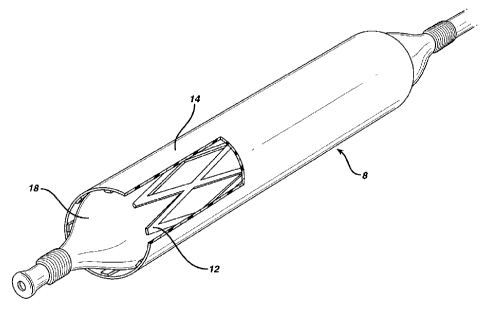
Figures 3 and 3a show the stmt device 8 of the invention being
deployed in a lumen 10 such as a blood vessel. .The stent
sleeve 12 is retained in the deformed configuration shown in
Figure 2 by means of a restraint 14, which restricts the
maximum transverse dimension to which the stent~sleeve can
expand outwardly, from the configuration shown in Figure 2
towards that shown in Figure 1. The restraint comprises a
CA 02218814 1997-10-21
-13-
sleeve formed from medical grade polyethylene, with a wall
thickness of about 0.1 mm. Use of a sleeve with this wall
thickness allows the restraint to restrict the maximum
transverse dimension of the stmt sleeve, while allowing the
stent device to be flattened at least partially. When so
restrained, the stent device including the stent sleeve can be
moved along the lumen using conventional techniques such as
involving a catheter 16.
Once located appropriately in the lumen, the stent device shown
in Figure 3 is discharged from a catheter using, known
techniques, for example by means of an inserted pusher rod.
The device of the invention can be expanded, into contact with
the internal surface of the lumen, by means of an appropriate
inflatable balloon 18, as shown in Figure 4. Inflation of the
balloon results in outward deformation of the.stent sleeve 12,
in the direction of its elastic recovery towards the
configuration shown in Figure 1. At the same time, the
restraint sleeve 14 is expanded plastically.
Figure 5 shows the device 8 installed in a lumen, after
expansion by an inserted balloon.
Figure 6 shows a lumen 20 with a device according to the
present invention located within it. The device comprises a
stent sleeve as in the device described above with reference to
Figures 1 to 5. The restraint 22 is discontinuous rather than
being formed from a sheet as shown in Figure 3. The restraint
22 comprises a plurality of substantially circumferential bands
extending around the stmt sleeve. The bands can be provided
as separate bands, or as a single band wound helically around
the stent sleeve.