Note: Descriptions are shown in the official language in which they were submitted.
CA 02225045 1997-12-18
WO 97/01094 PC IYLTS96/04584
-1-
IMPROVED RAIL INVESTIGATING ULTRASONIC TRANSDUCER
Field Of The Invention
This invention generally relates to ultrasonic transducers for the
investigation of rails and more specifically to ultrasonic transducers for
investigating the sides of webs and rail heads.
Background Of The Invention
Ultrasonic investigation of rails is well known. For example U.S.
Patent 4,165,648 describes a wheel assembly, which is adapted to ride on
top of a rail and contains a plurality of ultrasonic transducers for
investigat-
ing different parts of a rail. A pair of transducers are oriented to investi-
gate the rail along opposite longitudinal directions, another transducer is
oriented to vertically investigate the web of the rail and a fourth transducer
is intended as a side-looker with which side portions of the rail head are
to be laterally investigated.
The side-looker is mounted on a yoke assembly, near the axis and
is positioned off to one side to investigate an opposite side of the rail
head.
The transducer produces a beam intended to have a 40 degree angle
relative to the normal to the rail surface inside the rail head so that the
beam wilt intersect one of the lower corners of the head. Although this
transducer can be effective for detecting vertically split rail heads it does
not accommodate the effect of the curvature of the rail head and the head
wear that one encounters under field conditions.
CA 02225045 1997-12-18
WO 97/01094 PCT/US96/04584
-2-
The curvature of the rail head causes a variety of angles of both
compressional and shear components to be present inside the rail head
and thus creates difficulties in interpreting the resulting signals detected
at the transducer. For example, if the resultant angle is to be 40 degrees
inside the head for a compressional wave, then a 20 degree shear wave
will also be present. Since a mode conversion is relied upon to accom-
plish the resultant angle in the rail head, there is but a limited range of
incident angles available inside the wheel. This limitation arises from the
use of essentially a common exit point for all of the transducers mounted
inside the wheel and the resulting need to avoid interference with the other
transducers by internal wheel reflections from the side-looking transducer.
The '648 patent illustrates that for one particular beam direction, the
corners of one rail head and its proportionately smaller sizes are likely to
be intersected by a 40 degree beam. However, when the rail head under-
goes significant wear on its upper surface, as is often the case, the beam
will miss the lower corner. Instead the beam is likely to strike an inner sur-
face near the web, which scatters the beam inside the head, and fails to
provide the type of return needed to detect vertical flaws near the side of
the rail head.
In our patent entitled Ultrasonic Side-Looker For Rail Head Flaw
Detection, filed on March 19, 1993 bearing Serial No. 08/034,420, U.S.
Patent 5,419,196, and owned by the same Assignee as of this invention,
a side looking ultrasonic transducer is described with which a sufficiently
wide and properly angled beam within the head of a rail is achieved for the
detection of flaws such as vertical cracks extending longitudinally along
the rail.
CA 02225045 2001-06-15
-3-
Excessive wear of a rail head can occur so that the top rail
surface becomes so distorted that the detection of flaws in the side
of the rail head is obscured by reflections from other parts of the rail
such as the fillet region. The returns are then more difficult to
process with reliable detection of flaws.
SummarX of the Invention
In accordance with one aspect of the invention there is
provided an apparatus for an acoustic investigation of a rail with a
fluid filled rotating wheel inside of which is a stable yoke on which a
plurality of ultrasonic transducers are mounted for the investigation
with ultrasonic beams which exit the wheel at a generally common
area in a flexible outer membrane of the wheel as it rotates about
an axis to travel along the top running surface of the head of the rail
under inspection. The apparatus includes an ultrasonic transducer
mounted to the yoke, below the rotational axis of the wheel and
away from ultrasonic beams from other transducers, and having a
single, discrete area, focused beam emitting surface with a radius
of curvature selected so that the focal point of the ultrasonic beam,
after acoustic refraction, is located between the center of the rail and
an outer lateral surface of the rail head, said focused beam emitting
surface further being so located and sized so as to direct the
ultrasonic focused beam at the common area of the flexible outer
membrane to enter the rail head in a direction that significantly
reduces reflections from outer rail surfaces below the acoustically
refracted focal point of the ultrasonic beam inside the rail.
CA 02225045 2001-06-15
-3a-
A further aspect of the invention provides an improvement in
an apparatus for an acoustic investigation of a rail with a fluid filled
rotating wheel inside of which is a stable yoke on which a plurality of
ultrasonic transducers are mounted for the investigation of the rail
with ultrasonic beams that exit at a generally common flat area
formed in a flexible outer membrane of the wheel as it rotates about
an axis to travel along the top running surface of the rail head of the
rail under inspection and wherein the beams have different angles
relative to the normal to the top running surface to investigate
forward, backward and downward regions of the rail. The
improvement comprises an ultrasonic side-looking transducer
mounted to the yoke and located in the vicinity of the generally
common flat area below and on a side of the yoke, said side-
looking transducer being oriented so as to produce an ultrasonic
beam within the wheel fluid that is directed at the generally common
flat area with a fluid angle within a range from about 61 degrees to
about 65.5 degrees relative to a normal to the top surface of the rail,
with the normal located in a plane which is transverse to the
rotational axis of the wheel. The side-looking transducer has an
acoustic beam emitting surface with a concave curvature selected
to place the acoustically refracted focal point of the beam between
the center of the rail and a side thereof. The beam inside the rail
head has a head angle relative to the normal in the range from
about 45 degrees to about 75 degrees as measured within a plane
that is generally transverse to the top running surface of the rail,
said beam further having a width selected to produce, within the rail
head, an ultrasonic beam, at least a portion of which remains
incident on a lower corner thereof independent of the presence of
significant rail head wear and produces reflections from the lower
corner with reduced reflections from a nearby fillet region; said
reflections or an absence thereof being able to indicate the
presence of vertical rail head flaws which run generally along the
rail.
CA 02225045 2001-06-15
-3b-
With a rail investigating apparatus in accordance with the invention
a beam from an ultrasonic transducer is focused in a particular manner so
as to avoid reflections from rail side surfaces and enhance the detectability
of flaws such as vertical cracks in badly worn sides of the head of the rail.
This is achieved in accordance with one embodiment of the
invention by employing an ultrasonic transducer whose acoustic beam
emitting surface is provided with an acoustic lens that enables the
transducer to bring the acoustic beam to a focus within a rail head. The
lens focuses the beam sufficiently so as to avoid its impact on undesired
rail surfaces while having sufficient spread to investigate rail regions of
interest.
In one form of the invention a side-looking ultrasonic transducer is
provided with a concave acoustic beam emitting surface which focuses the
beam. The transducer is so located that its beam passes through an area
of a flexible membrane retaining fluid in a wheel rotating over the running
surface of a rail and is refracted towards a side of the rail head. The focal
point of the beam is located between the center of the rail and a side
surface of the head so as to avoid impacting of the beam on a fillet region
CA 02225045 1997-12-18
WO 97/01094 PCT/US96/04584
-4-
of the rail while illuminating the side of the rail head so as to produce
reflections from flaws such as vertical cracks extending along the rail.
In another form of the invention an ultrasonic transducer having a
an acoustic focusing lens is placed so as to direct a focused acoustic
beam into the web of a rail and avoid reflections from the side surfaces of
the web. This enables a faster investigation of the rail while reducing false
flaw detections.
It is, therefore, an object of the invention to provide an improved
ultrasonic apparatus for detecting flaws in a rail even in the presence of
severe rail head wear and distortions. It is a further object of the invention
to provide an apparatus for ultrasonically investigating the side of a rail
head with reduced interference from reflections by nearby surtaces such
as the fillet region of the rail.
These and other objects and advantages of the invention will be
understood from the following detailed description of several embodiments
as shown in the drawings.
Brief Description Of The Drawings
Figure 1 is a front sectional view of an ultrasonic apparatus for
investigating a rail in accordance with the invention;
Figure 2 is an enlarged perspective sectional view of an ultrasonic
transducer used in the apparatus of the invention;
Figure 3 is a partial front section view as in Figure 1 but with a
different focal length ultrasonic transducer;
CA 02225045 2001-06-15
-5-
Figure 4 is a front section view of a rail web investigating apparatus
in accordance with the invention.
Detailed Descrption Of The Drawings
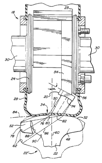
With reference to Figures 1 and 2 a wheel-type ultra-sonic
investigation apparatus 18 for ultrasonic inspection of a rail 22 is shown.
The apparatus 18 is part of a flaw detection system (not shown) that is
mounted on a carriage and includes suitable electronic signal processing
equipment to analyze the return signals detected by ultrasonic transducers
such as 20 that is mounted to a yoke 23 inside a rotating fluid-filled wheel
24. The yoke 23 and wheel 24 can be made in the manner as shown and
described in our above mentioned copending patent application, now U.S.
Patent 5,419,196
The wheel 24 is rotationally mounted to a support of the carriage
which is not shown. Typically, four wheels 24 are used, two for each rail
22. Each wheel 24 is filled with a fluid mixture of glycol and water to
improve the ultrasonic coupling through the flexible outer membrane 28.
The yoke 23 is affixed to twin axially-aligned but spaced-apart shafts, not
shown, in alignment with wheel flanges 30. The yoke 23 is held in a fixed
stable position as illustrated while the wheel 24 rotates as it travels along
the top surface 32 of rail 22. Suitable downward pressure is applied to the
wheel 24 to produce an area 34 in membrane 28 for appropriate ultra-son-
is transmission into and out of the rail 22.
Transducer 20 is a side-looking transducer and is mounted well
below the apex of yoke 23 and to its side. Transducer 20 produces an
CA 02225045 1997-12-18 pC~~S 9 6 j 04 5
1
IPEAIUS 11 JUN'
-6-
ultrasonic beam 50 that is also incident on area 34, but in a lateral
direction to investigate the side 52 of rail head 48. The transducer 20
operates in both a transmit and receive mode.
The side-looking transducer 20 is mounted to yoke 23 by way of a
removable extension bracket 54. Alternately, yoke 23 can be formed so
as to have an extension 54 become an integral part. As illustrated in the
view of Figure 1 the side-looker 20 is suspended to just below an adjacent
side flange 56, to a region that is near the flat portion 34 of the flexible
outer wheel membrane 28, but not so close as to be interfered with from
wheel vibration or bouncing effects attributable to irregularities encoun-
tered along the running top surface 32 of rail 22. If the side-looking trans-
ducer 20 is mounted on a yoke in a separate wheel, which may be wider
and/or larger, the side-looker can be located anywhere along beam 50.
The side-looker 20 further is inclined relative to the central vertical
60 to rail 22 to form an angle, alpha. The angle alpha is selected so as to
provide an optimum beam inside rail 22 for inspection of side 52 and
preferably assure that at least a portion of the beam 50 will intersect the
lower corner 62 of rail head 48. The side-looker 20 further is so sized as
to produce a sufficient beam width within the rail head 48 preferably to
assure intersection of lower side corner 62 even when a substantial
amount of the upper part of the rail head 48 has been worn away as
illustrated in Figure 1.
As illustrated in Figures 1 and 2 the side-looker transducer 20
produces a focused acoustic beam 50 by employing a lens 64 in front of
the acoustic beam generating element 66. Alternatively the lens can be
made by shaping the emitting surface of a piezoelectric element into a
AMENDED St~~
CA 02225045 1997-12-18
WO 97/OI094 PCT/US96/04584
-7-
similarly curved surface. The term lens as employed herein, therefore
encompasses both either a shaped material as illustrated in the drawings
at 64 or a similar shaping of the emitting surface of the element 66. An
acoustic absorber material 68 is used behind the element 66. The
element 66, and the absorber 68 are mounted within a cavity 70 formed
inside a housing 72 made of an appropriate material such as epoxy, which
is cast around the element 66 and the absorber 68.
The lens 64 is formed by casting or grinding away the portion of the
housing 72 that is located in front of the element 66. Either process
leaves a concave emitting surface 74. The emitting surface 74 has a
concavity that is shaped to conform along a cylinder having a radius R of
predetermined size and an axis located parallel to the longitudinal
dimension of the rail 22. The radius R is selected so that the refracted
acoustic focus 76 is located inside the rail head 48 and between the center
line 60 and a side surface 78. The acoustic focus 76 is a line of a length
commensurate with the length of the lens 64 and is located within the rail
head 48 parallel to the longitudinal dimension of the rail 22.
Alternatively the emitting surface 74 can be spherically or paraboli-
cally shaped to form a correspondingly focused conically shaped beam
inside the rail head 48.
The preferred location of the focal point is just after the entry of the
' beam 50 into the steel of the rail 22. This provides, within the steel rail
head 48, an acoustic beam whose energy is primarily contained within the
solid lines 80, 82 representing the approximate 3db points for the beam.
The dashed lines 84, 86 represent lower, 1 Odb down, energy levels of the
ultrasonic beam emitted by the transducer 20. The overall effect of the
CA 02225045 1997-12-18
WO 97/01094 PCT/US96/04584
_$_
focused beam inside rail head 48 is a substantially cleaner return
reflection from a vertical flaw such as 88 with little energy being returned
from the fillet region 90 in rail 22.
The radius of curvature of the beam emitting surface 74 and the
acoustic focal length of the beam 50 are not the same. Typically the focal
length is somewhat longer due to the acoustic travel time through the
various materials. In one embodiment of the invention the radius of
curvature for transducer 20, sized and mounted in the manner as
described herein and the aforementioned patent, was 3.125 inches and
the fluid focal length was 3.85 inches. This configuration yielded
satisfactory acoustic returns from a flaw in a rail head 48 that was as badly
worn and distorted as shown in Figure 1.
When the radius of curvature of the lens 64 is lengthened, say to
3.75 inches and maintaining other transducer configurations the same,
then the acoustic focal point 76.1 is moved, as shown in Figure 3, away
from the center line 60 towards the side surface 78. At the same time
more energy is returned from the fillet region 90 so as to reduce the clarity
of the acoustic return signals.
Hence, the radius of curvature for the (ens 64 and its associated
acoustic focal length and the location and size of the transducer are all
selected to provide a focused beam of limited width within the rail head 48.
The focal point is located so as to enable the detection of vertical flaws in
the side of the rail head with reduced reflections from the adjoining fillet
region.
CA 02225045 2001-06-15
WO 97/01094 PCT/US96/04584
_g_
Figure 4 illustrates use of a focused ultrasonic transducer 100 on
yoke in an ultrasonic rail investigating wheel 18. Transducer 100 is
used as the "0°" transducer for investigating the web 106 of rail 22'.
Since
only the low energy portions of the beam, as suggested by the 1 Odb down
' beam lines 112, 114, are likely to be incident upon the fillet regions
spurious echoes from fillet regions 108, 110 and the bottom of the rail
head 48 are substantially reduced.
In order to attain a focus beam as shown in Figure 4 a substantially
larger than usual transducer is required, of the order of about 1.5 inches
diameter. Use of such transducer would require adapting yoke to
accommodate the larger transducer 100.
Having thus described several embodiments of the invention its
advantages can be appreciated. Variations from the drawings and
description can be made by one skilled in the art without departing from
the scope of the invention as determined by the following claims.
What is claimed is: