Language selection

Search

Patent 2228911 Summary

Third-party information liability

Some of the information on this Web page has been provided by external sources. The Government of Canada is not responsible for the accuracy, reliability or currency of the information supplied by external sources. Users wishing to rely upon this information should consult directly with the source of the information. Content provided by external sources is not subject to official languages, privacy and accessibility requirements.

Claims and Abstract availability

Any discrepancies in the text and image of the Claims and Abstract are due to differing posting times. Text of the Claims and Abstract are posted:

  • At the time the application is open to public inspection;
  • At the time of issue of the patent (grant).
(12) Patent Application: (11) CA 2228911
(54) English Title: PROCESS FOR SPLITTING RESIDUES TO RECOVER SECONDARY RAW MATERIALS
(54) French Title: PROCEDE DE SEPARATION DE RESIDUS POUR OBTENIR DES MATIERES PREMIERES DE RECUPERATION
Status: Dead
Bibliographic Data
(51) International Patent Classification (IPC):
  • B03B 9/06 (2006.01)
  • B09B 3/00 (2022.01)
  • C05F 9/00 (2006.01)
  • C05F 17/00 (2020.01)
(72) Inventors :
  • FELBER, WALTER (Austria)
(73) Owners :
  • FELBER, WALTER (Austria)
(71) Applicants :
  • FELBER, WALTER (Austria)
(74) Agent: SMART & BIGGAR LP
(74) Associate agent:
(45) Issued:
(86) PCT Filing Date: 1996-06-07
(87) Open to Public Inspection: 1996-12-27
Examination requested: 2003-06-04
Availability of licence: N/A
(25) Language of filing: English

Patent Cooperation Treaty (PCT): Yes
(86) PCT Filing Number: PCT/AT1996/000103
(87) International Publication Number: WO1996/041681
(85) National Entry: 1998-02-06

(30) Application Priority Data:
Application No. Country/Territory Date
GM 310/95 Austria 1995-06-09

Abstracts

English Abstract


In this process for reducing so far unused residues from tailings, soiled
plastics from "yellow waste", strainings from sewage plants, rubbish from
dumps and sand residues to obtain and recycle secondary raw materials, said
wastes are subjected to a repeated cycle of wet and dry sieving, separation,
sorting and classification. The clean secondary raw materials obtained are
preferably conditioned in stages in an aerobic environment and, except for
difficult materials, taken directly to biological, material or raw material
processing plants. Conditioning the secondary raw materials also permits long
intermediate storage owing to the slight degree of rotting and stink. The low
investment costs make it possible to set up small plants for regional waste
economies while still offering economic advantages over competing
technologies. The system can be operated without subsequent deposition or mass
incineration for the residue processing involving about a sixth of the partial
mass flow rate of mixed plastics, composites and other materials. Residues can
be made into building materials. Fine strainings are not given any prior dry
mechanical treatment.


French Abstract

Dans ce procédé de réduction des résidus, jusque là non récupérables, issus de déchets résiduels, de matières plastiques polluantes classées jaunes, de produits piégés dans les grilles fines dans les stations d'épuration, de déchets toxiques et de résidus des bassins de dessablage, destiné à l'obtention et au recyclage de matières premières de récupération, on renouvelle plusieurs fois le cycle des techniques de classement, de tri, de séparation et de tamisage par voie sèche et par voie humide. Les matières premières de récupération propres ainsi obtenues sont, de préférence, conditionnées par étapes dans un milieu aérobie et, à l'exception des matières problématiques, sont directement soumises à des retraitements biologiques des matières premières et matières brutes. De ce fait, le conditionnement des matières premières de récupération autorise également un entreposage longue durée étant donné leur faible pouvoir odorant et de fermentation. Les faibles coûts d'investissement permettent la création de petites installations pour une gestion régionale des déchets tout en répondant à des soucis d'économies par rapport aux technologiques concurrentes. Le système peut être utilisé sans dépôt consécutif et sans incinération de la masse pour un sixième du flux partiel de la masse de matières plastiques mélangées, de matériaux composites et autres matières. Les résidus peuvent être recyclés en matériaux de construction. Les produits piégés dans des grilles fines dans les stations d'épuration ne sont soumis à aucun prétraitement mécanique par voie sèche.

Claims

Note: Claims are shown in the official language in which they were submitted.


CLAIMS


Multi-stage process for recovering secondary raw materials from tailings, soiled
plastics, rubbish and fine strainings from sewage treatment plants as well as
from sand residues, short title of PCT application: Process for splitting residues
to recover secondary raw materials,
characterized in
that in the first facility section on location for dry residues
a) already on location at the delivery place/ the regional transfer station in a
mobile combination of screening and separation of dry input material, such
as rubbish, screen overflow from composting facilities, soiled plastics and
rubbish, first bulky material larger than 150 mm is separated through a rock
screen attachment of a mobile drum screen and conveyed to a gentle
crushing process with bag opener or whole closed garbage bags with rubbish
returned to the supplier;
b) the fine fraction which is mostly biogenic, with a particle size of less than 40
mm / 25 mm is separated from the coarse fraction by the mobile drum sieve;
c) the middle fraction 10/15 mm to 25/40 mm, which remains after a second fine
screening of the fine fraction, is filled into containers suitable for rail
transport;
d) the fine strainings from the second fine screening process are conveyed to a
metal induction separation and thereafter to an intensive rotting stack and -

13


depending on the quality - are used in landscaping after being cured;
e) the coarse fraction after the discharge conveyor for the coarse residues
extracts by way of an at least 1 m long overhead magnet separator which is
oriented parallel to the longitudinal direction of the conveyor, ferrous
particles across the width of a conveyor extending transversely from the
magnet separator and discharges the ferrous particles at the end of the
magnet gear - together with the entrained plastic foils - into a provided
ferrous metal container, and
f) the plastic foils are separated from the ferrous metals in the second
screening process or through air separators;
g) the mass flow rate of the coarse fraction residue according to e) is
discharged from the tub conveyor to a mobile control sorting table, where a
first visual control is carried out of the contaminants which can be recovered
in the region and which also either cause emission of an odor during
transport or which can subsequently diminish the material quality;
further characterized in
that in the second facility section, stationary and dry, for dry residues
a) the mass flow rate of the residue from the first section is conveyed on
location to a housed stationary facility and discharged onto a large discharge
area, where large contaminants are immediately identified and separately
collected in containers for valuable substances, whereas the remaining
residues are dumped into a flat bunker having an exhaust and filters for the
exhausted air (through biofilters);
14


b) subsequently, a two-part inclined conveyor having various controllable
speeds and a manual stop cord to be operated by the sorting personnel, is
adapted to quantitatively proportion the mass flow rate of the residue,
c) and subsequently transports the residue to the elevation of a sorting stage
which is provided with a lateral blower/ air separator for discharging large-scaled
plastic foils into a first discharge chute having a mobile container
provided underneath the container;
d) for additional 4 contaminants, there are provided discharge chutes and
mobile containers for conveying the contaminants for immediate use or to a
further conditioning stage on location;
e) the mass flow of the residue after the sorting process together with the
middle fraction from part 1 c) are conveyed underneath an overhead (Fe)
plate magnet to extract small residual ferrous metal pieces and difficult
residues before crushing;
f) from the mass flow of the residue following step e) the large and crushed
pieces are opened on all sides with the help of a screw mill to the dissolving
power of the subsequent applied water, wherein larger pieces are generally
reduced to palm size;
further characterized in
that in the third facility section, stationary and wet, for dry residues
a) the residue mass flow, following the second part of the dry stationary

treatment via an inclined conveyor belt in a pulper of the design
"Hochzerrei.beta.typ" filled with water at a respective temperature medium, and


having the consistency of 95 parts water to 5% residue mass,
classifies the crushed and still slightly soiled dry mixture based on the
density of the particles,
separates into fibers material which can be separated into fibers by stirring
and ripping,
dislodges dirt particles;
b) the trough bottom- trough rim transition is formed at an angle of 30° - 45° for
discharging the heavy substances which drift from the feed stock to the vat
rim due to the centrifugal force, through an opening in this inclined surface of
at least 0.5 m3 volume in the lock between the upper and lower lock gate, so
that the heavy material has the same size and can be discharged with an
opening and closing mechanism;
c) the fiber sludge which is drawn by a pump through the 3 mm holes of the
perforated bottom plate, is then withdrawn by way of a hydrocyclone and from
there into an intermediate fiber sludge container, from there into a sludge
treatment compacting unit, pressed to about 30% dry substance, and then
conveyed to a fiber sludge stack together with the pressed fiber sludge cake
from the same wet process step for wet residues of the fine strainings from
sewage treatment plants and then conditioned further;
e) the light materials which are free from dislodged dirt particles and cannot be
separated into fibers, are then in a second post-rinse process mixed with pre-cleaned
process water in a ratio of 95 parts water to 5 parts light fraction with
adhering fibers and discharged through a branch of the lock designated for
16


heavy materials into an intermediate light fraction container with a strainer
basket, thereafter dewatered and conveyed for additional conditioning with
water;
f) germs, viruses, fungus, spores, ... which are present in the fiber sludge cake
generated by the process according to d) and by the ongoing pre-filtration of
the process water from the process water tank which has a cylindrical shape
with a conical neck extending towards the bottom portion and with a double
lock for suspended materials with a volume of 0.5 m3, allowing withdrawal of
the suspended sludge through a filter bag system, are destroyed by steam
injected into the stack by a mobile steam system, after composting of the
combined fiber sludge cake;
g) the same process used for tailings is also used for dry residues from
screening facilities, from composting facilities and rubbish processing, up to
the third facility section f);
h) soiled plastics from "yellow waste" and the "yellow bag", respectively, are
processed starting with crushing in the screw mill (second facility section f),
unless the supplier has already performed a similar pre-treatment;

i) strainings and sand residues from sewage treatment plants and the like are
processed by directly conveying these materials into the pulper
third facility section a);
further characterized in
that in the fourth facility section (additional conditioning for use)


17


a) the primary goal is processing into marketable secondary raw materials to
the greatest extent possible (materials recycling) and the readiness and
intermediate storage of clean residues (raw material recycling) until picked
up by the user, by separating the light fraction of the plastics with a density
lighter 1/ heavier 1 through two-stage wet processing, thereby increasing
their caloric value up to 30,000 KJ/kg Hu due to the reduced quantity of soiled
material;
b) screen overflow from the hydrocyclone passes through an induction
separator for separating all metals, whereas the non-metallic overflow is
directed to the construction debris recycling and the metallic overflow is
directed to the metal recycling;
c) in the cleaned heavy fraction, broken glass is separated from rock particles
through air separators, whereas non-ferrous metals are extracted with a
separator for non-ferrous metals;
d) the pure light fraction mixture is dried and finely shredded with a separator,
and the granulate is separated into light plastics for recycling of materials
and other plastics and residual contaminants for recycling of raw material;
e) the pressed fiber sludge compost is either conveyed to a rotting stack treated
with steam, turned over and, after the hot phase, finely strained to remove
residual contaminants and mixed with bark until cured, or
f) the pressed fiber sludge compost is conditioned to attain a suitable K-N-P
ratio with a dry matter contents of 32 - 38 % for use as a substrate for
cultivating mushrooms;
18


g) there is only selected the mixture between the fiber sludge cake from fine
strainings and the fiber sludge cake from the fine fraction of dry residues with
a ratio of at least 1:1 in order to stay below the Austrian standard "~-Norm S
2200" for "B compost" or high quality compost according to the "Fertilizer
Regulation".


19

Description

Note: Descriptions are shown in the official language in which they were submitted.


. CA 02228911 1998-02-06


PROCESS FOR SPLITTING RESIDUES TO RECOVER SECONDARY RAW
MATERIALS


DESCRIPTION


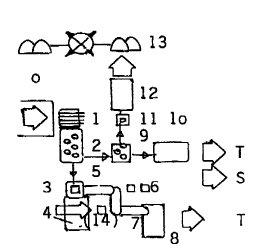
Part 1. Facility Section On Location for Dry Residues


Unlike processes and facilities used up to this time, it is the object of
the proposed process for reducing hitherto unusable dry residues from
10 rubbish from domestic waste and from industrial waste similar to domestic
waste, which remain after separation of paper, glass, plastics, biological
waste and after installation of the clearance stage "Recyclinghof" for
detoxification and removal of bulky material from the rubbish, to separate
residual tailings and several reusable fractions which represent a rather large
15 and easily useable residue fraction and waste fraction from the whole
supplied residue, by properly designing the first facility already on location.


The tailings are dumped hereby over the delivery ramp (0) with
appropriate difference in elevation into the feed funnel of a mobile drum
20 screen (2) with a stone screen attachment (1) having a lateral separation of
150 mm and a screen aperture of 25 - 40 mm.


Whereas the fine fraction is conveyed to a processing rail (9 - 13),
depending on the quality to be used as cover for waste dumps or as


CA 02228911 1998-02-06


landscaping compost, the discharged coarse fraction is dumped onto an
inclined conveyor (5) oriented transversely to the discharge. An overhead
belt magnet separator (3) is placed before the inclined conveyor (5) for
separating ferrous metals (and entrained plastic foils) into a container (4) for
5 ferrous metals - if desired, with the addition of air separators (14) for
separating the plastic foils.


At the end of the inclined conveyor (5), the waste material is inspected
on a sorting table (6) for contaminants, removing those materials which
10 alleviate subsequent process flows, and also removing those materials with
adhering dirt which do not hinder utilization on location (e.g. rims, broken
glass, textiles).


An inclined conveyor 2 (7), on which the residue mass flow is
15 conveyed, runs into the coarse fraction container with a compaction (8)
suitable for transport and particularly adapted to facilitate rail transport (40
tons per car = 13 tons max. per ACTS-compatible container).


The fine fraction (9 - 13) is guided through a small drum screen (9)
20 with a mesh size of 10 - 15 mm for separating the coarser middle fraction,

with the middle fraction conveyed to a middle fraction container (10). The fine
fraction residue flow is directed once more over a metal or induction
separator (11) before being shipped in a truck-compatible container (12) to a
proximate intensive rotting stack (13) located, for example, at existing or


. . CA 02228911 1998-02-06


former waste dumps or at a similar transfer point, where the residue is used
locally as cover or landscaping material. Light plastic materials are separated
from the ferrous metals with the help of an air separator (14).


This combination reduces the tailings by more than 40% of the prior
delivery weight, the biogenic fraction is used on location, secondary raw
materials suitable for local use are immediately conveyed to raw material
processors. Only the tailings are shipped to a stationary facility for further
processing. The stationary facility can essentially be located at any distance.

Part 2. Facility Section Stationary Dry Processing Portion


The residue - considered screen overflow - is dumped from the
container onto the discharge surface (15)7 is then - after a brief visual control
15 - inspected by sorting personnel for problematic materials, bulky
contaminants such as carpet composite1 ... and then discharged into the flat
bunker (16). The flat bunker (16) is provided with a ventilation system with air
ducts which are connected to a bio-filter (20).


An inclined conveyor (17) runs from the bunker upwards in elevation to

a sorting stage (21); an air separator (18) conveys light materials with a large
surface area, in particular plastic foils, to a plastic film container (19); on top,
blown-in air is extracted through a biofilter (20) by suction. In addition to the
plastic foil air separation, 4 additional contaminants which are not suitable for

. CA 02228911 1998-02-06


post-treatment and do not urgently require the subsequent wet shredding and
washing stage, are extracted through manual sorting or machine sorting on
the sorting stage and conveyed through discharge chutes to mobile
containers.


On the sorting stage, the residue is proportioned in height and directed
underneath an overhead plate magnet (23) for separating in particular small
metal pieces and problematic metallic materials such as batteries.


After this detoxification step, the size is reduced first. Care is taken
that a screw mill (24) does not destroy the hazardous tailings, but rather
enables water in the following washing and shredding stage to attacks the
crushed material . An inclined conveyor 2 (25) conveys the crushed residue
to wet processing (N).

Unlike conventional conditioning processes of this type, the present
process emphasizes screening, sorting and sizing as well as separation of
residue mass flows so as to properly design the process as a conditioning
step for the subsequent stages in the process chain.

Analyses at the sorting table and of the weights of the residual flows
have shown that contaminants1 such as ski boots made from glass fiber
reinforced plastic7 textiles, thermoset plastics, non-metals and non-ferrous
metals, still account for more than 20% of the residue flow. These


CA 02228911 1998-02-06


contaminants cannot be shredded into fibers in the wet shredding process.
On the other hand, the processing facilities do not require extremely pure
materials, since the processing facilities will shred and condition the materials
themselves. Also conceivable is a pre-treatment - to obtain granulate in a fine
5 shredder (Part 3/4, facility 25), before a secondary raw material (S)
conditioned in this manner is shipped to the user.


Part 3/4 Facility Section Stationary, Wet Treatment Portion Plus
Additional Conditioning for Use


The visually post-inspected (26) residue flow is conveyed to a
p~lper
di&~odging tool 1 (27) to be used for shredding reinforced fibers as well as forwashing and dislodging of dirt adhering those materials (plastics, metals, ... )which cannot be separated into fibers. Consequently, a shredder wheel for
15 fibers is an important component and selected from a product line of
pu Ipcr S
di~odging tool6. The most important element for aqueous separation of
materials is the special coil with a 3 mm fiber hole bottom perforation and a
light fraction discharge system (311 32) and a heavy fraction discharge 1 (28)
with a double material lock.

The heavy fraction lock is connected to a recess in the inclined bottom
of the trough, wherein mainly the heavy parts like rocks7 porcelain, ceramics,
small metallic pieces and glass are mixed and then separated by centrifugal
forces. When the upper lock gate is closed and the lower lock gate is


. CA 02228911 1998-02-06


opened, the heavy fraction is dumped into a mobile container and conveyed
for dewatering and further processing.


The sludge fraction is shredded again and pumped with the help of an
5 efficient pumping station via a hydrocyclone 1 (29) to the fiber sludge
container 1 positioned low (30), and from there to the compact sludge
treatment unit 1 (33) which includes a flocculation and dewatering function.
The process water is pumped back with suitable pumps (34), and the fiber
sludge cake with about 30% dry solid upon discharge is first composted (K)
10 under steam for killing germs, fungus7 viruses and spores, then turned over
and strained of residues until the sludge is ready for sale (537 54, 55).
Optionally (37), the fiber sludge cake can be use to produce a substrate for
cultivating mushrooms. The granulate residue from the hydrocyclone, on the
other hand, is conveyed to the recycling process for construction debris (BR).

The biogas production (B) is available as an option only with excellent
fermentation test parameters, followed by condensing or discharging of the
fermented suspension fluid which is the major constituent of the wet
fermentation process.

The light fraction is treated by discharging the light fraction either
through light fraction strainers or through the open heavy particle lock after a
second rinse with 5000 liters/ 4% dry solid directly into the light fraction
container 1 (32) in the lower position - the first shredding and discharge


CA 02228911 1998-02-06


process was carried out with 10000 liters and about 5% dry solid. The
strained material is removed from the strainings basket (31) by lifting7 rotating
and opening at the option Second Rinse, and conveyed to a mobile container
for dewatering (45). The option Discharge of Upper Light Fraction is carried
out with the system component LOHSE - wet waste dislodging unit, German
Patent No. P 4235197-27 by a skimming process.


The substances which can produce fine strainings from waste water
treatment plants, are dissolved in a similar manner. Prior removal of
10 contaminants by a dry method is here not required.


The fine strainings which show, as demonstrated by the analysis
commissioned by the applicant, a more than an order of magnitude
improvement in heavy metal contamination as compared to the sludge from
15 the same facility, are conveyed from the silo supplying the fine strainings (39)
to the inclined conveyor 2 (40) and moved to the second material dislodging
line next to the dry treated material (41).


The heavy particle discharge 2 (42), hydrocyclone 2 (43), fiber sludge
20 intermediate container 2 (44), strainer basket 2 (46) and the sludge treatment
compacting unit 2 (47) as well as the sludge cake discharge 2 (48) and the
sludge utilization option Mushroom Substrate (49) are constructed as a mirror
image of the unit for the dry-fed material. Designed in the same manner are
air separators for separating glass (54) if construction debris (BR) is supplied,

CA 02228911 1998-02-06


and the option for a simple biogas plant (B), depending on the feed stock.
Commonly required post-treatment steps on both rails are the facility light
fraction fine shredder (50) after the light fraction is discharged from the
container, and dewatering of the light fraction (45). For further conditioning,
5 these steps are followed by an optional hydrocyclone (31 ) for plastics, and
thereafter already by the processing steps of the facility section Utilization
(part 4). Among those steps is the induction separator for non-ferrous metals
(52) and the removal in the form of conditioned secondary raw material (S).
Similarly, the injection of steam (54), turning over the stack (54) and the
10 straining process (55) for manufacturing finished composts (K).


Commonly used is also the process water return (R) of a modular
facility unit of part 3/4. Pumps (34) return process water from the sludge
treatment compacting units 1 and 2 into the process water tank (36). The tank
15 is able to hold the entire quantity of process water contained in the loop for
starting the operation and includes a supply line for fresh water (F), with the
sediments discharged at the lower end of the tank which extends upwardly to
the double lock and is shaped like a cone. After the upper lock is latched and
the lower lock is opened, a mass of the sediment of 0.5 m3 flows at each
20 dissolution step from the double lock into a pre-filtration filter bag unit (38).


Cleaned process water is returned to the process water tank. 10,000
liters and subsequently 5,000 liters of process water, and also the 1,500 liters
of added fresh water are withdrawn at each dislodging step. The process


CA 02228911 1998-02-06


water loop can be fully balanced for a compost bed with percolation tank in
interconnected facilities, except for the contribution from evaporated and
condensecl water. All the process water is carried in the waste water loop. A
process water bypass for protecting the return and pump loop should
5 nevertheless be provided, also intermediate tanks with overhead water
feed (ZW).


The remaining dry-fed materials, such as screen residues, soiled
plastics and screened refuse, are treated similarly to the materials on the dry
10 treatment rail; in the case of wet waste materials, treatment is analogous to
the wet treatment rail. Fermentation tests suggest the implementation of the
additional option biogas plant or conveyance to a rotting (faulschlamm) tower
(B).
The processing path for fiber sludge compost is linked to intermixing
15 with shredded bark. The processing path of the remaining secondary raw
materials (S) is selected such that the secondary raw materials are clean
when they leave the facility and can be returned to the material cycle either
immediately or after a brief treatment in the user facilities. Mixed plastics
which cannot be separated further following the hydrocyclone for plastics, are
20 shipped out for recovering raw materials. Hazardous materials are handed
over to an authorized waste disposal unit.


CA 02228911 1998-02-06


0 Discharge ramp/ transfer station
Rock grate
2 Large drum screen, mobile
3 Overhead belt magnet separator
4 Ferrous metal container
5 Inclined conveyor belt 1
6 Control screening for contaminants
7 Inclined conveyor belt 2
8 Coarse fraction container
9 Small drum screen, mobile
10 Middle fraction container
1 1 Metal induction separator
12 Fine fraction container
13 Rotting stack
14 Air separator
T Transport to section 2
S Secondary raw material processing
15 Discharge surface
16 Flat bunker
17 Inclined conveyor belt 1
18 Air separator
19 Plastic Film container


CA 02228911 1998-02-06


20 Biofilter with exhaust channels
21 Sorting stage with 5 contaminant
22 Containers and discharge chutes
23 Height proportioning of residue flow and
separation of small ferrous particles
24 Screw mill
25 Inclined conveyor belt 2
Secondary raw materials
To section 3/ wet treatment stage
26 Inclined feed conveyor - visual and sensor control
p u L ?~R
27 Matcrio~ di~lodging unit 1
28 Heavy particle discharge 1 (container)
29 Hydrocyclone 1
30 Fiber sludge intermediate container 1
31 Strainings basket 1 and strainings discharge
32 Light fraction intermediate container 1
33 Sludge treatment compacting unit 1
34 Process water pump and thick matter pump
35 Fiber sludge cake discharge 1 (container)
36 Process water tank
37 Sludge recovering option substrate for cultivating mushrooms
38 Filter bag pre-filtering unit

CA 02228911 1998-02-06


39 Fine strainings feed silo
40 Inclined conveyor belt 2
?u.~ P~
41 M~tt~ri- l~ di~l~61ging unit 2
42 Heavy fraction discharge 2 (container)
43 Hydrocyclone 2
44 Fiber sludge intermediate container 2
45 Light fraction dewatering after discharge
46 Strainings basket 2
47 Sludge treatment compacting unit 2
48 Fiber sludge cake discharge 2 (container)
49 Sludge recovering option substrate for cultivating mushrooms
50 Light fraction fine shredder
51 Recovering option hydrocyclone for plastics
52 Induction separator for non-ferrous metals
53 Rotting stacks for killing germs with steam
54 Stack turner and bark mixer
55 Compost strainer drum similar to 9, Part 1
56 Air separator
K Marketable composts
S Secondary raw materials
B Option biogas plant or rotting container
BR Construction debris recycling

Representative Drawing
A single figure which represents the drawing illustrating the invention.
Administrative Status

For a clearer understanding of the status of the application/patent presented on this page, the site Disclaimer , as well as the definitions for Patent , Administrative Status , Maintenance Fee  and Payment History  should be consulted.

Administrative Status

Title Date
Forecasted Issue Date Unavailable
(86) PCT Filing Date 1996-06-07
(87) PCT Publication Date 1996-12-27
(85) National Entry 1998-02-06
Examination Requested 2003-06-04
Dead Application 2006-06-07

Abandonment History

Abandonment Date Reason Reinstatement Date
2005-06-07 FAILURE TO PAY APPLICATION MAINTENANCE FEE
2005-08-22 R30(2) - Failure to Respond
2005-08-22 R29 - Failure to Respond

Payment History

Fee Type Anniversary Year Due Date Amount Paid Paid Date
Application Fee $150.00 1998-02-06
Maintenance Fee - Application - New Act 2 1998-06-08 $50.00 1998-05-27
Maintenance Fee - Application - New Act 3 1999-06-07 $100.00 1999-06-07
Maintenance Fee - Application - New Act 4 2000-06-07 $100.00 2000-06-07
Maintenance Fee - Application - New Act 5 2001-06-07 $150.00 2001-05-24
Maintenance Fee - Application - New Act 6 2002-06-07 $150.00 2002-06-04
Maintenance Fee - Application - New Act 7 2003-06-09 $150.00 2003-05-30
Request for Examination $400.00 2003-06-04
Maintenance Fee - Application - New Act 8 2004-06-07 $200.00 2004-06-04
Owners on Record

Note: Records showing the ownership history in alphabetical order.

Current Owners on Record
FELBER, WALTER
Past Owners on Record
None
Past Owners that do not appear in the "Owners on Record" listing will appear in other documentation within the application.
Documents

To view selected files, please enter reCAPTCHA code :


To view images, click a link in the Document Description column. To download the documents, select one or more checkboxes in the first column and then click the "Download Selected in PDF format (Zip Archive)" or the "Download Selected as Single PDF" button.

List of published and non-published patent-specific documents on the CPD .

If you have any difficulty accessing content, you can call the Client Service Centre at 1-866-997-1936 or send them an e-mail at CIPO Client Service Centre.


Document
Description 
Date
(yyyy-mm-dd) 
Number of pages   Size of Image (KB) 
Representative Drawing 1998-05-19 1 5
Cover Page 1998-05-19 2 77
Abstract 1998-02-06 1 28
Description 1998-02-06 12 356
Claims 1998-02-06 7 217
Drawings 1998-02-06 3 43
Prosecution-Amendment 2005-02-21 2 54
Assignment 1998-02-06 2 95
PCT 1998-02-06 14 460
Fees 2003-05-30 1 36
Prosecution-Amendment 2003-06-04 1 40
Fees 1998-05-27 1 30
Fees 1999-06-07 1 38
Fees 2000-06-07 1 41
Fees 2004-06-04 1 43