Note: Descriptions are shown in the official language in which they were submitted.
CA 02238395 1998-OS-22
WO 98/!2999 PCT/US97/16836
-1-
SYSTEM AND METHOD FOR APPLYING THERMAL ENERGY TO TISSUE
BACKGROUND OF THE INVENTION
Field of the Invezition
The invention relates to a device for heating fluid in a
cavity to thermally treat body tissue. More particularly, the
present invention relates to an expandable device filled with
a conductive fluid and having a bipolar electrode assembly to
heat the conductive fluid.
Description of Related Art
Application of thermal energy has been used for same time
to treat body tissue. One method of controlled application of
thermal energy involves the use of a balloon or similar bladder
filled with heated fluid. The bladder is placed against the
tissue to be treated, and the heat from the fluid passes
through the walls of the bladder and into the tissue.
Application of thermal energy with fluid-filled balloons
has been of particular use in treating tissue in body cavities
of animals, including humans. For example, balloons filled
with heated fluid have been used to effect cauterization of
a
uterine endometrium.
A method is known for effecting necrosis of the
endometrium by inserting a distensible bladder into the uterus.
The distensible bladder is inflated to a predetermined pressure
with a fluid so that the distensible bladder is in contact with
substantially all of the tissue lining for which necrosis is
desired. The fluid is heated to a temperature sufficient to
ablate the tissue lining. The temperature and pressure of the
fluid is controlled by means connected to the distensible
bladder . The bladder is maintained inf laced with the f luid
at
a temperature for a period of time sufficient to effect
necrosis of the endometrium.
Early methods for heated-balloon therapy required the
fluid to be preheated outside the body, and then pumped through
conduits into the balloon or other bladder. However, such
methods may cause heat to build up around the conduits as they
CA 02238395 2005-03-14
-2-
pass into the body cavity, which may cause unwanted heating of body tissue
adjacent
to the entry into the body cavity. Another previous method for heated-balloon
therapy
involved positioning a heating element coil in the balloon, and causing an
electrical
current to pass through the coil, thereby heating the coil and the surrounding
fluid.
Consequently, there is a need to improve heated fluid systems to provide rapid
and uniform heating while at the same time allowing a user to monitor and
control the
fluid temperature. The present invention satisfies these needs.
SUMMARY OF THE INVENTION
Briefly and in general terms, the present invention provides an apparatus,
system, and method for heating fluid in a cavity. More particularly, the
present
invention is a device and method for inducing an electrical current in a
conductive
fluid in a cavity, and thereby heating the conductive fluid.
Briefly and in general terms, the present invention provides an apparatus,
system, and method for applying heat to body tissue, such as for endometrial
ablation.
The apparatus provides for heating of an inflation medium within a distensible
bladder positioned adjacent to the tissue to be treated. The invention has
particular
application in providing a safe and efficacious method for ablating the
endometrium
of the uterus. The present invention thus provides a relatively inexpensive
and easy
method to treat menorrhagia in women.
More particularly, the invention provides an apparatus for treating tissue at
a
selected operation site, the apparatus comprising:
a bladder; and
a bipolar electrode assembly positioned within the bladder, said bipolar
electrode assembly including an active electrode and a shield configured to
prevent
the active electrode from contacting the bladder.
In another aspect, there is provided an apparatus for treating tissue at a
selected operation site, the apparatus comprising:
a bladder; and
CA 02238395 2005-03-14
-2a-
a bipolar electrode assembly positioned within the bladder, said bipolar
electrode assembly including an active electrode and a return electrode,
wherein the
active electrode has an effective area, and the return electrode has an
effective area
different from the active electrode effective areas,
wherein the return electrode effective area is at least twice as large as the
active electrode effective area,
wherein the active electrode is at a distal tip of the shaft, the return
electrode is
proximal to the return electrode on the shaft, and further comprising an
insulator
between the active electrode and return electrode, and
wherein the return electrode is coaxial with the active electrode.
In another aspect, there is provided an apparatus for delivering controlled
heat
to a selected operation site, the apparatus comprising:
an expandable device, wherein the expandable device has a delivery
configuration and an expanded configuration, wherein the expandable device may
be
transformed from the delivery configuration to the expanded configuration and
subsequently returned to the delivery configuration;
a shaft having a distal end disposed within the expandable device, said shaft
configured for movement within the expandable device, wherein the shaft passes
through an opening in the expandable device, and said shaft is configured for
pivotal
movement within said opening; and
an electrode assembly at the shaft distal end.
In yet another aspect, there is provided an apparatus for delivering
controlled
heat to a selected operation site, the apparatus comprising:
a shaft having a distal end;
an electrode assembly at the shaft distal end, said electrode assembly
comprising at least one active electrode and at least one return electrode;
and
a mechanically expandable device for the shaft distal end, wherein the
mechanically expandable device has a delivery configuration and an expanded
configuration,
CA 02238395 2005-03-14
-2b-
wherein the mechanically expandable device may be transformed from the
delivery configuration to the expanded configuration and subsequently returned
to the
delivery configuration, the mechanical device in the expanded configuration
defining
a space therein, wherein at least one of said electrodes is positioned within
said
defined space,
wherein the mechanically expandable device comprises an expandable cage,
and
wherein at least one of said electrodes is disposed on the mechanically
expandable device.
In another aspect, there is provided an apparatus for delivering controlled
heat
to a selected operation site, the apparatus comprising:
a shaft having a distal end;
a mechanically expandable device at the shaft distal end, wherein the
mechanically expandable device has a delivery configuration and an expanded
configuration; and
an electrode assembly at the shaft distal end, said electrode assembly
comprising at least one active electrode and a plurality of return electrodes,
wherein
said return electrodes are disposed on the mechanically expandable device.
In one embodiment, the invention includes an apparatus for treating tissue at
a
selected operation site, including a distensible bladder with an electrode
assembly
positioned therein, which is preferably a bipolar electrode assembly including
one or
more active electrodes and one or more return electrodes. The bladder is
filled with a
conductive fluid such as a saline solution. The apparatus may include a shield
that
prevents one or both electrodes from contacting the bladder. The shield may be
a part
of one of the electrodes.
CA 02238395 1998-OS-22
WO 98/12999 PCT/US97116836
-3-
The apparatus may be part of a system including a control
unit providing electrical energy, such as RF energy, to the
electrode. The control unit may monitor the fluid temperature,
either through the use of temperature sensors or by monitoring
the impedance across the bipolar electrodes, and adjust power
to maintain the fluid temperature within a desired range. The
control unit may have a display for showing fluid temperature
and/or pressure, and may include an alarm for indicating an
undesired level of fluid temperature and/or pressure. The
control unit may also include a multiplexes for independently
controlling the delivery of power to individual electrodes in -
the electrode assembly.
In a further embodiment, the inner surface of the bladder
may be conductive so that it acts as an electrode. The bladder
may have a plurality of electrodes on its inner surface, with
individual electrodes independently controlled by the control
unit.
In a further embodiment, the apparatus uses an expandable
cage instead of a distensible bladder. The expandable cage may
be conductive and act as one or more electrodes of the
electrode assembly.
In another embodiment, the invention is a method of
treating tissue using a surgical device, including an
expandable device and a bipolar electrode assembly with at
least one active electrode and at least one return electrode,
including the steps of: introducing the distal end of the
surgical device into a selected operation site; expanding the
expandable device; filling the expandable device with a
conductive saline solution; and applying output power to the
bipolar electrode assembly to heat the conductive fluid. The
method may include the further steps of monitoring the fluid
temperature, and controlling the output power to the electrode
assembly to maintain the temperature of the conductive fluid in
a desired temperature range. The temperature may be determined
by monitoring the impedance between the active electrode and
return electrode.
In a further embodiment, the electrode assembly is used
. not only to heat the conductive fluid but also to treat
CA 02238395 1998-OS-22
WO 98/12999 PCTlUS97/16836
-4-
specifically targeted tissue. In such a method, the electrode
assembly is preferably movable within the expandable device,
and can be positioned adjacent specifically targeted tissue.
Such a method is of particular use with an expandable device
comprising an expandable cage.
Other features and advantages of the present invention
will become more apparent from the following detailed
description of the invention when taken in conjunction with the
accompanying drawings.
B_F~IEF DESCRIPTION OF THE DRAWINGS
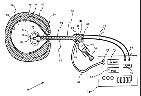
FIGURE 1 depicts, in partial section, a system according
to the present invention, including a control unit and
treatment catheter having a distensible bladder, with the
distensible bladder inserted into and inflated within the
uterus of a patient.
FIG. 2 is a side view, in partial section, of a heated
bladder device according to a preferred embodiment of the
invention.
FIG. 3 is a side view, in partial section, of a heated
bladder device according to a further embodiment of the
invention.
FIG. 4 is a side view of an electrode assembly according
to another embodiment of the invention.
FIG. 5 is a side view of an electrode assembly according
to another embodiment of the invention.
FIG. 6 is a side view, in partial section, of a heated
bladder device according to a further embodiment of the
invention.
CA 02238395 1998-OS-22
WO 98/12999 PCT/U897/16836
-5-
FIG. 7 is a side view, in partial section, of a heated
bladder device having a conductive inner surface according to
an embodiment of the invention.
FIG. 8 is a top view, in partial section, of a heated
bladder device having multiple electrodes on its inner surface
according to another embodiment of the invention.
FIG. 9a is a side view, in partial section, of a heated
device with an expandable cage in a collapsed, delivery
configuration.
FIG. 9b is a side view of the device of FIG. 9a, showing
the expandable cage in its deployed, expanded configuration.
FIG. 9c is a side view of the device of FIGS. 9a and 9b,
with the electrode assembly and catheter moved within the
expandable cage.
FIG. 10 is a side view, in partial section, of a further
embodiment of the invention.
FIG . 11 is a side view, in section, of a pumping electrode
according to an embodiment of the invention.
FIG. 12 is a side view, in partial section, of an
electrode and nozzle according to an embodiment of the
invention.
DETAILED DESCRIPTION OF THE PREFERRED EMBODIMENTS
The present invention is depicted in FIGS . 1-11 for use in
. body cavities, including use in ablating the endometrial lining
of a patient's uterus. However, the present invention is not
limited to use in the uterus, and may be applied to techniques
for thermal treatment of a variety of tissue, including the
treatment of tissue within a variety of body cavities such as
the bladder, the gall bladder, portions of the gastrointestinal
CA 02238395 2005-03-14
-6-
tract, the heart, and other body cavities. The invention may be used in a
variety of
procedures, including thermal treatment of hemorrhoids, intestinal walls, the
lining of
the rectum, the lining of the bladder, etc. Moreover, the invention may also
be used
for heating fluid in a variety of applications where controlled application of
heat is
desired, and not just for the treatment of tissue.
Referring now to FIG. l, in one preferred embodiment the system 10 of the
invention comprises a catheter 12 and a control unit 14. The catheter 12
includes a
generally elongated shaft 16 having a distensible bladder 18 and electrode
assembly
20 at its distal end 22. The electrode assembly 20 is positioned in and
surrounded by
the distensible bladder 18. The electrode assembly 20 comprises an active
electrode
24 and a return electrode 26, and may be of the type shown and described in
pending
U.S. Patent Application Ser. No. 08/702,512 entitled "An Electrosurgical
Instrument," now U.S. Patent No. 6,004,319. Alternatively, the electrode
assembly 20
of the current invention may have greater spacing between the active electrode
24 and
return electrode 26, thereby increasing the minimum distance for current to
must pass
between the active electrode 24 and return electrode 26. Thus, thermal
distribution
may be improved.
In the embodiment of FIG. 1, the active electrode 24 and return electrode 26
are in electrical contact with electrical connectors 28, 30 that are in turn
in electrical
contact with the control unit 14. In the embodiment of FIG. 1, the electrical
connectors 28, 30 are located at the proximal end 32 of the catheter shaft 16,
and are
removably secured to the control unit 14 via cables 34. The catheter shaft
proximal
end 32 has a handle 36 by which a user may grasp the device.
FIG. 1 shows the distal end 22 of the instrument shaft 16 placed in a body
cavity, which in the embodiment shown is a human uterus 40. The bladder 18 is
inflated with a conductive fluid 42, such as a saline solution, to a pressure
sufficient
to ensure firm contact with the endometrial tissue layer 44 on the interior
uterine
surface 46.
CA 02238395 1998-OS-22
WO 98112999 PCT/US97/16836
Electrical power is provided to the electrode assembly 20
to cause current to flow between the active electrode 24 and
return electrode 26 and through the conductive fluid 42,
thereby heating the conductive fluid 42. The method provides
for heating the conductive fluid 42 within the distensible
bladder 18 to a desired temperature, and maintaining the
temperature and pressure within the distensible bladder 18 for
a desired time interval. Afterwards, the distensible bladder
18 is deflated and the catheter shaft 16, including the
distensible bladder 18 and electrode assembly 20, is removed
from the patient's uterus 40.
The bladder 18 must be capable of withstanding high
temperatures without rupturing, and preferably have good heat
transfer characteristics to provide efficient heating action.
A distensible bladder of a heat-curing rubber, such as latex
rubber, has been found satisfactory in similar applications.
The bladder may be formed of elastic or inelastic materials.
Inflation of the bladder 18 may be accomplished through
various ways. In the embodiment of FIG. 1, conductive fluid 42
is introduced into the bladder 18 using a fluid source; such as
a syringe 48, in fluid contact with the bladder 18 via a fluid
line 50 and fluid fill port 52 that leads to the bladder 18.
Manipulation of the syringe 48, by depressing a plunger 54,
causes conductive fluid 42 to be introduced into the
distensible bladder 18, forcing the distensible bladder 18 to
expand into contact with the endometrial tissue layer 44 of the
uterus 40. The conductive fluid 42 is also directed along
flexible tubing 56 to the control unit 14, where the pressure
is measured by a sensor such as a pressure transducer 58. All
parts of the fluid path, including the bladder 18, fluid line
50, and flexible tubing 56, are in fluid communication, thus
providing constant fluid pressure within the entire fluid
system and allowing measurement of bladder pressure by
monitoring the pressure within the flexible tubing 56. The
control unit 14 monitors the fluid pressure and shows the
pressure on a pressure display monitor 60.
In many procedures, it is desirable to monitor and
maintain the fluid pressure within a desired range, with the
CA 02238395 2005-03-14
_g_
desired pressure range depending on the particular application. The pressure
display
monitor 60 located on the control unit 14 shows the pressure to the user. If
the
pressure in the distensible bladder 18 is beyond a desired range, a warning
signal
and/or alarm 62 alerts the user that the pressure is either too low or too
high. To
adjust the pressure; the user may manually manipulate the plunger 54 of the
syringe
element 48. Alternatively, the control unit 14 may include a pump or similar
device
(not shown) in fluid contact with the bladder 18 that automatically provides
or
removes conductive fluid 42 from the bladder 18 to regulate the pressure to
maintain
the pressure within a selected range.
The control unit 14 provides power to the electrode assembly 20 via the
electrical ports 64, to which are secured the connecting cables 34 that link
the
connectors 28, 30 of the active and return electrodes 24, 26. The power
provided may
be of a variety of types and power levels. AC and/or DC power may be used,
depending on the particular use and circumstances. Radio-frequency (RF) power
has
particular application with the invention, as does pulse-width modulation.
The current flow between active and return electrodes 24, 26 heats the
conductive
fluid 42. The temperature of the fluid 42 is monitored by the control unit 14,
either
via a temperature sensor 66 positioned in the bladder 18, an impedance vs.
temperature calculation, or other means. The temperature is preferably shown
on a
temperature display 68 on the control unit. In a preferred embodiment, the
control
unit 14 compares the monitored temperature to the desired temperature and
automatically adjusts the power to compensate for temperature changes. If the
monitored temperature is above a desired range, power is reduced to allow the
fluid to
cool. If the monitored temperature is below a desired range, power is
increased to
heat the fluid. If temperature is beyond a selected range, the control unit
may activate
the alarm 62.
The control unit 14 may comprise a generator of the type described in pending
U.S. Application Ser. No. 08/642,121, filed May 2, 1996, entitled "An
Electrosurgical
Generator And System," now U.S. Patent No. 6,293,942. In a
CA 02238395 1998-OS-22
WO 98/12999 PCT/US97/16836
-9-
preferred embodiment, the Control unit 14 includes a generator
having a radio frequency (RF) power oscillator with an
electrical connection, such as a pair of output connection
ports 64, for coupling, via one or more cables 34, to the
catheter 12 and electrode assembly 20. When RF power is
applied to the electrode assembly 20, the conductive fluid 42
heats up. If the conductive fluid 42 is a saline solution such
as 0.9~ w/v, the temperature coefficient of the fluid 42 is
positive, so that the corresponding impedance coefficient is
negative. As power is applied, the impedance between the
active electrode 24 and return electrode 26 initially falls and
continues to fall with increasing dissipation of power.
If sufficient power is applied, a vapor bubble may form
about the active electrode 24. As the saline in immediate
contact with the active electrode 24 reaches its boiling point,
vapor bubbles may form on the surface of the active electrode
24 , which necessarily cause the impedance across the electrodes
24, 26 to rise. As power is further increased, the impedance
will continue to rise as the vapor bubbles enlarge to form a
vapor pocket about the active electrode 24.
As the vapor pocket begins to form about the active
electrode 24, there is an increase in the power density at the
residual electrode/saline interface. initially, there is an
exposed area of the active electrode 24 that is not covered by
the vapor bubbles. This exposed area becomes the preferred
electrical path, further stressing the interface by producing
more vapor bubbles and even higher power density. The
formation of the vapor pocket quickly becomes a runaway
condition that only reaches equilibrium once the active
electrode is completely enveloped in the vapor pocket.
Once the vapor pocket completely envelopes the active
electrode 24, the impedance rapidly increases to around 1000
. ohms, with the actual impedance value dependent upon system
variables. Power passes from the active electrode 24 to the
conductive fluid 42 via electrical discharges across the vapor
pocket. The majority of the power dissipation occurs within
this pocket, with consequent heating of the active electrode
24. The amount of energy dissipated, and the size of the vapor
CA 02238395 1998-OS-22
WO 98/12999 PCT/US97/16836
-10-
pocket, depends on the output voltage. Maintaining the vapor
pocket without destroying the active electrode requires a
delicate balance of output voltage. If it is too low, the
pocket will not be sustained. If it is too high, the electrode
assembly 20 can be destroyed. Accordingly, once the impedance
has reached a certain point indicating formation of the vapor
pocket, the power must be reduced to a selected level.
It is generally important to control, and possibly
prevent, formation of the vapor pocket about the active
electrode 24 in order to maximize the efficiency of heating the
conductive fluid. By increasing the distance between the
active electrode 24 and return electrode 26, thermal
distribution can be improved, thereby increasing the upper
limit of power delivery before the onset of vaporization. For
example, if sufficient power is applied, the vapor pocket might
create significant amounts of steam in the bladder, which can
have undesirable effects such as the creation of a large vapor
buildup at the top of the bladder that can significantly reduce
the thermal transfer efficiency. The boiling vapor pocket may
also create undesired noise. To control the formation of the
vapor pocket and the temperature of the conductive fluid, the
control unit 14 monitors the peak RF voltage appearing across
the output connection ports 64 of the control unit 14, which
corresponds to the voltage across the active electrode 24 and
return electrode 26, and rapidly reduces the delivered output
power whenever a selected peak voltage threshold is reached.
Accordingly, the control unit 14 can monitor the impedance and
control output power to prevent the formation of vapor bubbles .
This may be achieved by detecting an impedance increase that
indicates the initial formation of vapor bubbles, and rapidly
reducing power to prevent formation of a vapor pocket.
Alternatively, the control unit 14 can monitor the impedance
and control output power to form and maintain a vapor pocket. .
In the preferred embodiment shown in FIG. 2, the electrode
assembly 20 is a bipolar electrode having an active electrode
24 and a return electrode 26. However, the system would still
operate if the polarity ware reversed, i.e., if the active
electrode 24 served as a return electrode, with, the return
CA 02238395 1998-OS-22
WO 98/I2999 PCT/U897/16836
-11-
electrode serving as an active electrode. Additionally, where
AC power is used with the system, the terms "active electrode"
and "return electrode" lose their traditional
"negative/positive" meanings. For AC applications, the terms
"active" and "return" are used to refer to the electrodes
having opposing polarities. Where the electrodes have
differing sizes in AC applications, the term "active electrode"
is generally used to refer to the smaller electrode, and the
term "return electrode" is generally used to refer to the
larger electrode.
The active electrode 24 of FIG. 2 is positioned at the
extreme distal tip of the catheter shaft 16. The return
electrode 26 is proximal of and coaxial with the active
electrode 24. In the particular embodiment shown in FIG. 2,
the effective area of the return electrode 26 is substantially
greater than the effective area of the active electrode 24.
However, the effective areas of the electrodes 24, 26 may vary
significantly in different embodiments, depending on the
particular electrode assembly. For example, in various
embodiments of the invention, the active and return electrodes
may have substantially equal areas,' or the active electrode may
be substantially larger than the return electrode.
In FIG. 2, the active and return electrodes 24, 26 are
separated by an insulator 70, such as a ceramic material. As
shown roughly in FIG. 2, when power is applied to the electrode
assembly 20, current flows from the active electrode 24,
through the conductive fluid 42, and into the return electrode
26. The interaction of the current with the conductive fluid
42 heats the fluid 42.
In addition to heating the fluid 42, the interaction of
the current with the conductive fluid 42 can also create a
magnetohydrodynamic effect that causes stirring of the fluid
within the bladder 18. This fluid stirring can be relatively
intense, depending on the particular electrode configuration
and the type and level of electrical power provided. The fluid
stirring is particularly intense when RF power or pulse-width
modulation is used. The magnetohydrodynamic stirring can be
beneficial in helping to maintain relatively constant fluid
CA 02238395 1998-OS-22
WO 98/12999 PCT/US97/i6836
-12-
temperatures throughout the bladder 18.
An additional advantage of the invention is the ability to
determine the temperature of the conductive fluid 42 using
impedance/resistivity. Many conductive fluids have
resistivities/impedances that are temperature dependent, so the
temperature may be calculated from resistivity/impedance. For
example, saline solution is a negative-temperature-coefficient
material (i.e., it has a positive thermal coefficient of
conductivity, which is a negative thermal coefficient of
impedance), so that a small change in temperature causes a
large corresponding change in the impedance/resistivity of the
saline solution. Because the impedance/resistivity are
temperature dependent, the temperature of the conductive fluid
42 in the bladder 18 can be accurately determined by monitoring
the impedance/resistivity between the active and return
electrodes 24, 26.
An advantage of using the impedance/resistivity between
the electrodes 24, 26 is that the resulting temperature is
based upon the path of the electrical current, which flows
through all the conductive fluid 42 within the distensible
bladder 18. The current path between the two electrodes 24, 26
passes, at varying levels, through the entire body of
conductive fluid 42 in the bladder 18. Accordingly, rather
than giving a temperature measurement of just an isolated
position in the fluid, as would be the case with a conventional
temperature sensor, an impedance-based temperature
determination gives a more accurate measurement of overall
fluid temperatures in the bladder 18..
As shown in FIG. 2, the catheter may include one or more
temperature sensors 66 for monitoring temperature within the
conductive fluid 42. These temperature sensors 66 may be in
lieu of or in addition to the impedance-based temperature
measurement. The temperature sensors may employ a variety of
sensor types and techniques, including thermocouples,
thermistors, RTD (resistance temperature device), curie-point
method, photofluorescent decay, etc. The particular selection
of temperature sensor may depend on the particular application.
For example, because thermocouples can be sensitive to RF
CA 02238395 1998-OS-22
WO 98/12999 PCT/CJ597/16836
-13-
noise, another type of temperature sensor may be desirable
for
applications where the control unit generates RF energy for
the
electrode assembly.
The control unit 14 may use the impedance-based
temperature measurement, the measurement from the temperature
sensors 66, or a combination thereof to regulate the power
delivered to the electrode assembly and/or the temperature
shown on the temperature display 68. When the fluid
temperature is too high, the power can be reduced. If the
fluid temperature is too low, the power can be increased.
The catheter 12 may include a shield 72 that generally
surrounds the electrode assembly 20. The shield 72 prevents
the electrode assembly 20, and particularly the active
electrode 24, from contacting and/or damaging the bladder wall
74. In the embodiment of FIG. 2, the shield 72 has a plurality
of openings 76 which allow conductive fluid 42, as well as
electrical current, to pass freely therethrough. In
alternative embodiments, the shield 72 may comprise a cage
or
mesh assembly.
In the embodiment shown in FIG. 2, the shield 72 surrounds
both the active electrode 24 and return electrode 26. However,
depending on the particular application and power involved,
the
shield 72 may surround either the active electrode 24 or the
return electrode 26, but not necessarily both. Due to the size
difference between the active electrode 24 and return electrode
26, the active electrode 24 generally is much hotter than the
return electrode 26. Thus, contact between the bladder wall
74
and the return electrode 26 may result in no damage to the
bladder wall 74, while contact between the active electrode
24
3 0 and the bladder wall 74 at the same power input might cause
severe damage to the bladder wall 74. Accordingly, protecting
the bladder 18 from contact with the return electrode 24 may
not always be necessary, even in situations where the bladder
wall 74 must be protected from contact with the active
electrode 24.
In another embodiment of the invention, the shield 72 acts
as the return electrode 26, as shown in FIG. 3. The inner
surface 78 of the shield 72 is conductive and acts as the
CA 02238395 1998-OS-22
WO 98!12999 PCTJUS97l16836
-14- '
return electrode 26, while the shield outer surface 80 is non-
conductive. However, the system would also operate if the
outer surface 80 of the shield were conductive. Because the -
return electrode 26 is so much larger in effective area than
the active electrodes 24a-c, the power is largely dissipated
across the return electrode 26, i.e., across the shield 72.
Accordingly, heat and energy buildup is much less than in the
active electrode 24a-c and, depending on the particular
electrode configuration, bladder, and power involved, the
return electrode 26/shield 72 may be able to contact the
bladder wall 74 during a procedure without harming the wall 74.
Note that the invention is not limited to the shield being
a return electrode. For example, in the example of FIG. 3, the
shield 72 could serve as an active electrode, with the
(formerly active) electrodes 24a-c serving as return
electrodes. Additionally, the invention is not limited to a
single active electrode or a single return electrode. Almost
any number of active electrodes and return electrodes may be
used. Additionally, the number of active electrodes does not
have to equal the number of return electrodes. For example, in
the embodiment of FIG. 3, there are three active electrodes
24a, 24b, 24c, but only one return electrode 26. The active
electrodes 24a, 24b, 24c may be individually controlled, so
that power is applied to individual or groups of active
electrodes as desired.
FIG. 4 shows another embodiment of a catheter 12 with
multiple active electrodes 24a-c, but also having multiple
return electrodes 26a-c. Three active electrodes 24a-c are
located on a first side 82 of the catheter shaft 16, and three
return electrodes 26a-c are located on a second side 84. The
electrodes 24a-c, 26a-c are separated by an insulating material
70. In such an embodiment, all electrodes 24a-c, 26a-c may be
activated simultaneously. Alternatively, the electrodes 24a-c,
26a-c may be activated in sets. For example, if the system
desired the fluid in the distal portion of the bladder to have
greater heat, just the most distal active electrode 24a and
return electrode 2&a might be activated.
CA 02238395 1998-OS-22
WO 98/12999 PCT/US97/16836
-15-
FIG. 5 shows another embodiment of a catheter 12 having
multiple active electrodes 24a-c and return electrodes 26a-c,
but with the electrodes 24a-c, 26a-c coaxially positioned in
alternating order on the catheter shaft 16 and separated by an
insulating material 70. As with the embodiment of FIG. 4, the
electrodes 24a-c, 26a-c are preferably capable of independent
activation, so that the application of energy can be controlled
with greater accuracy.
Individually controlled electrodes 24a-c, 26a-c can be
used in combination with a control unit having a multiplexer
used to chop the power output to enhance the connective
stirring effect induced by the temperature gradients within the
conductive fluid. The control unit can control the output
power to individual electrodes 24a-c, 26a-c to induce a
selected fluid flow within the bladder 18. For example, by
independently and sequentially activating matched or unmatched
pairs of electrodes, a selected flow can be induced in the
bladder. FIG. 6 shows sequential activation of the most distal
active electrode 24a and return electrode 26a, then the middle
active electrode 24b and return electrode 26b, and then the
most proximal active electrode 24c and return electrode 26c, a
generally circulating flow can be induced that causes the
conductive fluid 42 to flow along the catheter shaft 16 in a
proximal direction, then flows along the bladder wall 74 in a
.distal direction to complete the flow pattern shown in FIG. 6.
An advantage to controlling the fluid flow is that high-
temperature fluid can be concentrated in selected areas of the
bladder 18. For example, in the example shown in FIG. 6, the
fluid passing proximal along the catheter shaft 16 receives the
greatest heat due to its proximity to the electrodes 24a-c,
26a-c. Conversely, as the fluid passes distally along the
bladder wall 74, it cools. Such a flow has the desirable
_ effect of concentrating the hottest fluid at the bladder
proximal end 86, with cooler fluid at the bladder distal end
88. In endometrial ablation procedures, greater heat is
generally required to treat thicker portions of the endometrial
layer 44. As shown in FIG. 6, the thickest portions of the
endometrial layer are closest to the cervix 90, i.e., are
CA 02238395 1998-OS-22
WO 98/I2999 PCT/U897J16836
-16-
adjacent to the proximal end 86 of the distensible bladder 18,
where the hottest conductive fluid is directed. Conversely,
the thinnest portions of the endometrial layer are at the back
of the uterus 92, which is adjacent the distal portion 88 of
the bladder 18 with the coolest conductive fluid.
FIG. 7 shows a further embodiment of the invention,
wherein the inner surface 94 of the distensible bladder 18
functions as the return electrode, and the active electrode 24
is positioned at the end of the catheter shaft 16. The bladder
18 itself may be formed of a conductive material.
Alternatively, the bladder may be generally non-conductive, but
may have a conductive inner surface 94. For examz~la. a
conductive material may be deposited on the inside of the
bladder 18 to form a conductive inner surface 94. An example
would be a sputter deposition of a conductive metal such as
gold or silver.
When power is applied to the device, electrical current
passes between the active electrode 24 and the conductive inner
surface 94, via the conductive fluid 42. The conductive fluid
is heated in the process.
If the conductive inner surface 94 of the bladder 18 is a
positive-temperature-coefficient material (i.e., has a negative
thermal coefficient of conductivity), such as gold or silver,
the resistivity/impedance of the inner surface 94 increases as
the temperature increases. Thus, current will necessarily be
drawn more readily to a cooler area 96 of the bladder wall 74.
Such behavior is particularly advantageous for ablating tissue,
such as the endometrial lining 44 of the uterus 40. As tissue
is ablated, it looses much of its ability to absorb heat from
the adjacent bladder wall 74. Accordingly, a bladder wall
portion 96 overlying non-ablated tissue 98 will be generally
cooler than a bladder wall portion 100 immediately overlying
ablated tissue 102. Because cooler portions of bladder wall
are more conductive, greater amounts of electrical power will
be directed to a cooler bladder wall portion 96, necessarily
causing increased heat to be delivered to the conductive fluid
adjacent to the wall, i.e., toward the non-ablated tissue 98,
so that ablation of non-ablated tissue 98 is facilitated.
CA 02238395 1998-OS-22
WO 98/12999 PCT/fJS97/16836
-17-
Conversely, for ablated tissue 102, the overlying portion of
bladder wall 100 heats up, thereby acquiring greater
resistivity/impedance, and less electric power will be directed
to the conductive fluid adjacent to site. Thus, any chance of
tissue scorching will be reduced, while even tissue ablation is
encouraged.
The above effect is further enhanced when a negative-
temperature-coefficient conductive fluid is used, such as
saline solution. As the flow of electrical current toward the
cooler bladder wall portion 96 increases, the conductive fluid
104 adjacent to that cooler bladder wall portion 96 will
increase in temperature, which necessarily increases the
conductivity of the hotter conductive fluid 104. Thus, a
relatively cool wall portion 96, with adjacent fluid 104 that
is hotter than the average fluid temperature, will receive
greater electrical energy than a warmer wall portion 100.
Because the bladder wall 74 is in contact with the
endometrial tissue 44, it will cool more rapidly than the
conductive fluid just inside the wall, especially when the
underlying tissue is not ablated. Heat will readily pass from
the heated liquid, through the bladder wall, and into the
unablated tissue. However, as the tissue ablates, the passage
of heat into the tissue will be reduced, and heat will start
to
build up in the bladder wall. As this occurs, the current flow
to the bladder wall conductive inner wall decreases, and the
fluid temperature adjacent to the area will also decrease.
Accordingly, the device will maximize the efficiency of tissue
ablation, delivering greater thermal. energy to non-ablated
tissue.
FIG. 8 shows a further embodiment of the invention,
r wherein a bladder 18 has a plurality of individual electrodes
106 on its inner surface 108. In the embodiment shown, the
individual electrodes 106 are return electrodes, and one or
more active electrodes 24 are positioned within the bladder
18.
Each of the return electrodes 106 is individually controlled.
For example, a particular electrode may be activated based
on
the temperature of that particular electrode and/or of the
bladder wall immediately underlying the electrode. Once a
CA 02238395 1998-OS-22
WD 98/I2999 PCT/US97l16836
-18-
certain temperature was reached by a section of bladder wall,
the electrode thereon would be shut off, so that no further
energy would be delivered to the site. Thus, the device can be
used to direct greater energy to cooler portions of the bladder
wall 74, without relying on the interaction of the current with
temperature coefficient of a conductive bladder wall to direct
the energy (as in FIG. 7). The user could also directly
control the activation of the individual electrodes to direct
greater and lesser energy to selected tissue areas, so that
certain tissue areas might be ablated to greater depths, some
tissue areas may be only slightly ablated, and some tissue
areas may be completely unablated.
In the embodiment of FIG. 8, the bladder 18 is generally
V-shaped to conform to an intrauterine cavity. However, a
variety of bladder shapes may be used with the various
embodiments of the invention, depending on the particular
application. Moreover, the types of bladders and the materials
used therein can vary widely. Bladders can be formed of
expandable materials such as heat-cured rubber, or generally
non-stretchable materials.
In a further embodiment of the invention shown in FIGS . 9a
and 9b, the bladder is replaced with an expandable cage 110.
The cage 110 may be of a variety of materials and
configurations, such as a simple steel °molly bolt~~ or similar
design. The cage 110 surrounds the electrode assembly 20,
which in the embodiment of FIG. 9a comprises an active
electrode 24 and return electrode 26. In use, the expandable
cage 110 is kept in its collapsed delivery configuration when
the catheter shaft 16 is being introduced into a body cavity,
such as a uter~.ne cavity 112 as shown in FIG. 9a. Once inside
the uterine cavity 112, the expandable cage 110 is expanded to
its deployed configuration, as shown in FIG. 9b. The
expandable cage 110 serves to hold the uterine cavity 122 open,
and the expanded cavity is at least partially filled with
conductive fluid 42. Because the conductive fluid 42 does not
serve to hold the uterine cavity 112 open, the fluid pressure
is low enough that not much fluid is forced through the uterine
wall 114 to be absorbed by the patient.
CA 02238395 2005-03-14
-19-
When the electrode assembly 20 is activated, the conductive fluid 42 increases
in temperature, and the uterine tissue walls 114 are ablated. If the
conductive fluid 42
were at high pressure, such as might be necessary to expand the uterine cavity
112
with the fluid alone, the heated conductive fluid 42 might be readily forced
through
the uterine wall 114, which could cause unwanted thermal damage. However,
since
the expandable cage 110 serves to hold the uterine cavity 112 open, the
conductive
fluid 42 can be at relatively low pressure so that only relatively small
amounts of
conductive fluid 42 are forced into the uterine tissue wall 114.
The electrode assembly 20 in FIGS. 9a and 9b is a bipolar electrode having an
active electrode 24 and a return electrode 26. The electrode assembly 20 may
be of
the type shown and described in pending U.S. Application Ser. No. 08/702,512
entitled "An Electrosurgical Instrument," now U.S. Patent No. 6,004,319. Such
an
electrode assembly could be used not only to heat the conductive fluid 42 but
also to
perform targeted procedures within the uterus or other body cavity, such as
removal
of fibroids and tumors. The operational characteristics of the electrode
assembly are
set forth in greater detail in the referenced pending application.
The catheter shaft 16 may have a certain range of movement within the
expandable cage 110, as shown in FIG. 9c, or even be able to be removed from
and
reintroduced into the cage 110. The expandable cage 110 may have large
openings
116 between cage bars 118 to allow a user to access the uterine tissue surface
114
with the electrode assembly 20, such as may be required to selectively treat
particular
areas of the uterine surface. Thus, the expandable cage 110 of FIG. 9c allows
the user
to expand the uterine cavity 112 with the expandable cage 110, perform
targeted
procedures on the uterine wall 114 (such as removal of fibroids and tumors)
with a
bipolar electrode assembly 20, and then use that same electrode assembly 20 to
heat
the conductive fluid 42 to ablate the endometrial tissue 44.
The use of a catheter that is movable within an expandable member is
particularly useful in combination with an endoscope
CA 02238395 1998-OS-22
WO 98/I2999 PCT/US97/16836
-20-
or similar device for viewing within the body cavity. For
example, a user may use a viewing device to determine if all
areas of the tissue wall are properly ablated. Upon detecting
areas that are not fully ablated, the user may move the
catheter to position the electrode assembly at or near the non-
ablated tissue, to thereby maximize the heating of the non-
ablated tissue.
The movable catheter shaft can be used to selectively
target tissue when used with the expandable cage of FIGS. 9a
9c, which allows the tissue to be viewed during the procedure.
However, the movable catheter shaft may also be used with a
distensible bladder, especially a distensible bladder that is
substantially transparent so that a user can view the
underlying tissue through the bladder wall. When the user
determines that certain tissue areas are not ablated, the user
can maneuver the electrode assembly to be adjacent the section
of bladder wall immediately overlying the non-ablated tissue,
thus increasing the heat delivered to the non-ablated tissue.
Referring again to FIG. 9c, where a particular portion of
uterine wall tissue for targeted treatment is obstructed by a
cage bar 118, the user could reposition the entire cage 110 in
order to access the tissue portion. Alternatively, the
expandable cage 110 might be designed to permit cage bars 118
to be individually moved without requiring relocation of the
entire cage 110. Thus, a particular obstructing cage bar 118
could be moved to access a desired tissue portion.
In the embodiment of FIG. 10, the active electrode 24 is
located on the distal tip of the catheter shaft 16, but the
expandable cage 110 itself serves as the return electrode.
Such an embodiment performs similarly to the bladder with the
conductive inner surface that was shown in FIG. 7. As portions
of tissue are ablated, the adjacent portions of cage, which act
as conductive return electrodes, increase in temperature, .
thereby increasing in impedance/resistivity. Accordingly, less
energy is delivered to portions of cage adjacent to ablated
tissue, and greater energy is delivered to portions of cage
adjacent to non-ablated tissue.
CA 02238395 1998-OS-22
WO 98/12999 PCTlL1S97/16836
-21-
As with the embodiment of FIG. 8, the expandable cage of
FIG. 10 could have individual electrodes that were individually
controlled, so that individual electrodes could be selectively
shut off based on temperature, user selection, or other
' S factors. For example, individual cage bars 118 could each be
an individually-controlled electrode. Similarly, individual
segments 120 of cage bars 118 could each be an individually-
controlled electrode.
FIG. 11 shows an embodiment of a pumping electrode design
having an electrode assembly 20 including of an active
electrode 24 and a return electrode 26 separated by an
insulator 70. The particular example shown has the return
electrode 26 coaxial with and partially surrounding the active
electrode 24. The active electrode 24 is encased in an
insulator 70, with only the tip 122 of the active electrode
24
exposed. The insulator 70 creates a partial enclosure 124
about the exposed tip 122 of the active electrode 24.
When sufficient power is applied to the electrode assembly
20, a vapor pocket 126 forms in the partial enclosure 124 over
the exposed tip 122 of the active electrode 24. By controlling
the power delivered to the electrode assembly, the vapor pocket
126 can be made to.pulse or oscillate. The oscillations of
the
vapor pocket 126, which necessarily cause the vapor pocket
126
to expand and contract in the direction of the longitudinal
axis 128 of the electrode assembly 20, can be extremely
vigorous. Under certain operating conditions, the vapor pocket
126 forms over the active electrode tip 122, then expands
longitudinally to fill the partial enclosure 124. As the front
130 of the vapor pocket expands out of the partial enclosure
124, conductive fluid rushes in behind the vapor front 130,
thereby partially collapsing the vapor pocket 126. The cycle
is then repeated, with the vapor pocket 126 alternately
. expanding and collapsing.
Thus, the oscillations of the vapor pocket 126, combined
with the partial enclosure 124, create a physical pumping
action, thereby inducing flow away from the active electrode
in
the direction of the longitudinal axis 128. The pumping
electrode embodiment may be particularly useful in combination
CA 02238395 1998-OS-22
WO 98/12999 PCT/US97/16836
-22-
with the moveable catheter shown in FIG. 9c. A user could thus
maneuver pumping electrode assembly adjacent to selected
tissue, and concentrate a flow of hot fluid to that selected
tissue.
FIG. 12 shows another embodiment of an electrode assembly
20, including a nozzle 132 that enhances the pumping action of
the electrode assembly 20. The nozzle 132 is shown in use with
an electrode assembly 20 that employs the heat of the electrode
assembly 20 to direct fluid flow. However, the nozzle 132 may
10also be used with a pumping electrode such as was shown in
FIG. 11, or with an electrode that moves fluid using a
magnetohydrodynamic effect.
The nozzle 132 may employ various jet-related propulsion
techniques, such as ramjet theory. The nozzle 132 may be a
venturi nozzle or similar device, serving to concentrate and
direct the flow of fluid induced by the electrode assembly 20.
In the embodiment shown in FIG. 12, the nozzle 132 is a venturi
nozzle having a narrow throat 134, and the electrode assembly
is placed within the throat 134 of the nozzle. A diffuser
20 136 may be positioned downstream of the throat 134. When power
is applied in a selected fashion to the electrode assembly 20,
the fluid in the neck heats, inducing fluid flow generally
along the longitudinal axis of the electrode assembly 20 in a
direction toward the diffuser 136.
25The nozzle may be particularly useful in combination with
the moveable catheter shown in FIG. 9c. A user could thus
maneuver the nozzle and electrode assembly adj acent to selected
tissue, and concentrate a flow of hot fluid to that selected
tissue.
Note that the invention shown and described herein would
also operate if the polarities were reversed, so that the
active electrodes became return electrodes, and the (formerly?
return electrodes became active electrodes.
Although preferred and alternative embodiments of the
invention have been described and illustrated, the invention is
susceptible to modifications and adaptations within the ability
of those skilled in the art and without the exercise of
inventive faculty. Thus, it should be understood that various
CA 02238395 1998-OS-22
WO 98/I2999 PCT/US97/16836
-23-
changes in form, detail, and usage of the present invention may
be made without departing from the spirit and scope of the
invention. Accordingly, it is not intended that the invention
be limited, except as by the appended claims.