Note: Descriptions are shown in the official language in which they were submitted.
CA 02239030 1998-05-29
WO 97/19654 PCT[US95/16380
-1-
Title: BREAST IMPLANT WITH BAFFLES
]EIELD OF THE INVENTION
The present invention relates generally to fluid filled implants and, more
particularly, to fluid filled breast implants.
BACKGROUND OF THE INVENTION
A known problem with breast implants which are filled with fluid
material, particularly fluid material of relatively low viscosity such as
saline, is
a tendency of the fluid-filled envelope of the implant to deform as a result
of
motion of the fluid in the envelope. Furthermore, wave and ripple action of
the
fluid within the envelope is often visible through the overlying tissue of the
breast. These problems detract from the natural appearance of a reconstructed
or enhanced breast. An implanted envelope may also encounter problems due to
formation. of scar tissue around the implant if the material within the
envelope
does not sufficiently resist deformation of the envelope.
Attempts to eliminate these problems, which are most prevalent with
implanted envelopes containing fluid of relatively low viscosity such as
saline,
have included the use of multiple lumens within the envelope. This approach,
however, does not eliminate the necessity to use a fluid or gel of relatively
higher
viscosity in one or more of the multiple lumens to give structural shape and
the
desired density and resiliency to the implant. Also, multi-lumen implants do
not
eliminate entirely the wave/ripple motion problem, particularly in those
lumens
filled with a relatively low viscosity fluid.
CA 02239030 2006-06-02
-2-
SUMMARY OF THE INVENTION
The present invention is a baffled breast implant which includes baffles
within
an envelope which reduce or eliminate undesired wave or ripple motion of fluid
material contained in the envelope and may act to maintain the shape of the
implant
consistent with the contours of the baffles.
In accordance with one aspect of the invention, an implant is provided which
includes an envelope which defines an interior volume, a fluid contained
within the
interior volume, and fluid dampening means contained within the interior
volume for
dampening the propagation of a wave through the fluid.
In accordance with another aspect of the invention, a breast implant is
provided
which has baffles inside an envelope adapted to contain a fluid material.
In accordance with another aspect of the invention, a breast implant is
provided
which has multiple chambers and one or more of the chambers, adapted to
contain a
fluid material, also contains baffles which form and maintain the shape of the
chamber
and reduce wave or rippling motion of the fluid material contained in the
chamber.
In a broad aspect, then, the present invention relates to a breast iinplant
comprising an envelope (12) enclosing a chamber (13) containing a fluid
material (14),
characterized by a plurality of baffles (18 or 24) deployed within said
chamber, said
plurality of baffles only partially restricting the flow of said fluid
material within said
chamber and each of said plurality of baffles being a porous body of unitary
construction.
To the accomplishment of the foregoing and related ends the invention, then,
comprises the features hereinafter fully described and particularly pointed
out in the
claims, the following description and the annexed drawings setting forth in
detail
certain illustrative embodiments of the invention, these being indicative,
however, of
but a few of the various ways in which the principles of the invention may be
employed.
CA 02239030 2006-06-02
-2a-
BRIEF DESCRIPTION OF THE DRAWINGS
In the annexed drawings:
Fig. I illustrates a cross sectional side view of a breast implant with
baffles in
accordance with the present invention;
CA 02239030 2006-06-02
-3-
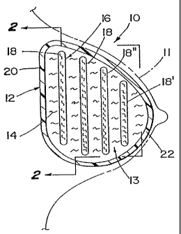
Fig. 2 illustrates a cross sectional front view, taken in the direction of
arrow 2-2
in Fig. 1, of a breast implant with baffles in accordance with the present
invention;
Fig. 3 illustrates a cross sectional side view of a breast implant similar to
Fig. 1 with the baffles tethered to the implant envelope;
Fig. 4 illustrates a cross sectional side view of a breast implant with
baffles in
accordance with the present invention; and
Fig. 5 illustrates a cross sectional front view of a multiple chamber breast
implant with baffles in accordance with the present invention.
DETAILED DESCRIPTION OF THE PREFERRED EMBODIMENTS
With references to the various figures, and initially to Figure 1, there is
shown
a breast implant 10 in accordance with one embodiment of the present invention
implanted in a breast as shown generally by phantom lines 11. The breast
implant 10
includes a conventional envelope 12 preferably constructed of a biocompatible
material,
such as a silicone elastomer. Such an envelope 12 typically has a wall of
sufficient
thickness to provide structural integrity to retain fluids while achieving the
desired
flexibility and malleability of the implant 10. Examples of suitable envelope
materials
are BiocellTM and other materials by McGhan Medical Co.
The envelope 12 defines an interior volume 13 containing a fluid material 14
and
fluid dampening material 16 in conlact with the fluid. The fluid material 14
and
dampening material 16, like the envelope 12, are preferably biocompatible.
Examples
of some suitable fluid materials 14 include saline, silicone gel, and organic
oils such as
peanut or soybean oil. The dampening material 16 may be of a variety of
materials and
configurations, as will be more fully discussed below, which will
appropriately
attenuate the propagation of a fluid wave through interior volume 13 in
response to an
applied force.
CA 02239030 1998-05-29
WO 97/19654 PCT/US95/16380
-4-
The specific fluid material 14 and dampening material 16 are chosen such
that the viscosity and density of the fluid coact with the dampening material
to
provide the interior volume 13 with the simulated static and dynamic
characteristics of natural breast tissue. Consequently, a breast reconstructed
or
enhanced with the implant 10 will feel Iike a natural breast and will
approximate
the movement and feel of a natural breast.
The dampening material 16 may, in one embodiment, be layers of
relatively planar sheets or baffles 18. The baffles 18 may be of the same
material
of which the envelope 12 is made or some other biocompatible material. The
baffles 18 can be oriented parallel to the posterior wall 20 of envelope 12 or
at
any other angle within the envelope depending upon the desired shape, rigidity
and malleability of the implant. Any number of baffles can be incorporated
into
the envelope interior 13 from as few as one to as many as would substantially
fill
the entire volume of the envelope.
With reference to Figs. I and 2, the baffles 18 are shown in a sequentially
enlarging progression from the anterior wall 22 to posterior wall 20 of the
envelope 12 thus generally conforming to the interior contours of envelope.
For
example, baffle 18', near the anterior wall 22 of envelope 12, has a generally
circular shape with a diameter less than baffle 18" placed closer to the
posterior
wall 20 of the envelope. In this manner the baffles 18 provide significant
dampening of a fluid wave propagating through the implant, especially from
posterior to anterior walls 20, 22 or vice versa. Furthermore, the baffles 18
may
be used to provide enhanced dampening and a degree of structural support by
being mechanically fixed to the interior walls of envelope 12 such as through
the
use of tethers 23, as shown in Fig. ~. Selection of ceitain materials and
material
thicknesses for the baffles 18 may also provide a degree of structural support
to
the implant 10.
CA 02239030 1998-05-29
WO 97/19654 PCT/US95/16380
-5-
The baffles 18 may be constructed of a fluid impervious material or a
fibrous or porous material which impedes but does not completely prevent flow
of the fluid material therethrough. One example of a fibrous material is
polyethylene fiber.
With reference to Fig. 4, another type of baffling within a fluid-filled
envelope 12 is illustrated which uses generally spherically shaped baffles 24
which, similar to the sheet baffles 18, can be made of biocompatible
radiolucent
fibrous material which becomes saturated by the fluid material 14 and dampens
dynamic wave front motion of the fluid material 14 within the envelope 12 by
providing physical obstruction to propagation of such waves. Selection of
certain
materials for the baffles 24 within the envelope 12 may also provide
structural
support to the envelope to assist in maintaining the desired shape of the
implant
10. The generaily spherical baffles 24 may freely float within the volume 13
or
one or more of the baffles 24 may be mechanically connected to the interior
walls
of envelope 12 and/or connected to one another, see, for example, baffles 24'
and
24". The spherical baffles 24 act to provide fluid dampening in many
directions
through the implant 10.
The baffles 24 may substantially fill the interior 13 of the envelope 12 so
that the contours of the baffles act to maintain the shape of the implant. The
baffles 24 may also be constructed as one continuous baffle having a shape
matching the desired shape of the envelope 12.
Fig. 5 illustrates a multi-chamber breast implant 26 employing an alternate
fluid dampening system. The internal volume 28 of multi-chamber envelope 30
is subdivided by intemal walls 32 into, for example, four separate chambers a,
b, c, d. The chamber walls 32 can be made of the same material as envelope 12
and can be molded as a single uniform piece with envelope 12. As shown in
chamber a, layered baffles 34 can be made in quarter sections, or sections
which
otherwise conform to the interior of the chamber a, to dampen the fluid
material
CA 02239030 1998-05-29
WO 97/19654 PCT/US95/16380
-6-
14 contained in the chamber in a manner similar to that described with
reference
to Fig. 1. Baffles 34 may or may not be mechanically attached to one another
or to the chamber walls 32 and/or interior walls of envelope 30.
In chamber b there are shown sheet shape baffles 36 oriented within the
chamber perpendicular to the illustrated cross-section of the envelope 30 to
provide a different direction of fluid dampening and structural support than
that
achieved by the baffles 34 in chamber a. In fact, the baffles may be oriented
in
any direction within the chambers to achieve optimum fluid dampening and
structural support. As illustrated in chamber c, generally spherical baffles
38 can
also be included in one or more of the multiple chambers of the envelope to
provide dampening and structural support of the fluid contained therein in a
manner similar to that described with reference to Fig. 4. Further, different
fluid
materials, for example having differing viscosities or densities, may be used
in
separate chambers to attribute different fluid characteristics to the
'different
chambers.
Although the invention has been shown and described with respect to
certain preferred embodiments, it is obvious that equivalent alterations and
modifications will occur to others slcilled in the art upon the reading and
understanding of this specification. The present invention includes all such
equivalent alterations and modifications, and is limited only by the scope of
the
following claims.