Note: Descriptions are shown in the official language in which they were submitted.
CA 02239642 1998-06-OS
2
ANTENNA FOR RADIATINGCABLE TO
VEHICLE COMMUNICATION SYSTEMS
FIELD OF THE INVENTION
The present invention relates generally to communication systems employing a
radiating cable antenna for communicating with a mobile vehicular antenna.
More
particularly, the present invention relates to an improved vehicular antenna
adapted to
communicate with a stationary radiating cable antenna.
BACKGROUND OF THE INVENTION
A variety of techniques and apparatus have been used to satisfy the
requirements of
vehicle communication systems. For example, in a vehicle communications system
including a stationary antenna communicating with a plurality of mobile
antennas, one such
i0 technique is to employ a radiating cable antenna as the stationary part of
the system and
dipole antennas as the mobile part of the system. Generally, radiating cable
antennas
consist of "leaky" coaxial cables having inner and outer conductors separated
by a
dielectric material, in which the outer conductor is provided with either a
continuous slot
or a row of apertures extending lengthwise along the cable. In cables
including a row of
apertures, many apertures are typically provided per wavelength in order to
physically
approximate a continuous slot. In either case, the slot or apertures serve to
couple
electromagnetic signals radiating within the cable to fields radiating outside
of the cable,
such that the cable may be used as a distributed antenna for transmitting or
receiving
electromagnetic energy.
The communications coverage area supported by a radiating cable is dependent
on the length of the cable, the attenuation of the radiated signal along the
length of the
cable and the transfer efficiency (or conversely, "coupling loss") between the
radiating
cable and the receiving antenna. Generally, in a vehicle communication system,
the
length of the radiating cable is relatively long in order to support a
correspondingly large
coverage area. Attenuation of the signal will increase in proportion to the
length of the
cable. Typically, to ensure adequate signal strength along the entire length
of the cable,
the signal is amplified by a series amplifiers positioned along the length of
the cable.
Because these amplifiers are very expensive, reducing the number of required
amplifiers
would significantly benefit the design and cost of a radiating-cable to
vehicle
C: 73172(1KGKO11.DOC)
CA 02239642 1998-06-OS
3
communication system. This may be accomplished by increasing the transfer
efficiency
(i.e. reducing the coupling loss) between the radiating cable and the
receiving antenna
without unduly increasing the cable attenuation.
Another design consideration which would significantly benefit radiating-cable
to
vehicle communication systems is to improve the consistency of the received
signal
level. Where dipole antennas are used as the mobile part of the system, it has
been
determined that the signal received by the dipole can vary approximately 7 to
9 dB with
small vehicle movements. Such large variations in the received signal level in
response
to small vehicle movements necessitates the use of a receiver having a large
dynamic
range and fast time response and contributes to the degradation of the
information being
transmitted.
In view of the above, there is a need for a vehicle communications system
which
increases the transfer efficiency between a stationary radiating cable antenna
and a mobile
receiving antenna without unduly increasing the cable attenuation, thereby
reducing the
required number of amplifiers in the system. Moreover, the system should
support a
received signal level which does not significantly vary in response to small
vehicle
movements. The present invention is directed to addressing each of the
aforementioned
needs.
SUMMARY OF THE INVENTION
~In accordance with one aspect of the present invention, there is provided a
slotted
array antenna for communicating with a stationary radiating cable antenna in a
vehicle
communications system. The radiating cable antenna is adapted to produce a
radiated
field having a first characteristic phase front in response to excitation of
the radiating
cable antenna. The slotted array antenna is operable in a transmit mode or
receive mode.
The slotted array antenna comprises an inner conductor, a dielectric material
surrounding the inner conductor and an outer conductor having a first
plurality of
apertures for passing of electromagnetic radiation therethrough. The apertures
are
positioned in a predetermined relationship along a length of the slotted array
antenna so
as to produce a radiated field having a second phase front determined by the
positions of
said apertures when operated in transmit mode. The slotted array antenna
couples to a
radiated field along the second phase front when operated in receive mode. In
a preferred
C: 73172( I KGKO l LDOC)
CA 02239642 1998-06-OS
embodiment of the present invention, the second phase front is substantially
parallel to
the first phase front.
In accordance with another aspect of the present invention, there is provided
a
communications system comprising a stationary radiating cable antenna and a
mobile
slotted array antenna communicating within a prescribed area. The radiating
cable
antenna includes an outer conductor with a first plurality of apertures for
passing of
electromagnetic radiation therethrough. The apertures are positioned in a
predetermined
relationship along a length of the radiating cable antenna so as to produce a
radiated field
having a first characteristic phase front in response to excitation of the
radiating cable
l0 antenna. The slotted array antenna is substantially parallel to the
radiating cable antenna
and includes an outer conductor with a second plurality of apertures for
passing of
electromagnetic radiation therethrough. The apertures are positioned in a
predetermined
relationship along a length of the slotted array antenna so as to produce a
radiated field
having a second characteristic phase front in response to excitation of the
slotted antenna.
In a preferred embodiment of the present invention, the second phase front is
substantially parallel to the first phase front.
BRIEF DESCRIPTION OF THE DRAWINGS
The foregoing and other advantages of the invention will become apparent upon
reading the following detailed description and upon reference to the drawings
in which:
FIG. 1 is a perspective view of a radiating cable-to-vehicle communications
system according to one embodiment of the present invention;
FIG. 2a is a side elevation view of a slotted array antenna which may be
utilized
in a radiating cable-to-vehicle communications system according to one
embodiment of
the present invention;
FIG. 2b is a cross-sectional view of the slotted array antenna depicted in
FIG. 2a;
FIG. 3 is a top view of a radiating cable-to-vehicle communications system
illustrating matching phase fronts in transmitting and receiving antennas
according to
principles of the present invention;
FIG. 4 depicts a circuit configuration which may be utilized in a radiating
cable-
to-vehicle communications system according to one embodiment of the present
invention;
C: 73172(1KGKO11.DOC)
CA 02239642 1998-06-OS
FIGS. Sa and Sb are block diagrams of a slotted array antenna operated in a
diversity system according to different embodiments of the present invention;
FIG. 6 is a block diagram of a test set-up used to obtain experimental data
regarding a radiating cable-to-vehicle communication system according to one
embodiment of the present invention; and
FIG. 7 is a plot of experimental data obtained using the test set-up of FIG.
6.
While the invention is susceptible to various modifications and alternative
forms,
specific embodiments have been shown by way of example in the drawings and
will be
described in detail herein. However, it should be understood that the
invention is not
1o intended to be limited to the particular forms disclosed. Rather, the
invention is to cover
all modifications, equivalents, and alternatives falling within the spirit and
scope of the
invention as defined by the appended claims.
C: 73172( I KGKO 1 t.DOC)
CA 02239642 1998-09-23
6
DESCRIPTION OF ILLUSTRATIVE EMBODIMENTS
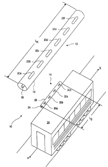
Turning now to the drawings and referring initially to FIG. 1, there is
depicted
a vehicle communication system, generally designated by reference numeral 10,
including a radiating cable antenna 12 and a slotted array antenna 14. The
radiating
cable antenna 12 comprises the stationary part of the system, typically
mounted within
a tunnel or open stretch of highway, railroad or subway. The slotted array
antenna 14
comprises the mobile part of the system, mounted on any of various vehicles
traveling
along the highway, railroad or subway.
It will be appreciated that principles of reciprocity permit either of the two
antennas 12, 14 to be operated in a transmit mode or receive mode. For
example, in
one embodiment of the present invention, the radiating cable antenna 12 is
characterized as a radiating antenna for transmitting electromagnetic energy,
while the
slotted array antenna 14 is characterized as a receiving antenna for receiving
electromagnetic energy. In an alternative embodiment of the present invention,
the
slotted array antenna 14 is characterized as a transmitting antenna and the
radiating
cable antenna 12 is characterized as a receiving antenna. In general, however,
it is
expected that neither antenna will be utilized exclusively as a transmitting
or receiving
antenna, but rather each antenna will be operated in both transmit mode and
receive
mode.
Moreover, because antennas are generally more easily described and
understood in relation to their radiation characteristics, the discussion to
follow may
occasionally describe the respective antennas in terms of their radiated
fields,
radiation pattern, etc. whether they are being used as a transmitting or
receiving
antenna. Nevertheless, it will be appreciated that such descriptions generally
do not
mean that the receiving antenna is producing a radiated field, but rather is
coupling to
fields produced by the transmitting antenna according to a pattern determined
from
principles of reciprocity.
The radiating cable antenna 12 is of the type known in the art, comprised of a
length L of coaxial cable having an inner conductor 16 and an outer conductor
18
separated by a dielectric material (not shown). The outer conductor is
provided with a
row of apertures 20a, 20b, 20c ... 20n (or alternatively, a continuous slot)
extending
lengthwise along the cable. To operate the antenna 12 as a transmitting
antenna, the
CA 02239642 1998-09-23
antenna 12 is excited by applying a radio frequency (RF) signal to the inner
conductor
16, the frequency of which depends on the communications application for which
the
antenna 12 is intended. For example, in an embodiment of the present invention
utilizing the antenna 12 in a train communication system, the antenna 12 is
excited
with an RF signal lying in the relatively narrow frequency rage of 2400-2480
MHz.
After the excitation of the antenna 12, an electromagnetic field is generated
which
propagates in a TEM mode along the length of the cable. The guide wavelength
and
velocity of propagation of the electromagnetic field is dependent on the
excitation of
frequency and the dimensions and materials of the cable.
As the field propagates along the cable, it successively encounters the
various
apertures 20a, 20b, 20c ... 20n positioned along the length of the cable.
Typically,
each aperture is separated from the next successive aperture by a distance
proportional
to the guide wavelength such as, for example, one-half or one-quarter of a
wavelength
between apertures. Alternatively, the apertures may be unequally spaced along
the
length of the cable. In either case, attenuation of the signal along the cable
will
increase in proportion to the length of the cable and in proportion to the
amount of
signal radiated from the apertures 20a ... 20n. Thus, at long lengths of
cable,
amplifiers (not shown) may be required to boost the signal at various points
along the
length of the cable 12 se that the radiated field is maintained at an
acceptable level
throughout the entire length of the cable.
When the RF energy propagating along the cable encounters an aperture, a
portion of the energy "leaks" out into the atmosphere thus defining an
individual
"wave" of RF energy. The remaining portion of the RF energy continues to
propagate
within the cable and encounters the remaining apertures in succession, thus
producing
a plurality of individual waves of RF energy. The individual waves of energy
each
contribute to a radiated field external to the cable which can be detected by
a receiving
antenna. Typically, the magnitude of the waves of energy emanating from the
apertures do not significantly vary from one aperture to the next, but the
phase of the
waves vary in relation to the position of the respective apertures along the
length of
the cable.
For example, with reference to FIG. 3, RF energy S1 propagating within the
radiating cable antenna 12 will first encounter aperture 20a at time to,
causing a
CA 02239642 2000-07-04
8
portion of the RF energy (designated by arrow 22a) to leak out of aperture 20a
into the
atmosphere. Then, at time ti, the RF energy propagating through the radiating
cable
antenna 12 will encounter aperture 20b, causing a portion of the RF energy
(designated by arrow 22b) to leak out of aperture 20b into the atmosphere.
Thereafter,
the RF energy successively encounters remaining apertures 20c ... 20n at times
t2 ... tn,
similarly releasing a portion of the RF energy (designated by arrows 22c ...
20n) to
leak out into the atmosphere. The respective time intervals (to, tl), (t,,
tz), etc.
between encountering each successive aperture is determined by the distance
between
apertures and the velocity of propagation of the RF signal in the cable.
The time intervals between apertures cause the waves of energy emanating
from, each successive aperture to differ in phase from one another. These
phase
differences are depicted graphically in FIG. 3 by the length of successive
arrows 22a
... 22n, with the length of the arrows corresponding to the relative phases of
the
individual waves. For example, the longest arrow 22a represents the wave of
energy
emanating from aperture 20a. The next longest arrow 22b is shorter in length
than
arrow 22a because it represents a phase lag from aperture 20a to 20b, and so
on. The
superposition of the phases of each individual wave thereby defines a phase
front of
the radiated field emerging from the radiating cable antenna 12.
In one embodiment of the present invention, the radiated field produced by the
radiating cable antenna 12 is adapted to be received by a slotted array
antenna 14
mounted on a vehicle such as, for example, a railroad car or automobile, such
that the
axis of the antenna 14 is parallel to the stationary radiating cable antenna
and the
ground. One such configuration is depicted in FIG. l, with the slotted array
antenna
14 mounted on a vehicle 28 comprising a railroad car. Moreover, in a preferred
embodiment, the slotted array antenna 14 is mounted to the vehicle 28 in an
orientation substantially parallel to the axis of the radiating cable antenna
12. In a
preferred embodiment, the vehicle 28 is adapted to move in an axial direction
substantially parallel to the radiating cable antenna 12. For example, with
respect to
FIG. 1, the vehicle 28 may move in either direction along a line drawn from A
to B,
with the line AB being substantially parallel to the radiating cable antenna
12.
The slotted array antenna 14 is comprised of a length 1 of cable having a
cylindrical inner conductor 24 and outer conductor 26 separated by a
dielectric
CA 02239642 2000-07-04
9
material (not shown). The length 1 of the slotted array antenna 14 is sized to
facilitate
mounting on the vehicle 28. The outer conductor 26 includes an array of
longitudinal
slots 30a, 30b ... 30n extending lengthwise along the antenna. Similar to the
radiating
cable antenna 12, the slotted array antenna 14 may be operated as a
transmitting
antenna or receiving antenna. The physical dimensions, number of slots,
distance
between slots, etc. of the slotted array antenna are somewhat arbitrary. For
example,
it is envisioned that the outer conductor 26 may be as small as one-half inch
in
diameter and as large as six inches in diameter, and the number of slots may
be varied
from about three to fifteen in number.
In one embodiment, a reflector (not shown) is positioned behind the slotted
array antenna 14 (e.g., on the mounting surface of vehicle 28). The reflector
serves to
decouple the antenna 14 from the vehicle 28 and other objects behind it so as
to
reduce or eliminate any detrimental effects from the vehicle and/or objects.
When the
antenna 14 is used as a transmitting antenna, the reflector creates a wide
beam in the
plane perpendicular to the array, covering an angular range from the ground to
zenith
on the side of the vehicle 28 facing the receiving antenna 12.
To operate as a transmitting antenna, the slotted array antenna 14 is excited
by
applying an RF signal of a selected frequency (e.g. 2400 to 2480 MHz) to the
inner
conductor 24, thus generating an electromagnetic field propagating along the
length 1
of the antenna 14 between the inner and outer conductors 24, 26. The guide
wavelength and velocity of propagation of the electromagnetic field is
dependent on
the excitation frequency and the dimensions and materials of the antenna 14.
As the
field propagates along the cable, it successively encounters the various slots
30a, 30b,
30c ... 30n positioned on the antenna 14.
Now referring to FIG. 2a, the various slots 30a ... 30n of the slotted array
antenna 14 couple to the RF energy propagating in the cable by means of
respective
metallic protrusions 34a ... 34n, causing the slots to radiate individual
pockets or
waves of RF energy into the atmosphere, similar to the radiating cable
waveguide 12.
As can be seen most clearly in FIG. 2b, the protrusions 34 are positioned
within the
slot 30 such that they are connected to the outer conductor 26 and extend part-
way
toward the inner conductor 24 of the antenna 14. In one embodiment, the
metallic
protrusions 34a ... 34n, are centered on alternating sides of the respective
slots 30a ...
CA 02239642 1998-09-23
30n along the length of the slotted array antenna 14. For example, as shown in
FIG.
2a, protrusions 34a, 34b, 34c and 34d are centered, respectively, on the
upper, lower,
upper and lower side of consecutive slots 30a, 30b, 30c and 30d. However, it
will be
appreciated that the protrusions 34 may be positioned in any of several
alternative
5 orientations relative to the slots 30.
Each of the individual waves of energy (depicted by arrows 32a ... 32n)
emanating from the respective slots 30 is delayed in phase from the waves
emanating
from previous slots. The combination or superposition of waves from each slot
defines a phase front associated with the slotted array antenna 14. The
characteristics
10 of the phase front is determined by the frequency, distance between slots
and the
velocity of propagation of the RF signal in the cable.
When operated as a receiving antenna, the slotted array antenna 14 is designed
to couple to the radiated field generated from the radiating cable antenna 12.
According to principles of the present invention, this coupling may be
achieved with
less coupling loss (e.g. higher transfer efficiency) than other communication
systems
known in the art, by coupling to the radiated field along a matching phase
front. More
specifically, the distance between slots 30 and the velocity and direction of
propagation of the signal in the slotted array antenna 14 are selected so as
to generate
a radiated field with an emerging phase front that progressively matches the
phase
front produced by the radiating cable antenna 12.
For example, in one embodiment of a train communications system utilizing
principles of the present invention, the radiating cable 12 is used as a
transmitting
antenna and the slotted array antenna 14 is used as a receiving antenna. An
excitation
signal of 2400-2480 MHz is applied to the radiating cable 12, causing a
radiated field
to be generated in the direction of the slotted array antenna 14. As described
above,
the phase front of the generated field is dependent on the velocity of
propagation in
the cable 12 and the distance between successive apertures 20a ... 20n. For
purposes
of the present example, it will be assumed that the apertures 20a ... 20n are
each
spaced one-half of a guide wavelength from the next successive aperture.
To couple to the radiated phase field along a matching phase front, the
orientation of the slotted array antenna 14, slot characteristics and
direction and
velocity of propagation within the slotted array antenna 14 are selected to
"match" or
CA 02239642 1998-09-23
11
at least substantially match that of the radiating cable 12. The greater
degree of match
or equalization between antennas corresponds a greater level of transfer
efficiency
(and reduced coupling loss) between antennas. Again, it will be appreciated
that the
degree of coupling loss between the two antennas is substantially independent
of
which antenna is being used as a !ransmitting antenna and which antenna is
being
used as a receiving antenna.
With respect to orientation of the antennas 12, 14, the greatest benefit may
be
achieved where the axis of the stationary and mobile antennas are oriented
parallel to
each other. This optimal antenna orientation may be easily controlled, for
example, in
a railroad or subway communications system in which the stationary radiating
cable
antenna is mounted parallel to the ground, inside or outside of a tunnel, and
the slotted
array antenna 14 is mounted parallel to the ground, on the side of one or more
railroad
or subway cars. However, it will be appreciated that the present invention is
not
limited to railroad or subway applications.
1 S Another design consideration which affects the degree of "match" between
phase fronts is the comparative distance between apertures 20 and slots 30,
respectively, of the radiating cable antenna 12 and slotted array antenna 14.
With
respect to slot distance, however, the comparative distances need not "match"
each
other but generally are at least proportional to each other. For instance, in
the
example heretofore described, with the apertures 20a ... 20n of the radiating
cable 12
spaced one-half of a guide wavelength apart, the slots 30a, 30b, 30c ... 30n
of the
slotted array antenna 14 may be spaced one-half, one-quarter or other suitable
proportion of a guide wavelength from the next successive slot.
FIG. 4 illustrates a simple circuit configuration which may be utilized with a
slotted array antenna according to one embodiment of the present invention. As
shown in FIG. 4, a slotted array antenna 40 is connected via cable 46 to a
load 42.
The load 42 terminates the antenna 40 in a matched impedance. In one
embodiment,
the load 42 comprise a device such as a transmitter or receiver which exhibits
an
impedance matching that of the antenna 40. The susceptance of the slots is
adjusted
so that most of the signal entering the antenna will be radiated and only a
small
portion of it (on the order of -6 to -20 dB) will be absorbed by the load. A
transfer
switch 44 enables an operator to selectively adjust the direction of
propagation of the
CA 02239642 1998-09-23
12
signal within the antenna 40, so that it matches the direction of propagation
in the
corresponding radiating cable antenna (not shown in FIG. 4). More
specifically,
through appropriate adjustment of the transfer switch 44, the direction of
propagation
of the signal within the antenna 40 may be selected or reversed from a
previous
direction.
According to one embodiment of the present invention, the slotted array
antenna may be operated as a diversity antenna. This may be accomplished by
attaching separate transmitters 52, 54 (FIG. Sa) or separate receivers 56, 58
(FIG. Sb)
to each end of a slotted array antenna 50. For example, FIG. Sa depicts a
diversity
system in which the slotted array antenna 50 is being used as a transmitting
antenna,
while FIG. Sb depicts a diversity system in which the slotted array antenna 50
is being
used as a receiving antenna. In FIG. Sa, transmitter 52 excites a signal
propagating
through antenna 50 toward transmitter 54, while transmitter 54 simultaneously
excites
a signal propagating in an opposite direction through antenna 50 toward
transmitter
52. The two oppositely-directed signals each generate a radiated field with a
different
phase front externally to the antenna 50, either of which may be received by a
receiving antenna. In FIG. Sb, the diversity system is designed to receive
signals from
a radiated field by coupling to the radiated field along two different phase
fronts, in
the manner heretofore described.
Typically, in a diversity system, the "isolation" between receivers or
transmitters must be on the order of 20 to 30 dB. In the embodiments depicted
in
FIGS. Sa and Sb, the required isolation is accomplished in part through
attenuation in
the antenna 50 and in part through the phase front mismatch in the two
different
propagating directions. For example, isolation sufficient for a diversity
system may
be achieved by adjusting the susceptance of the slots so that the signal level
reaching
the far end of the antenna (opposite the input end) is 13 to 15 dB less than
the signal
level at the input end of the antenna. The remaining contribution to the
isolation is
furnished by the phase mismatch between the two propagating directions in the
antenna.
Experimental data has demonstrated that the use of the slotted array antenna
14 rather than a conventional dipole antenna in a vehicle communication system
significantly improves both the transfer efficiency and the consistency of the
received
CA 02239642 1998-09-23
13
signal level. FIG. 6 shows a test setup that was used to obtain such
experimental data
in an acoustically insulated test chamber. A 30 foot length of radiating cable
antenna
60 simulating the stationary portion of a vehicle communication system was
excited
with an RF signal at 2400-2480 MHz so as to produce a radiated field in the
direction
of a receiving antenna 62. In separate trials, a vertical dipole antenna and a
slotted
array antenna were used as test receiving antennas, positioned about 24 inches
away
from the axis of the radiating cable antenna 60. T'he respective receiving
antennas 62
were advanced in two-inch increments over a 17-foot distance parallel to the
axis of
the radiating cable antenna 60.
The slotted array antenna used in the test set-up consisted of 10 axial slots
machined in a 1 5/8 inch diameter rigid coaxial outer conductor, with a
reflector
positioned behind the antenna as heretofore described. The array element
(slot)
spacing, slot characteristics and the velocity of propagation were analyzed
and chosen
so that the phase slope of the field generated by the slotted array antenna
would match
the phase slope of the field generated by the radiating antenna 60.
FIG. 7 illustrates the received power versus axial location for the vertical
dipole antenna (designated by reference numeral 75) and the slotted array
antenna
(designated by reference numeral 70). As can be observed in FIG. 7, the
average
signal level 70 received by the slotted array antenna is about 12-15 dB higher
than the
average signal level 75 received by the vertical dipole antenna. The
difference
between the minimum signal level received by the slotted array antenna versus
that
received by the dipole is about 17-19 dB. This would suggest that, in a
vehicle
communications system utilizing a radiating cable antenna and a slotted array
antenna,
the cable length between amplifiers could be increased by about 10-12 dB worth
of
attenuation or about 400 feet (about 30 to 50 percent). This would reduce the
number
of amplifiers needed in the communication system by about 30 to 50 percent.
FIG. 7 also demonstrates a significant improvement in the "smoothness" of the
received signal level. The signal 75 received by the dipole varies 7 to 9 dB
from point
to consecutive point, which are only two inches apart. Conversely, the signal
received
by the slotted array antenna 14 varies only 1 to 2 dB from point to
consecutive point.
This suggests that in a vehicle communications system utilizing a radiating
cable
antenna and a slotted array antenna, the received signal will remain
relatively stable in
CA 02239642 1998-09-23
14
response to small vehicle movements. Accordingly, there will be less
distortion of the
information being transmitted, and there will be less demand for receivers
having a
large dynamic range and fast time response.
While the present invention has been described with reference to one or more
particular embodiments, those skilled in the art will recognize that many
changes may
be made thereto without departing from the spirit and scope of the present
invention.
Each of these embodiments and obvious variations thereof is contemplated as
falling
within the spirit and scope of the claimed invention, which is set forth in
the following
claims.