Note: Descriptions are shown in the official language in which they were submitted.
CA 02240577 1998-06-25 9 ~ ~ 1 9 8 5 9
~'~ ~ ~ ~~C Z~g~
DISPOSABLE ABSORBENT ARTICLE HAVING A REGISTERED GRAPHIC AND
PROCESS FOR MAKING
Qackaround of the Invention
The present invention relates to disposable absorbent articles, and more
particularly to
disposable absorbent articles having registered graphics, and processes for
making the
same.
Various products are fabricated in a continuous production line by the
sequential addition
of components to previously supplied components. This is particularly
advantageous
when one or more of the components can be supplied in the form of a single
continuous
layer. For example, in the formation of disposable absorbent articles, such as
training
pants, diapers, incontinence articles, feminine care products, or the like, a
layer is
normally supplied at a point in the fabrication line in the form of a
continuous roll, and
absorbent pads, waist elastic bands, leg elastic bands, stretchable side
panels, and/or
other elements or components can be supplied at different points in the
fabrication line as
discrete objects.
Various methods and apparatus are available for bringing the components of a
single
product together so that the components in the composite product are in a
desired relation
with respect to each other. In bringing these components properly together,
various
known methods and apparatus are used to note the position of a particular
component,
and then to adjust the position of subsequent components in order to properly
position
them.
A problem encountered with these types of methods and apparatus is that they
do not
adequately compensate for the stretching of a continuously moving layer.
During
manufacturing processes of this type, a continuously moving layer is subjected
to various
tensions caused by it being driven or pulled through the process for handling.
This
1
.. ~....~r ~uee~r
CA 02240577 1998-06-25
i ~ ! ~ n n
~' w 5
~y'-~ °~ ' -''' ~, ~ ~5 ~rG
.~ . ~ ~.. _ ..,1 ~9~
tension causes the continuously moving layer to stretch, or to relax, thereby
resulting in
some components being undesirably positioned or, once positioned, shifted out
of
position. Since it is virtually impossible to maintain a constant tension on
the continuously
moving layer, the degree of stretching varies throughout the process.
Consequently, even
though an earlier positioned component may initially be within an acceptable
position
range, the stretching of the continuously moving layer may result in the
component being
outside of the acceptable position range in the final composite product.
Another problem with current methods and apparatus is that they do not provide
an
adequate means for registering two continuously moving layers, and
particularly when one
of the layers has a pre-printed or pre-positioned component or the like that
is to be
registered with a pre-printed or pre-positioned component or the like on the
other of the
layers during the manufacture of a plurality of products having a desired
registration of
components.
Summary of the Invention
In response to the discussed difficulties and problems encountered in the
prior art, a
disposable absorbent article having a registered graphic and a process
therefor has been
discovered.
In one form of the present invention there is provided a process for
controllably registering
a plurality of components of a continuously moving first layer with a
plurality of reference
marks on a continuously moving second layer. The process includes providing a
continuously moving first layer having a plurality of components thereon,
providing a
continuously moving second layer having a plurality of reference marks
thereon, joining
together the continuously moving first and second layers so that each
reference mark is
associated with a respective component, sensing the position of each reference
mark
relative to its associated component, generating a signal when one of the
reference marks
is out of position relative to its component, processing the signal, and
registering a
subsequent reference mark with a respective subsequent component.
2
- CA 02240577 1998-06-25
°v~/19859
~L. ~,~ ~ ~ ~ ~ ~ C 9I
~ 19
Brief Description of the Drawings
The above-mentioned and other features of the present invention and the manner
of
attaining them will become more apparent, and the invention itself will be
better
understood by reference to the following description of the invention, taken
in conjunction
with the accompanying drawings wherein:
Fig. 1 illustrates a front view of one article having a registered graphic
thereon;
Fig. 2 illustrates a front view of another article having a registered graphic
thereon;
Fig. 2A representatively illustrates the article of Fig. 2 in a partially
disassembled,
stretched flat state;
Fig. 3 illustrates a continuously, moving layer having a plurality of separate
and distinct
graphics thereon;
Fig. 4 illustrates a continuously moving composite layer having a plurality of
separate and
distinct graphics thereon;
Fig. 5 schematically illustrates an apparatus and process for the manufacture
of an article
having a registered graphic thereon;
Fig. 6 illustrates a schematic block diagram of the flow of data utilized in
conjunction with
the apparatus and process in Fig. 5;
Fig. 7 illustrates a block diagram of the electronic gear box in Fig. 6; and
Fig. 8 graphically illustrates a placement control utilized in conjunction
with the apparatus
and process in Fig. 5.
3
-. ..~~.,., ...., ~.s ~
CA 02240577 1998-06-25
~~";i~~' ~r~ j~~~~
r~~ za, ' n n
,:
.:
1
Detailed Description
The following detailed description will be made in the context of registering
and controlling
the registration of one continuously moving layer with respect to a second
continuously
moving layer in the manufacture of disposable absorbent articles, and
specifically a child's
training pant. Examples of other disposable absorbent articles include, but
are not limited
to, diapers, feminine care products, incontinence products, or the like. The
present
invention also contemplates other products or devices unrelated to disposable
absorbent
articles. For the purposes of this description, the term "product" can refer,
but is not
limited, to any article, device, laminate, composite, or the like. The term
"component" can
refer, but is not limited, to designated selected regions, such as edges,
corners, sides or
the like; structural members, such as elastic strips, absorbent pads,
stretchable layers or
panels, layers of material, or the like; or a graphic. The term "graphic" can
refer, but is not
limited, to any design, pattern, or the like.
A child's disposable training pant can have multiple appearance-related and/or
functional
components registered within selected machine-direction (MD) and/or cross-
direction
(CD) ranges. The term "machine-direction" refers to the primary direction of
movement of
continuously moving layers in the manufacturing process, and the term "cross-
direction"
refers to a direction transverse to the machine-direction. The described
example herein is
that of registering a graphic within a designated area of the product.
Thus, the present invention can provide a child's disposable training pant
having one or
more appearance-related or functional components registered with other
components.
Examples relating to components that are appearance-related include, but are
not limited
to, the registration of graphics; highlighting or emphasizing leg and waist
openings in
order to make product shaping more evident or visible to the user;
highlighting or
emphasizing areas of the product to simulate functional components such as
elastic leg
bands, elastic waistbands, simulated "fly openings" for boys, ruffles for
girls; highlighting
areas of the product to change the appearance of the size of the product;
registering
wetness indicators, temperature indicators, and the like in the product;
registering a back
label, or a front label, in the product; and registering written instructions
at a desired
location in the product.
4
;., -.. : .,...,. ~.,, ".p..~,
CA 02240577 2002-03-15
Examples of functional components include, but are not limited to, waist
elastics, leg
elastics, areas of breathability, fluid repellent areas, fluid wettable areas,
adhesives or
coatings, encapsulated inks, chemically-sensitive materials, environmentally-
sensitive
materials, heat-sensitive materials, moisture-sensitive materials, perfumes,
odor control
agents, inks, fasteners, fluid storage areas, textured or embossed areas, or
the like.
The training pant described herein by way of example, comprises an absorbent
pad
positioned between a liquid impermeable outer cover and a liquid permeable
liner. The
training pant further includes elastic side panels which are joined to the
outer cover in
order to provide elasticity thereto. The liquid impermeable outer cover can
comprise two
layers of material suitably joined together, in which the innermost layer can
be a liquid
impermeable layer and the outermost layer can be a nonwoven layer having cloth-
like
texture. The innermost liquid impermeable layer has a graphic printed in
registration
thereon. The registered graphic generally includes a visually pleasing design
or pattern
and is controllably registered at a designated area in the product. One
registered graphic
includes a graphic positioned on the front center of the product. This graphic
is preferably
circular and is about 76 millimeters in dimension, and can range in size from
about 25
millimeters to about 130 millimeters. The center of the graphic is about 83
millimeters
from the front edge of the waist opening. The graphic may include simulated
elastic leg
bands, a simulated elastic waistband, a simulated '°fly opening" for
boys, simulated ruffles
for girls, or the like.
A more detailed description of the construction and design of the above-
described training
pant can be found in U.S. Patent No. 4,940,464 issued July 10, 1990.
Described herein is a distinctive process and apparatus for registering a
plurality of
distinct and separate components on a continuously moving first layer of
material with a
respective plurality of distinct and separate components on a continuously
moving second
layer of material. The second layer of material has the components suitably
represented
by respective reference marks, both provided thereon at a uniform repeat
length shorter
than a machine product repeat length. The distance between two successive
reference
marks is determined and then used to calculate a desired speed for the current
process
conditions. The second layer of material is then controllably stretched or
relaxed so that'
the distance between two successive reference marks substantially equals the
selected
5
- CA 02240577 1998-06-25
-,'~ >i . , ~:, -, ..
r~.~.~c r~ nr ~
.. . 'c~ ~s ~ r1 e~ ~'~ ". '' ~'. ~ -vf
_ ... , _ 4.
distance, which in this case is one machine product repeat length; this is
termed the
"repeat loop". The second layer is then controllably registered to the first
layer of material
so that each reference mark is selectively registered with a respective
component; this is
termed the "placement loop". The amount of stretch or relaxation can be
controllably
adjusted by varying the speed and/or tension of the second layer. The term
"reference
mark" can refer, but is not limited, to structure such as waist or leg
elastics, adhesive
beads, corners or edges of structure, transporting mediums such as conveyor
belts, visual
marks, magnetic marks, electrical marks, electromagnetic marks, optical
brighteners
sensitive to ultraviolet radiation, or the like, all of which can be sensed,
detected, or
otherwise identified by an appropriate device. The term "machine product
repeat length"
refers to a selected distance, which in this example is the measured distance
between
successive, like components during manufacture. For example, between
successive
waist bands, absorbent pads, or the like. Or in other words, the machine
product repeat
length is the length of one product during the manufacturing process. Thus,
when a
reference mark is registered with a component of the first layer, then the
component
represented by that reference mark is registered with the component of the
first layer.
With regard to the repeat loop, the second layer has the reference marks
selectively
provided thereon to correspond to a respective plurality of distinct and
separate
components, such as graphics. A first sensor generates a signal in response to
each
reference mark. The distance between each newly generated signal and the most
recently preceding signal is suitably measured in units of a driving
mechanism, so that the
speed of the driving mechanism can be selectively controlled to adjust the
speed and/or
tension of the second layer to controllably stretch or relax the second layer,
such that the
distance between a subsequent newly generated signal and its most recently
preceding
signal is one machine product repeat length. Thus, the repeat loop refers to
repeatedly
duplicating a product length between two successive reference marks by
accurately
measuring their current distance apart and calculating a desired speed
reference for a
main drive control system.
With regard to the placement loop, a desired registration of a reference mark
to a
component is performed by comparing and controlling a related datum value to a
target
set point. A "datum value" refers to a measured distance between a reference
mark and
a machine-generated constant reference signal. A "target set point" refers to
a selected
value within which the datum value is maintained.
6
_ . . . ~ r .,_ ~..~
CA 02240577 1998-06-25 _ ,
-.
~ . 4
There is described herein, by way of example, a distinctive process and
apparatus for
using a preprinted, stretchable second layer of material including a plurality
of distinct and
separate graphics thereon, stretching this second layer to a selected length
by varying the
speed and/or tension thereof, and then applying and registering it to another
layer that
includes preassembled, preapplied components, such as absorbent pads, thereby
providing a manufacturing process for individual disposable absorbent articles
having
graphics registered thereon at designated areas. The process and apparatus can
also be
used to apply, during manufacture, other various functional and appearance-
related
components that have been printed, joined, positioned, or the like, on a layer
at a
specified location so as to be selectively registered in the final product.
The second Payer of material can be a continuous polyethylene film preprinted
with a
plurality of separate and distinct graphics. The printed graphics are arranged
such that
they ultimately will be positioned at the same designated area in each
finished product.
The term "finished" or "final", when used with reference to a product, means
that the
product has been suitably manufactured for its intended purpose.
The second layer is controllably stretched or relaxed, using tension and/or
speed
variations, to appropriately correspond the distance between two successive
reference
marks to the machine product repeat length and to control a related datum
value to a
target setpoint. This is done in order to register the reference marks to
previously
processed and preplaced components, such as, by way of example, absorbent
pads. The
use of the term "stretchable" refers to that property of a material or
composite material
that permits it to recover at least a portion of its original size and shape
after removal of
the force causing the deformation. The stretch of the second layer is
controlled by
increasing or decreasing speed and/or tension using an electronically
controlled, motor
driven roll. Once the second layer is stretched to the desired or proper
length, it may, if
desired, be joined to another layer, such as a nonwoven, spunbond web to
substantially
stabilize the second layer, thereby reducing or eliminating its
stretchability. A system of
sensors used in conjunction with computer hardware and software inspects for
registered
location, repeat patterns, and setpoint error. The data received from these
sensors is
used to control the motor, which adjusts the second layer's speed and/or
tension as
necessary for desired registration. Adjustments to the second layer are made
so that the
preprinted graphics are desirably registered with a respective plurality of
components.
7
CA 02240577 2002-03-15
These features advantageously control a layer moving at high speed in order to
register it
with another layer. In particular, there is provided accurate, real time
information during
the production process, and rapid adjustments to the process to provide the
desired
configuration and registration of the reference marks and their associated
components in
the final product.
The use of the term "layer" can refer. but is not limited, to any type of
substrate, such as a
woven web, nonwoven web, films, laminates, composites, elastomeric materials,
or the
like. A layer can be liquid and air permeable, permeable to air but
impermeable to liquids,
impermeable both to air and liquid, or the like.
Each of the separate and distinct graphics on the continuously moving layer
has a
reference mark associated therewith. This means that each reference mark is
selectively
positioned with regard to a respective graphic, so that the reference mark can
be sensed
and appropriately registered in the product, thereby properly registering each
graphic in its
product. Earlier, a reference mark was described in terms of specific
examples, and in
the following description the reference mark is selected as an optical
brightener. A
reference mark, whether an optical brightener or other means, can be
configured in any
desired size or shape. The reference mark may comprise a generally rectangular
region
having a machine direction dimension of about 19 millimeters and a cross
direction
dimension of about 37 millimeters. Other dimensions optionally may be
employed. It is to
be understood that the various detecting and sensing means described herein
are to be
appropriately compatible with the type of associated reference mark that is to
be detected
or sensed. The term "associated" refers to the reference mark either being
directly on a
component that it represents, such as a graphic, or being selectively spaced
therefrom.
The optical brightener is provided to be sensitive to ultraviolet radiation.
The optical
brightener is, for example, capable of absorbing ultraviolet radiation and
then fluorescing
to emit light spectra that can be sensed by an appropriate and compatible
detector or
sensor. Ultraviolet radiation is generally understood to include
electromagnetic radiation
having wave lengths ranging from about 20-400 manometers. Suitable optical
brighteners
TM TM
include, for example, UVITEX OB manufactured by Ciba-Geigy, and LEUCOPURE EGM
manufactured by Sandoz Chemicals Corporation
8
CA 02240577 2002-03-15
Where the reference mark comprises ultraviolet sensitive optical brighteners,
a suitable
TM
detector or sensor is a UV activated detector, such as a SICK detector model
LUT 2-6
available from SICK OPTIK ELEKTRONIK, INC., a business having offices in St.
Paul,
Minnesota.
Other suitable reference marks, as well as sensors, computer devices, motors,
and the
like are described in U.S. Patent No. 5,235,515; U.S. Patent No. 5,359,525;
and U.S.
Patent No. 4,837,715.
The described process and apparatus utilize several devices, and
representative devices
include encoders, signal counters, and sensors. An encoder generates a pulse
train,
which is a selected number of pulses per revolution of the encoder shaft, for
subsequent
counting and control. A signal counter receives a generated pulse train from
an encoder,
and counts the pulses for subsequent query. A sensor senses an occurrence or
interruption in a process and generates a signal in response thereto.
Referring now to Fig. 1, there is illustrated a child's disposable training
pant 10 generally
comprising a front panel 12, a back panel 14, a crotch panel 16
interconnecting front and
back panels 12, 14, and a pair of elastic side panels 18. Each elastic side
panel 18 is
formed from two separate elastic portions (Fig. 2A) and are suitably joined
together, such
as by ultrasonic bonding, to form a side seam 20. Upon the construction of
side seams
20, a waist opening 22 and leg openings 24 are formed. The side seams 20 may
be
constructed to be manuaNy tearable in order to allow training pant 10 to be
disassembled
manually by the caregiver, so that it can be easily removed from the child
after a bowel
movement. The elastic side panels 18 (Fig. 1 ) and side seams 20 can be
provided in any
suitable manner. One specific manner of supplying elastic side panels '18 is
described in
U.S. Patent No. 5,224,405 and U.S. Patent 5,104,116.
The provision of side seams 20 can be accomplished in the manner
described in U.S. Patent No. 5,046,272.
Training pant 10 further comprises a front waist elastic 26 suitably joined to
front panel 12,
a back waist elastic 28 suitably joined to back panel 14, leg elastics 30
suitably joined to
crotch panel 16, and an absorbent pad 32 (Fig. 4) positioned between a liquid
impermeable outer cover or backsheet 34 (Fig. 1 ) and a liquid permeable liner
or topsheet
9
CA 02240577 2002-03-15
36. The basic construction of a training pant is well known in the art, and
one particular
construction is that described in U S. Patent No 4.940,464, issued July 10,
1990.
U.S. Patent 4,940,464 also
describes various materials of which a training pant can be made, and the
methods of
constructing the training pant.
As illustrated in Fig. 1, a registered graphic 38 is selectively positioned on
front panel 12,
and in this illustration comprises a design of a simulated "fly opening 23",
typical of a boy's
underwear, and a rainbow, sun, clouds, and cars. The registered graphic 38 can
be any
type of desired pattern, artistic feature, written instructions, or the like,
and is desired to be
positioned in the article at a selected location. Naturally, registered
graphic 38 comprising
a simulated fly opening 23 would be totally unacceptable from an aesthetic
and/or
functional viewpoint if it were located at crotch panel 16 or back panel 14.
Referring to Fig. 2, another training pant 40 is illustrated, which can be
typically used for
young girls. In this design, a registered graphic 42 includes simulated waist
ruffles 29,
simulated leg ruffles 31, a rainbow, sun, clouds, wagon and balloon. Again,
any suitable
design can be utilized for a training pant intended for use by young girls, so
as to be
aesthetically and/or functionally pleasing to them and the caregiver.
Registered graphic 38 in Fig. 1 or registered graphic 42 in Fig. 2 can be
controllably
registered as desired, depending upon the size and shape of the graphic and
that portion
of the article upon which the graphic is to be registered. In Fig. 1, graphic
38 is
controllably registered within a designated area 39 which, as viewed in Fig.
1, is bounded
or defined by a front waist edge 116, panel seams 21, and a crotch panel line
17. Panel
seams 21 are the seams at which the respective elastic side panels 18 are
suitably joined
to front panel 12 and back panel 14. Again, a more specific description of the
construction and manufacture of this design of a training pant 10 is contained
in the
aforementioned U.S. Patent 4,940,464. The crotch panel line 17 is, for
purposes of
explanation herein, simply the line or boundary formed at the bottom of crotch
panel 16 as
illustrated in Fig. 1. Thus described, designated area 39 has four defined
boundaries
comprising front waist edge 116, panel seams 21, crotch panel line 17, and
those portions
of leg openings 24 extending between a respective panel seam 21 and crotch
panel line
17. It is not necessary that a designated area 39 be completely defined or
bounded by a
closed line or closed boundary. For example, in Fig. 1, the designated area 39
could be
CA 02240577 1998-06-25
~~~ ~ ~ ~ ~ C 1991,
defined by only front waist edge 116, panel seams 21, which sufficiently
define a
designated area 39 in which a graphic 38 can be controllably registered. In
this case, the
graphic 38 can be controllably registered a selected distance from front waist
edge 116,
and centered between panel seams 2 t .
Another example of the flexibility in choosing a designated area 39 is
illustrated in Fig. 2A,
which illustrates the training pant 40 in Fig. 2 in a partially disassembled,
stretched flat
state. This can be accomplished by taking the finished training pant 40 of
Fig. 2 and
manually tearing seams 20 and then laying the pant 40 flat and stretching it
sufficiently to
remove any gathers or pleating caused by any incorporated elastic members. In
Fig. 2A,
designated area 39 is defined or bounded by front waist edge 116, panel seams
21, back
waist edge 118, and a pair of leg opening edges 25 extending between
respective panel
seams 21. Thus, in Fig. 2A, designated area 39 is generally rectangular in
shape, and
registered graphic 42 is registered within and throughout the surface area of
designated
area 39. Registered graphic 42 comprises several component designs, such as
simulated
leg ruffles 31 and simulated waist ruffles 29. As viewed in Fig. 2A, leg
opening edges 25
are linear or straight lines. However, in Fig. 2, simulated leg ruffles 31
provide a
perceived curvature or shape to training pant 40, which is one of the unique
features
herein.
There is uniquely and advantageously provided a very close tolerance in the
registration
of a desired component, such as graphics 38, 42, within any selected area,
such as a
designated area 39. With reference to Fig. 1, it is apparent that the
simulated fly opening
23 of graphic 38 needs to be registered within front panel 12. It would be
undesirable to
have training pant 10 manufactured by a method and/or apparatus that could not
control
the proper registration of simulated fly opening 23, otherwise the simulated
fly opening 23
could appear at back panel 14 or crotch panel 16. The present invention
provides a highly
controlled registration of a desired component, such as a graphic 38 or 42,
within a
desired designated area, such as designated area 39, within a tolerance of
about plus or
minus 6 millimeters, and within a more particular tolerance between about plus
or minus
3 millimeters.
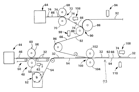
Referring now to Fig. 5, there is schematically shown an apparatus and process
for
assembling in part a plurality of training pants. A supply means 44
continuously supplies
a continuous, tissue-wrapped absorbent 46 to a separating means 48 that
separates the
11
__ ~ . t,..._~.i,
CA 02240577 2002-03-15
continuous, tissue-wrapped absorbent 46 into a plurality of distinct and
separate
absorbent pads 32. The supply means 44 can be any conventional mechanism for
supplying the absorbent 46. Generally, a conventional supply means 44 will
include a
hammermill for forming fluff fibers and, if desired, for providing an
enclosure for mixing
superabsorbent material with the fluff fibers, and then depositing the fluff
and
superabsorbent material on a forming drum having a desired absorbent design.
The
forming drum then deposits the shaped absorbent on a continuously moving
tissue
material, which is thereafter delivered to a folding board for folding the
tissue about the
absorbent. This provides the continuous, tissue-wrapped absorbent 46. The
absorbent
can include any desired mixture or blend of absorbing materials, such as fluff
and
superabsorbent materials. Suitable superabsorbent materials are available from
various
commercial vendors such as Dow Chemical Company, Hoechst-Celanese Corporation
and Allied Colloids, Inc. Typically, a superabsorbent material is capable of
absorbing at
least about 15 times its weight in water, and desirably more than about 25
times its weight
in water. A preferred fluff is that identified with the trade-mark CR1654,
available
from Kimberly-Clark Corporation, Neenah. Wisconsin, and is a bleached, highly
absorbent
sulfate wood pulp containing primarily soft wood fibers.
A conveyor means 50, which can be any conventional conveyor means well known
in the
art, conveys the absorbent 46 to the separating means 48. A supply means 52
provides a
continuously moving first layer of material 54, upon which can be disposed any
desired
component, such as the separate and distinct absorbent pads 32 formed by
separating
means 48. The supply means 52 can be any standard unwind mechanism that
generally
comprises a pair of spindles, a festoon assembly, and a dancer roll for
providing first layer
54 at a desired speed and tension. One example of a standard unwind is a model
MB
820, available from Martin Automatic Corporation of Rockford, Illinois. The
continuously
moving first layer of material 54 can be any desired material suitable for the
particular
product being assembled. In this description of a training pant 10 (Fig. 1 ),
continuously
moving first layer 54 is a liquid permeable material that will subsequently
form or become
liquid permeable topsheet 36 (Fig. 1 ). Topsheet 36 can be made of any
suitable materials
well known in the art, and examples of suitable materials are described in the
aforementioned U.S. patents.
Upon being moved or delivered to separating means 48, the continuous, tissue-
wrapped.'
absorbent 46 is cut into the separate and distinct absorbent pads by a knife
roll 56 and an
12
CA 02240577 2002-03-15
anvil roll 58 comprising separating means 48. The knife roll 56 can have any
desired
r~mber of blades thereon, and in this example has two blades 60 diametrically
disposed
thereon for forming absorbent pads 32. Knife roll 56 is driven by and
mechanically
coupled through gearing to anvil roll 58, which is operatively driven by a
main lineshaft
128 (Fig. 6) in any suitable manner well known in the art. A constant
reference means,
such as a proximity switch 62, is coupled to anvil roil 58 for generating a
reference signal
for each cut absorbent pad 32. For purposes herein, the separating means 48 is
operated
at a substantially constant speed during the manufacturing process so that
each reference
signal generated by proximity switch 62 is considered a machine constant
reference
signal for purposes of comparison to other signals hereafter described. The
machine-
generated constant reference signal from proximity switch 62 is transmitted to
a main
control system for further processing as described hereafter.
The distinct and separate absorbent pads 32 formed by separating means 48 are
positioned upon the continuously moving first layer of material 54 provided by
supply
means 52. It is well known in the art to separate and position individually
cut absorbent
pads onto a continuously moving layer, and any such suitable mechanism can be
utilized
herein.
A supply means 64, which can be a standard unwind similar to that used with
reference to
the supply means 52, provides a continuously moving second layer 66 of
material that will
subsequently be joined to continuously moving first layer 54. The continuously
moving
second layer 66 can be any material suitable for the finished product, and in
this particular
description is a liquid impermeable film that will subsequently form liquid
impermeable
outer cover 34 (Fig. 1 ). One desired suitable liquid impermeable film is a
0.75 mil
polyethylene film commercially available from Edison Plastics Company of South
Plainfield, New ,lersey. Continuously moving second layer 66 is moved toward a
pair of
rolls comprising a drive roll 68 and a support roll 70 that form therebetween
a feed nip 72.
Drive roll 68 can be driven by any suitable motor, such as those described in
the U.S.
patents noted above. A suitable feed nip motor is a HR 2000
brushless AC servo motor available from Reliance Electric Company, of
Cleveland, Ohio.
The material of which second layer 66 is made is desirably stretchable, in
that it can be
stretched, by way of example only, between about 5 to about 15 millimeters.
Other
materials having greater or lesser stretch can be utilized as the material or
materials for
second layer 66.
1:3
CA 02240577 1998-06-25
ai a
i' r s: '.
c-. . ; .7 iw .~ .9.
= .., '~ ~ .. v.i
It is important that the feed nip motor 148 (Fig. 6) and its drive system,
which operates
drive roll 68, is one that is capable of performing two types of speed
variations, as
controlled by the main control system, which will be described in greater
detail hereafter.
One speed variation is to increase a present speed of the rotation to a faster
speed of
rotation, or to decrease a present speed of rotation to a slower speed of
rotation. The
other speed variation is a momentary speed variation comprising an incremental
advance
phase move, which is a momentary speed increase of drive roll 68 to provide a
measured
increased amount of the layer of material, or an incremental retard phase
move, which is
a momentary speed decrease of drive roll 68 to provide a measured decreased
amount of
the layer of material. The term "momentary speed increase" refers to
increasing a first
speed to a higher second speed for a selected period of time, and then causing
or
allowing the speed to return to the first speed, in order to advance the
position of the layer
and the associated graphics upstream of the nip by a measured amount. The term
"momentary speed decrease" refers to decreasing a first speed to a lower
second speed
for a selected period of time, and then causing or allowing the speed to
return to the first
speed, in order to retard the position of the layer and the associated
graphics upstream of
the nip by a measured amount.
As described earlier, the present invention can be utilized to register two
continuously
moving layers together, so that a reference mark and/or product component of
one layer
is registered with a reference mark and/or product component on the second
layer. In this
particular description, a component, such as a registered graphic 38 (Fig. 1 )
on
continuously moving second layer 66 (Fig. 5) is brought in registration with a
component,
such as an absorbent pad 32, on continuously moving first layer 54. By
controllably
registering a registered graphic 38 with an absorbent pad 32, the desired
position of
registered graphic 38 on a front panel 12 (Fig. 1 ) of a training pant 10 can
be
accomplished. An important function of a registered graphic 38 on a front
panel 12 is that
it visually informs the user of the proper orientation of the training pant 10
for donning
purposes, thereby permitting the training pant to properly function, i.e.,
absorb waste,
among other functions. The continuously moving layer 66 has, by way of
example,
preprinted thereon a plurality of separate and distinct graphics 38,
understanding again
that a graphic 38 can be any desired design or pattern, such that the graphics
38 can be
registered with the separate and distinct absorbent pads 32 on continuously
moving layer
54. There is associated with each graphic 38 a preprinted reference mark 74,
which in
14
CA 02240577 1998-06-25 ~ r
<r ,.,,
E~ ~,~ ~~ ~ ~ D E ~ 9
this case is an optical brightener. The graphics 38 and their respective
reference marks
74 can be provided on layer 66 in any suitable manner well known in the art.
With reference to Fig. 3, there is illustrated a portion of continuously
moving layer 66
having a plurality of the graphics 38 and reference marks 74 preprinted or
prepositioned
thereon. Associated with each graphic 38 is a printed waistband 76 with a
printed front
edge 78 and a printed back edge 80. Similarly, each reference mark 74 has a
reference
front edge 82 and a reference back edge 84. Each reference mark 74 will be
used to
properly position an associated graphic 38 with an absorbent pad 32. The
reference
marks 74 are positioned off graphics 38, but could be printed directly on the
graphics 38
so as to be within the design of the graphics. Furthermore, the reference
marks 74 can
be eliminated, and a portion of a graphic 38 can be used as the reference
mark. For
example, a detectable mark or the like could be printed as part of the
waistband 76 and
thereafter used for properly registering the graphic 38. However, for purposes
of
explanation and manufacture, reference marks 74 are provided a selected
distance apart
from respective graphics 38.
In the following description, the continuously moving second layer 66 will be
described, by
way of example, as being joined or laminated to another third layer 92 (Fig.
5) of material
in order to produce a two-layered laminate 93 that ultimately will form the
liquid
impermeable outer cover 34 (Fig. 1 ). The polyethylene film material of which
layer 66 is
made serves as a liquid impermeable barrier, while the third layer of material
joined to
layer 66 will provide cloth-like texture to the outer cover. The cloth-like
layer will be the
outermost layer. There is no requirement, however, for the third layer, and in
some
product designs, the cloth-like layer can be eliminated.
Layer 66 is driven or moved toward a laminator chill roll 86 and an associated
support roll
88, which form therebetween a laminator nip 90. A continuously moving layer 92
is
provided in any suitable manner, and driven in any suitable manner to
laminator chill roll
86. An adhesive applicator 94 applies a desired pattern of a suitable adhesive
to the
continuously moving layer 92. In this particular embodiment, layer 92 is a
nonwoven web,
such as a spunbond polypropylene web having a basis weight of about 20 grams
per
square meter (gsm). The adhesive applicator 94 can be any suitable applicator
well
known in the art that can provide or apply the desired pattern of adhesive.
The adhesive
used can be any suitable adhesive that is compatible to layers 66 and 92, in
order to
- CA 02240577 1998-06-25
~.~=,rs n ~ y; ~ n ~~ r
a.~.-.~ ~ ..::~ . . ~ ~~ r zg9_
ensure their proper lamination together. Continuously moving layer 92 can be
provided by
a supply means (not shown) similar to supply means 52 and 64.
Laminator chill roll 86 is driven by the lineshaft 128 (Fig. 6) and assists in
moving the
layers in the process. The laminator chill roll 86 also serves to cool the
adhesive applied
by adhesive applicator 94 for processing purposes, thereby preventing
adhesives from
bleeding through the layers 66 or 92.
Once layers 66, 92 are laminated and pass through laminator nip 90, they are
continuously moved to a construction chill roll 96, and have an adhesive
applied to the
outermost surface of layer 66. Construction chill roll 96 is lineshaft driven
by lineshaft
128, similar to chill roll 86. The adhesive applied by adhesive applicator 98
will ultimately
join layers 66, 92 to continuously moving first layer 54. Thus, adhesive
applicator 98 is
selected to apply the appropriate adhesive pattern and amount of adhesive to
ensure the
desired joining of the layers 66, 92, and 54. The construction adhesive
applicator 98, as
well as the adhesive applied thereby, can be any type of applicator suitable
for the desired
adhesive pattern, and appropriate and compatible for the materials to be
joined.
From construction chill roll 96, the laminated layers 66, 92 are then
superimposed over
continuously moving layer 54, and together the layers pass through a product
tacker 100
comprising a drive roll 102 driven by lineshaft 128 (Fig.6) and a rubber-
coated idler roll
104. Tacker 100 compresses the layers together in order to cause the applied
adhesive
to join layers 66, 92 to continuously moving layer 54, thereby forming a
continuously
moving composite laminate 93 as illustrated in Fig. 4.
Continuing to refer to Fig. 5, a first sensing means, such as a sensor 106, is
suitably
positioned between drive roll 68 and laminator chill roll 86 for detecting and
generating a
signal in response to each reference mark 74. Since the reference marks 74 are
ultraviolet-sensitive optical brighteners, a suitable sensor is a SICK
detector model LUT 2-
6 available from SICK OPTIK ELEKTRONIK, Inc., having a business office in St.
Paul,
Minnesota.
Positioned downstream of product tacker 100 are a second and third sensing
means,
such as a sensor 108 and a photoeye 110. The term "downstream" refers to a
left-to-right
direction as viewed in Fig. 5, and is also the machine direction for the
process.
16
. :~s
CA 02240577 1998-06-25
4~~~~~ Q ' / ~. 9 ~ 5 9
~~ $',~;~ '.' ~ ~ ~ C 1991
Parenthetically, although layers 66 and 92 are illustrated as moving in a
downwardly
direction, the primary direction in which they are moving or will eventually
move is in a left-
to-right direction, and is also thus termed the downstream direction. Sensor
108 can be
the same type of ultraviolet detector as sensor 106. The photoeye 110 is
desirably a
Banner RSBF scanner block, RPBT wiring base, IR 2.53S fiber-optic pair device,
available
from Banner Engineering, Corp. of Minneapolis, MN. Photoeye 110 is designed to
optically detect a product component, such as absorbent pad 32, and to
generate an
electrical signal in response thereto. In this particular description, both
sensors 106 and
108 are designed to detect and generate a signal in response to a reference
mark 74, and
photoeye 110 is designed to detect and generate a signal in response to an
absorbent
pad 32. If desired, photoeye 110 can sense other components, such as waist
elastics, leg
elastics, fastening tapes utilized in diapers, or the like. A reference mark
also can be
associated with each absorbent pad 32 in the same manner that a reference mark
74 is
associated with a graphic 38; and in that case, the pad photoeye 110 can be
replaced
with a sensor similar to sensors 106, 108. Similarly, sensors 106, 108 can be
replaced
with other sensors, similar to photoeye 110, in order to optically detect a
product
component or other structure in order to generate an appropriate signal.
With reference to Fig. 4 and Fig. 5, there is illustrated a continuously
moving composite
laminate 93 comprising layers 66, 92, and 54 after they have been joined
together by
product tacker 100. Each printed waistband 76 will ultimately be cut along a
respective
cut line 120 in order to form individual products. In Fig. 4, once cut lines
120 have been
separated, a front waist edge 116 and a back waist edge 118 are formed for
each
assembled product. One of the important features in Fig. 4 is the relative
placement of a
graphic 38 with respect to each product that will eventually be formed. Each
graphic 38 is
located in the front panel 12 (Fig. 1 ) and is located in the same position
relative to an
absorbent pad front edge 112 (Fig. 4). Naturally, other marks or product
components can
be in registration with other different reference marks or product components.
For
example, a simulated waist ruffle 29 (Fig. 2) can be registered relative to a
waist opening,
or leg elastics, such as leg elastics 30 (Fig. 1 ), can be desirably
registered in relation to an
absorbent pad, such as absorbent pad 32 (Fig. 4).
Referring to Fig. 6, there is schematically illustrated a main control system
with the
mechanical side 122. The main control system comprises a main registration
control
system 124 that receives various generated signals, processes them in
accordance with
17
.. . _ , _,.,~,.. ....,.,e.",
CA 02240577 1998-06-25 ~ ~ v j 1 9 8 5 9
~~~~~ ~ ~' D E C 1991,
programmed instructions, and generates output signals to a main drive control
system
126. The main drive control system 126 receives the signals from the main
registration
control system 124, and in response thereto operatively adjusts drive roll 68
(Fig. 5).
Mechanical side 122 comprises a lineshaft 128 that directly drives selected
mechanisms
or, through a system of gears and other coupling devices, both electrical and
mechanical,
indirectly drives other mechanisms. Lineshaft 128 is driven at a constant
speed, by any
suitable means known in the art. Thus, those mechanisms driven by lineshaft
128 are
also driven at a constant speed, which may or may not be the same speed as
that of
lineshaft 128. Specifically, a feed nip gearing encoder 130 and a fineshaft
registration
encoder 132 are operatively coupled to lineshaft 128. Examples of encoders
include an
H25D-SS-2500-ABZC-8830-LED-SM18 (which can be used as encoder 130), available
from BEI Motor System, Co. of Carlsbad, California, and a 63-P-MEF-1000-T-0-00
(which
can be encoder 132) available from Dynapar Corp. of Gurnee, Illinois. Feed nip
gearing
encoder 130 is operatively coupled to lineshaft 128 to rotate at a constant
speed, and
such that four revolutions of encoder 130 represents one machine-generated
product
length, i.e., a machine product repeat length.
The main registration control system 124 comprises hardware and/or
preprogrammed
software instructions, and can be represented, with reference to Fig. 6, as
comprising an
input acquisition system 134, a gear ratio control 136, a relative position
138, an
automatic set point generation 140, a difference block 142, and a placement
control 144.
The main registration control system 124 includes a computer, which can
comprise, for
example, a VME-based microprocessor, such as a SYS68K/CPU-40B/4-01 available
from
Force Computers, Inc. of Campbell, California.
As illustrated in Fig. 5 and Fig. 6, input acquisition system 134 receives the
following six
generated signals: (i) a signal from a motor encoder 146 operatively coupled
to the feed
nip motor 148, (ii) a signal from sensor 106 (Fig. 5), (iii) a signal from
proximity switch 62,
(iv) a signal from lineshaft registration encoder 132, (v) a signal from
sensor 108, and (vi)
a signal from photoeye 110. Input acquisition system 134 receives and counts
the pulses
generated by motor encoder 146 and lineshaft registration encoder 132, and
receives
signals from sensors 106, 108, proximity switch 62, and photoeye 110.
Referencing the
accumulated counts of encoder 146 and the accumulated counts of encoder 132,
input
18
.-
CA 02240577 1998-06-25
-.,r .~
"'.~'~' :' ;
acquisition system 134 performs preprogrammed instructions that are specific
to the
respective received signals, and stores the results of the instructions.
The input acquisition system 134 performs the following functions for the gear
ratio control
136. A signal counter in input acquisition system 134 counts the pulses from
motor
encoder 146, and receives signals from sensor 106 in response to each
reference mark
74 (Fig. 5). The input acquisition system 134 then measures the counted pulses
representing a distance between every two successive reference marks 74, and
performs
a running average of those measured counts. The term "running average" refers
to
averaging the same number of data; for example, for each newly received datum
input,
the latest, i.e. the oldest, datum is removed from the averaging calculation.
The
averaging of the counts between two successive reference marks 74 creates an
average
measurement upon which the next gear ratio value will be derived by gear ratio
control
136, as opposed to basing a control decision on the measurement from just one
pair of
reference marks 74. This averaging "smooths out" the measurements, and is
necessitated due to the variability of the apparatus and process. The number
of
measurements to average is controllable, and is set or determined by providing
an
appropriate instruction via manual input in any suitable manner well known in
the art. In
conjunction with performing a running average of the measured counts, the
input
acquisition system 134 performs a filtering function, which is preprogrammed,
to filter out
signal anomalies. Examples of such signal anomalies include a dirty photoeye,
missing or
extra reference marks 74, movement or weaving of the layers, measuring the
counts
outside a preprogrammed range for averaging purposes, known inaccurate data
due to
registration control events, or the like.
The input acquisition system 134 performs the following functions for the
relative position
138. The input acquisition system 134 counts the pulses received from
lineshaft
registration encoder 132, and receives signals generated by sensor 106 and
proximity
switch 62. Input acquisition system 134 then determines and records the
current
accumulated number of pulses upon receiving a signal from sensor 106, and
determines
and records the current accumulated number of pulses upon receiving a signal
from
proximity switch 62.
The input acquisition system 134 performs the following functions for the
automatic set
point generation 140. Input acquisition system 134 counts the pulses received
from
19
CA 02240577 1998-06-25
RII:A
~~3 ~'' .~ !~ i ~ U
~~~ ~ ~ ~ ~ c ~s~z,
lineshaft registration encoder 132, and receives the signals generated by
sensor 108 and
photoeye 110. It then determines and records the current accumulated number of
pulses
upon receiving a signal from sensor 108, and determines and records the
current
accumulated number of pulses upon receiving a signal from photoeye 110.
Thereafter,
input acquisition system 134 calculates the difference between the current
accumulated
number of pulses from one signal of sensor 108 and the current accumulated
number of
pulses from an associated signal of photoeye 110; the "associated signal"
refers to the
signal generated by photoeye 110 (Fig. 5), with the signal from sensor 108,
for each
machine product repeat length. With these calculated differences, input
acquisition
system 134 performs a running average and standard deviation for those
differences.
The various calculations and functions performed by input acquisition system
134 are
utilized by other portions of main registration control system 124 in order to
generate
commands to main drive control system 126 (Fig. 6). Main drive control system
126
generally comprises a logic/control processor 150, an electronic gear box 152;
and a
motor controller 154. The main drive control system 126 includes a computer,
which can
comprise, for example, a Reliance Distributed Control System made by Reliance
Electric,
Co. The Distributed Control System includes a Reliance Electric Automax
Processor and
associated hardware. The electronic gear box 152 (Figs. 6-7) comprises a 2-
axis card
that is part of the Distributed Control System unit and is used to control the
position of
motor 148.
Within main registration control system 124, the gear ratio control 136
queries the input
acquisition system 134 every 20 products, i.e., every 20 machine product
repeat lengths,
for the current running average of measured counts representing a distance
between
successive reference marks 74 (Fig. 5), which is the repeat value. The number
of product
lengths determining a query from gear ratio control 136 is adjustable, and can
be changed
manually by the operator. After determining the repeat value, gear ratio
control 136
performs a gear ratio calculation in accordance with preprogrammed
instructions to
determine a new gear ratio value. That new gear ratio value is then
transmitted to the
logic/control processor 150 of main drive control system 126. The gear ratio
value is
calculated by dividing the repeat value by the number of encoder counts from
the feed nip
gearing encoder 130 (Fig. 6) that occur in one machine product repeat length.
The
advantage of this is the ability to controllably regulate the repeat of
reference marks
without comparing to a target value, and the ability to rapidly compensate for
processing
CA 02240577 1998-06-25
~ r' nr-~
~ ,~:~; . . ._..~~ 199
irregularities and changes in the layer of material that can alter the desired
repeat of
reference marks.
The relative position 138 of main registration control system 124 queries
input acquisition
system 134 for the current accumulated number of pulses relative to sensor
106, and the
current accumulated number of pulses relative to proximity switch 62. Relative
position
138 then determines the difference between the two current accumulated number
of
pulses in order to calculate a relative position of a reference mark 74 (Fig.
5) to the
associated proximity switch signal for that specific query for each machine
product repeat
length. The relative position 138 then generates and transmits to difference
block 142 a
relative position value.
The automatic set point generation 140 queries the input acquisition system
134 for each
machine product repeat length representing a single product. The occurrence of
each
product, or machine product repeat length, is determined from the lineshaft
registration
encoder 132, in which two revolutions of lineshaft registration encoder 132 is
equivalent to
one product length. In this particular example, two revolutions of lineshaft
registration
encoder 132 is 2,000 counts. The input acquisition system 134 responds to each
query
from automatic set point generation 140 with the current running average and
standard
deviation of the difference calculated between the current accumulated number
of pulses
for one signal of sensor 108 and the current accumulated number of pulses from
an
associated signal from pad photoeye 110 for each product; the current running
average of
this calculation is the actual position value. The automatic set point
generation 140 then
compares a standard deviation with a preset limit, which has been manually
entered, and
if the standard deviation is outside the preset limit, the automatic set point
generation 140
will ignore that datum and not determine a new set point since the standard
deviation data
is considered too variable to make an accurate set point adjustment. If the
standard
deviation is within the preset limit, the automatic set point generation 140
will then
determine the difference between the actual position value and a manually
entered target
value, which is the desired actual position value. If the new calculated
difference is
determined, by automatic set point generation 140, to be within a prescribed
range, no
further action or calculation will be made. However, if the difference is
outside the
prescribed range, the automatic set point generation 140 will determine a new
control set
point. This new control set point is derived by adding to the current set
point the
difference between the i;arget value and actual position value.
21
~~r.:~;,~;':.
CA 02240577 1998-06-25
~,.~~,~, ~' ' ~ ~. ~' 8 5 9
~..~ , ~., n
~. a ~ ~:.~ ':J ~-~.a'v 3r,7 ~ ~,. ~ 6". 1 J f t-~ i T
Referring now to Fig. 6, once every machine product repeat length, a
difference block 142
determines the difference between the current control set point value from
automatic set
point generation 140 and the associated relative position value from relative
position 138,
which is the placement error. The difference block 142 transmits this
placement error, in
lineshaft encoder counts, to placement control 144. The placement control 144
compares
the placement error to a tolerance band 170 (Fig. 8), which defines an
acceptable
deviation of the relative position value about the current control set point.
The tolerance
band 170 remains constant about the control set point, but the control set
point can vary
as calculated by automatic set point generation 140. As a result, while the
position control
of the reference marks occurs at the nip, the setpoint for this position
control is accurately
derived from the signals generated by sensor 108 and photoeye 110.
With reference to Fig. 8, there is illustrated one derived set point 168
having a prescribed
tolerance band 170. For purposes of explanation, the control set point 168 has
a value of
1,000 counts, and the tolerance band 170 represents a deviation of plus or
minus 12
counts. Each of the datum points 172, 174, 176, 178, 180 and 182, represents
one
product's relative position value as calculated by relative position 138.
Waveform 156
represents signals generated by proximity switch 62, and waveform 158
represents
signals generated by sensor 106. If a placement error value remains within
tolerance
band 170, no placement command will be generated. However, if a placement
error value
is outside tolerance band 170, then placement control 144 will generate a
placement
command. The placement command is directly proportional to the size of the
difference
represented by the value from difference block 142 and calls for a measured
advance or
retard in the position of layer 66. The generated placement command is then
transmitted
to the logic/control processor 150 of main drive control system 126. Fig. 8
illustrates an
example of how placement control 144 (Fig. 6) compares each datum point 172-
182 to a
current control set point in order to generate a placement error. The
placement error for
each datum point is compared to tolerance band 170 to determine if a placement
command should be generated. In the example, point 176 is the only datum point
where
the placement error falls outside the tolerance band 170, which causes a
placement
command to be generated, thereby causing a following datum point to fall
within the
tolerance band 170.
22
~~~ ~t-~
CA 02240577 1998-06-25
~ l,
~r~~~'1t~ ~ rn r~
~d ~~~a t~-"~ ~ . ~ ~ ~ C ~
The logic/control processor 150 (Figs. 6 and 7) searches for and receives new
commands
from main registration control system 124. Specifically, processor 150
searches for and
receives gear ratio commands from gear ratio control 136, and placement
commands
from placement control 144. For each gear ratio value update command,
processor 150
transmits a command in accordance with preprogrammed instructions to
electronic gear
box 152 to modify the value used in a gear ratio block 208 (Fig. 7). For each
placement
command received from placement control 144, processor 150 transmits a
placement
command in accordance with preprogrammed instructions to electronic gear box
152.
Referring to Figs. 7 and 8, electronic gear box 152 is schematically
illustrated as
comprising a gear ratio block 208, a difference block 210, a speed regulator
212, and an
incremental move block 214. The gear ratio block 208 receives a gear ratio
value from
logic/controi processor 150 (Fig. 6), and receives a pulse train from the feed
nip gearing
encoder 130. Gear ratio block 208 scales the pulse train from gearing encoder
130 and
applies the gear ratio value to it in order to generate a reference signal to
difference block
210. Difference block 210 receives both the reference signal from gear ratio
block 208,
and also receives a feed back signal from motor encoder 146, which
communicates the
current speed of motor 148. The difference block 210 determines the difference
between
the signals and generates a command signal to a speed regulator 212, which
generates a
speed reference signal to motor controller 154. Thus, the electronic gear box
152
precisely links the speed of the poly nip drive motor 148 to the speed of the
lineshaft 128
through an electronically changeable gear ratio. This effectively synchronizes
the speed
of the nip motor 148 to the lineshaft 128 and allows frequent changes to the
gear ratio,
and thus the speed of motor 148.
With reference to Figs. 6-7, electronic gear box 152 also receives a placement
value from
logic/control processor 150, and this placement value is received by
incremental move
block 214. Incremental move block 214 performs a "one time" move to
appropriately
change the reference signal by a measured amount of poly nip motor encoder
counts,
thereby calculating an exact one time increase or decrease in the amount of
the layer of
material being supplied by the nip motor 148. This can be done by relating the
number of
encoder counts of the motor encoder 146 to an actual amount of the layer of
material
supplied at the nip 72 (Fig. 5). In response to the placement command, an
incremental
move signal is generated and temporarily added to difference block 210, which
increments or decrements, the reference signal received from gear ratio block
208,
23
t..,,<-, . «. ~-..-..,.~.
CA 02240577 1998-06-25 a
~~~3~1~85
~Jf~~ t: ~~ v
thereby resulting in a momentary change in the speed command signal sent to
the speed
regulator 212. Motor controller 154 receives the speed command signal from
electronic
gear box 152 (Fig. 6) and varies the speed of motor 148, which is represented
by the
motor encoder pulse train, in response thereto.
As described, the desired registration of graphic 38 (Fig. 1 ) or graphic 42
(Fig. 2) in
respective training pants 10, 40 can be accomplished. By selectively
controlling the
distance between successive reference marks 74 (Fig. 5), each mark 74 can be
desirably
registered with an associated component, such as an absorbent pad 32.
Controlling the
distance between reference marks 74 to a selected distance, such as machine
product
repeat length, accommodates or corrects for variations or other types of
anomalies that
may be present in the apparatus or process. By adjusting the speed and/or
tension of
continuously moving second layer 66, it can be appropriately registered with
continuously
moving first layer 54, thereby ensuring proper registration of a desired
component, such
as a graphic 38, to another component, such as a front panel 12 (Fig. 1 ).
While this invention has been described as having a preferred embodiment, it
will be
understood that it is capable of further modifications. It is therefore
intended to cover any
variations, equivalents, uses, or adaptations of the invention following the
general
principles thereof, and including such departures from the present disclosure
as come or
may come within known or customary practice in the art to which this invention
pertains
and fall within the limits of the appended claims.
24
~;~~~ ~t.~tT