Note: Descriptions are shown in the official language in which they were submitted.
CA 02240881 1998-06-17
1
TITLE: SHARED INTELLIGENCE AUTOMATED ACCESS CONTROL SYSTEM
Field of the Invention
The present invention relates to systems and methods for
authorizing the execution of desired actions through validation
of schedule data that provides a timetable during which the
execution of one or more of such actions are authorized. In
a specific example, the invention may be put in practical use
in access control systems designed to control user access to
a door, for example. The access control system determines on
the basis of schedule data stored on a user card if the access
to the premises may be granted to this particular user for that
particular time of day.
Background of the invention
The basic architecture for well-known security systems
uses a Central Access Control System Computer (CACSC) remotely
managing one or more Standard Access Controller (SAC) that
control a certain number of service areas. Each SAC, acting
as a bridge between the CACSC and a number of local control
devices, directly manages most of the functions of the local
control device. Each local control device can be viewed as a
collection of devices that provide the required services to a
controlled access point (such as a door). Examples of those
devices are a lock device, a lock status sensor, a door contact
sensor, a request-to-exit device, a card reader device, a
warning device, a manual pull-station, an intercom, and a video
camera, among others.
Typically, the SAC is installed at a central location in
CA 02240881 1998-06-17
2
the premises and the individual local control devices are
connected to the SAC with wires. Each of the devices of a
given local control device requires individual wiring over an
appreciable length between the SAC and the local control
device. In a typical example, a total of 22 wires and one coax
cable may be required between each local control device and the
SAC.
In use, when a user desires to access the premises, he or
she inserts a portable memory device (i.e., an identification
card) in the card reader of the local control device. The card
reader extracts from the card the user identification number.
This identification number is usually a 26 to a 32-bit data
unit. This number is then transmitted to the remote SAC that
contains a database of all the authorized user identification
numbers. The SAC compares the received identification number
with the valid numbers held in the database. In the event a
match is found, the SAC invokes a scheduler that determines if
the user can access the premises at that particular time. The
scheduler is also a database mapping the valid identification
numbers with schedule information. If the scheduler reports
that the user is allowed to access the premises at that given
time, the SAC issues a control signal to the electric lock of
the local control device to unlock the door.
This implementation requires the SAC to store all the
identification numbers, user information, schedules, door
access information, etc. in its processor's memory.
A first drawback with present systems is related to the
memory capacity of the SAC. Actual systems, for say 5000
CA 02240881 1998-06-17
3
users, are limited to 100-150 schedules. This means that the
typical memory allocation does not even provide one unique
schedule per user. Furthermore, with the advent of new
services such as photo identification even more memory capacity
will be required. One solution might be to increase the SAC's
memory, however, this is expensive.
A second drawback is associated with the number of wires
and their length between the SAC and the local control device.
This requires the routing of a wire bundle from each Local
control device to the SAC that is installed in a utility
cabinet at a distance up to 500 feet away. This becomes a
problem when troubleshooting of the system is necessary. When
troubleshooting is performed, it may be necessary to inspect
and/or test each of the individual wires. Furthermore, every
time a new service is installed at a controlled access point
(local control device), routing of additional wires from the
CAP to the SAC is necessary. Troubleshooting and new service
installation can therefore be quite time consuming.
Thus, there exists a need in the industry to provide an
improved automated access control system that alleviates the
drawbacks associated with prior art systems.
Objectives and summary of the invention
An object of this invention is to provide an improved
system and method for authorizing the execution of desired
actions through validation of schedule data.
Yet another object of the present invention is to provide
an improved portable memory device, such as a hand held
electronic card, that is capable of storing schedule data that
CA 02240881 1998-06-17
4
can be processed at a local control device to determine if a
desired action can be effected at least in part of the basis
of the schedule data.
As embodied and broadly described herein, the invention
provides a portable memory device to enable execution of a
desired action by a control device, said portable memory device
including a machine readable storage medium holding a data
structure including schedule data providing at least one time
interval during which the execution of the desired action may
potentially be authorized by the control device, said data
structure being readable by the control device to acquire said
schedule data and determine if the execution of the desired
action is to be authorized on a basis at least in part of said
schedule data.
For the purpose of this specification, the expression
"schedule data" is intended to encompass any collection of data
that constitutes or provides the functionality of a timetable.
In a specific example, the schedule data may provide one or
more time intervals during which a user may be authorized to
access the premises of a building, or generally enable the
execution of the certain function, such as unlocking the door.
In a most preferred embodiment of the present invention,
the portable memory device is in the form of an access card
including a machine-readable storage medium in which is stored
the data structure providing the necessary data elements to
complete a user validation transaction at a door of a premises.
More specifically, three specific data elements are stored on
the machine-readable storage medium, namely a user
identification number, schedule data and schedule validation
CA 02240881 1998-06-17
data. The user identification number is employed to validate
the user against a known list of identification codes that are
established as valid codes. In other words, if the
identification code read from the card does match any one of
5 the codes in the list, access is denied. The schedule data
element is used to determine the time frame of each day or of
selected days during which access to the premises can be
granted to the user. Finally, the schedule validation data is
provided to authenticate the schedule data on the memory device
through an interaction involving the control device.
In this example, the control device is capable of a much
broader decision making process, since most of the information
that is necessary to the control device to determine if access
to the user is to be granted is locally available. Part of
this information is held in the memory of the control device
and part is acquired from the portable memory device. This
feature limits the data exchange with the SAC during a
transaction with a user. Accordingly, the number of wires that
interconnect the control device with the SAC can be
significantly reduced since the limited data exchange can be
implemented by using a serial data transmission protocol.
In a specific example of the operation of the system, a
user presents his access card to the card reader at the local
control device. The card reader scans the card and extracts the
information from the card and stores it to a temporary memory
location in the local control device. The local control device
will process the information (user identification number,
schedule data and schedule validation data for this user) to
determine if the action sought by the user can be authorized.
CA 02240881 1998-06-17
6
The decision making process is based on an analysis of the
three data elements stored on the user card. First, the control
device will search the list of valid user identification codes
stored in his memory and if a match is found it will then
proceed to the next step that is to process the schedule data
to determine if at that particular time access may be granted.
The decision is based on an analysis of the schedule validation
data also acquired from the card.
In a very specific example, the schedule data includes a
global set of schedule data elements, each schedule data
element providing a certain time frame during which access to
the premises may be potentially authorized for the specific
user. However, there is no indication on the card which one of
those schedule data elements are valid. The purpose of the
validation schedule data is to indicate by interfacing with
additional data residing on the local control device which ones
of the global schedule data elements are valid for this user.
The validation schedule data element can be a simple pointer
that constitutes an index for a table residing in the local
control device, the table entry for that index identifying one
or more schedule data elements amongst the global set of
schedule data elements in the global set that are valid of this
particular user.
In summary, to gain access to the premises the user access
card designed in accordance with the preferred embodiment of
the invention must provide three separate types of information,
namely a user identification number, a global set of schedule
data elements and a pointer to a table in the memory of the
local control device. There are a number of advantages that
result from this arrangement. First, the decision making
CA 02240881 1998-06-17
7
process regarding user validation is effected locally, without
any substantive data exchange with the SAC. This translates
into a much faster response time. Secondly, the number of
wires necessary to support the data exchanges between the local
control device and the SAC is significantly reduced because
much less bandwidth is now necessary in the data exchanges
local control device/SAC. Those data exchanges are now mostly
limited to downloading toward the local control device the
information necessary for the local control device to make the
necessary decisions during the transactions with the user. For
example, the SAC will upload toward the local control device
the lists of authorized user identification numbers, the tables
identifying the valid schedule data elements for each user,
etc.
The validation schedule data is not necessarily a separate
data element and can be combined with another data element on
the portable memory device. For instance, in a specific
example, the user identification number can be used as the
pointer to the table in the memory of the control device in
order to determine which ones of the schedule data elements in
the global set of schedule data elements are valid. This
feature is beneficial because it combines into a single data
element a dual functionality, thus economizing memory space on
the portable memory device. Thus, for the purposes of the
present specification, the expression "validation schedule
data" does not necessarily imply the existence of a separate
data element in the portable memory device. A"validation
schedule data" is deemed to exist when a data element is
present in the portable memory device that provides the
functionality of the validation schedule data, even when that
data element is used for other purposes as well.
CA 02240881 1998-06-17
8
As embodied and broadly described herein, the invention
provides a portable memory device for enabling the execution
of a desired action by a control device, said portable memory
device including a machine readable storage medium holding a
data structure including:
a) a global set of schedule data elements, each data
element of said set being indicative of a time
interval during which the execution of the desired
action may potentially be authorized by the control
device;
b) schedule validation data; and
c) said data structure being readable by the control
device to acquire said schedule data and said
schedule validation data, said schedule validation
data being indicative through reference to a data
arrangement external to said portable memory device
of at least one of said schedule data elements that
is representative of a time interval during which the
control device authorizes execution of the desired
action.
As embodied and broadly described herein, the invention
further provides a control device for controlling the execution
of a certain function, said control device including:
a) an input for receiving:
i) a global set of schedule data elements, each
schedule data element of said set being
indicative of a time interval during which the
execution of the desired action may potentially
be authorized by the control device; and
ii) schedule validation data; and
b) processing means responsive to said schedule validation
CA 02240881 1998-06-17
9
data to identify in said set of schedule data elements a
sub-set of schedule data elements that includes at least
one schedule data element that is representative of a time
interval during which the control device authorizes
execution of the desired action.
Brief description of the drawings
Figure 1 is a block diagram of an access control system
constructed in accordance with the prior art;
Figure 2 is a detailed block diagram of a local control
device and of an associated standard access controller (SAC)
of the access control system depicted in Figure 1;
Figure 3 is a block diagram of a local control device and
of a Dedicated Services Processor of an access control system
implementing the principles of the present invention;
Figure 4 is a block diagram detailing the structure of the
components illustrated in Figure 3;
Figure 5a illustrates the memory data structure for a
portable memory device, such as a portable access card in
accordance with the invention;
Figure 5b illustrates the bit allocation of a schedule
data element of the portable memory device whose data structure
is depicted at Figure 5a;
Figure 5c provides a bit allocation for the user
identification number of the portable memory device whose data
structure is depicted at Figure 5a;
CA 02240881 1998-06-17
Figure 6a illustrates a first embodiment of the data
communication protocol on the link between a Dedicated Services
Processor (DSP) and the components of the Local control device
5 in accordance with the present invention; and
Figure 6b illustrates a second embodiment of the data
communication protocol on the link between the DSP and the
components of the Local control device in accordance with the
10 present invention.
Description of a preferred embodiment
The basic architecture of prior art access control systems
is as illustrated in Figure 1. The system includes a central
processor, designated more specifically as a Central Access
Control System Computer (CACSC) 100 that manages a certain
number of Standard Access Controllers 110, 120, 130 and 190 (up
to N in this illustration) . Each SAC, acting as a bridge
between the CACSC and a number of local control devices (such
as 122, 124 and 128) , directly manages most of the functions
of the local control devices (i.e., 122, 124 and 128 for SAC
120). Local control devices 122, 124 and 128 usually service
controlled access points to a facility. In a specific example,
the controlled access point may be a door providing access to
certain premises. The services that local control devices 122,
124 and 128 provide to the controlled access point include door
opening, door locking, intercom, video, etc. Each local
control device 122, 124 or 128 can be viewed as a collection
of devices under the control of, say, SAC 120 that is
responsible for the decision making process. Thus, prior art
access control systems are essentially three layer structures,
CA 02240881 1998-06-17
11
there being a main CACSC 100 that oversees the operation of the
entire network, one or more SACs 110, 120, 130 and 190 that
control the individual local control devices (such as 122, 124
and 128), the local control devices forming the final layer of
the network.
Data communication is effected between the CACSC 100 and
each SAC 110, 120, 130 and 190 through data communication
pathways interconnecting the various components of the access
control system in a network arrangement 105. An example of a
data communication protocol on network 105 is RS-485 (RS =
Recommended Standards) . RS-485 is an Electronics Industry
Association standard for serial communications over wires. It
allows multiple devices to share a single line. RS-485 can
support up to 32 drivers and 32 receivers over a single twisted
pair cable up to a maximum cable length of 4000 feet.
An example of a SAC 120 and an associated local control
device 122, according to the prior art, is illustrated in
Figure 2. The local control device 122 is a collection of
devices that implement various functions at the controlled
access point or generate data enabling the SAC 120 to effect
decisions on the basis of a programmed logic. The SAC 120 is
typically mounted remotely from the controlled access control
point while the collection of devices are mounted locally to
the controlled access point. The function of the SAC 120 is
to receive and process data from various sources and then make
the appropriate decisions, such as unlocking the door, for
example. Examples of the components forming the local control
device 122 are a lock device (LCK) 210, a lock status sensor
(LSS) 211, a door contact sensor (DC) 212, a request-to-exit
device (REX) 213, a card reader device (CR) 214, a warning
CA 02240881 1998-06-17
12
device (WD) 215, a manual pull-station (PS) 216, an intercom
(IC) 217, and a video camera (VID) 218. Each service requires
individual wiring over a length of approximately 500 feet
between the SAC 120 and the components at the controlled access
point. In this example, a total of 22 wires and 1 coax cable
are required between each controlled access point and the SAC
120. For the operation of such a system, the users needing
access to the premises are issued portable memory devices 230
to 238 (e.g. memory card or an integrated circuit card) used
to store their respective user identification numbers. The
user identification number is usually a 26 to 32-bit number.
The decision making process is effected at the level of the SAC
120 that stores all the identification numbers, user
information, schedules, door access information, etc. in its
processor memory.
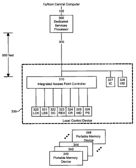
The structure of a local control device and a Dedicated
Services Processor, in accordance with the invention, that
implements the functionality of an local control device/SAC
combination is illustrated in Figure 3. Figure 3 shows a
distributed structure that includes a Dedicated Services
Processor (DSP) 300 that is located remotely from the
controlled access point, an Integrated Access Point Controller
(IAPC) 310 and a set of components 320 - 328 for data gathering
and for implementing certain functions at the controlled access
point. The IAPC 310 and the set of components 320 - 328 are
mounted locally in the vicinity of the controlled access point
and form the local control device 330. The DSP 300 is
essentially a bridge device that provides power and data
formatting and translation functions to the IAPC 310. It can
be installed in a service cabinet located at an intermediate
point between the IAPC 310 and a CACSC 100 such as in Figure
CA 02240881 1998-06-17
13
1. The IAPC 310 can be connected to the DSP 300 by a twisted
wire pair. The set of components 320 - 326 connected to the
IAPC 310 include a lock device (LCK) 320, a lock status sensor
(LSS) 321, a door contact sensor (DC) 322, a request-to-exit
device (REX) 323, a card reader device (CR) 324, a warning
device (WD) 325 and a manual pull-station (PS) 326. The
intercom (IC) 327 and the video camera (VID) 328 are connected
in directly to the twisted wire pair 305.
The operation of the IAPC requires the use of portable
memory devices 340 to 348 issued to respective users that may
hold for example 2K bits of data of schedule data, memory
address indexing, user ID #, user photograph, etc. A portable
memory device in the form of an access card that was used
successfully is available from Card Intell, Inc. under the
product number V4050. Details concerning the access cards are
provided later with Figure 5.
The DSP 300 and the IAPC 310 from Figure 3 are further
detailed in Figure 4. The basic components of an IAPC 310 are
a memory 450, a processor/controller 460 and a protocol
converter 470. The memory 450 holds, among other information,
the instruction set for the processor/controller 460, schedule
validation data for each user and a list of valid
identification numbers for this controlled access point. The
processor/controller 460 performs command and control functions
for all the incoming, outgoing and internal data. The
processor/controller 460 is implemented with an acceptance mask
that screen unwanted messages. The protocol converter 470
converts data to/from the data communication protocol for each
of the devices 320 to 326 to/from the data communication
protocol on wire pair link 305. The protocol converter 470 can
CA 02240881 1998-06-17
14
be implemented in software, however it is preferred to
implement this component in hardware.
The basic components of a DSP 300 are a memory 410, a
power supply unit 415, a processor/controller 420 and a
protocol converter 430. The memory 410 holds, among other
information, the instruction set for the processor/controller
420, and a transactions or events buffer. The power supply unit
415 is simply a battery used as a back-up power source. The
processor/controller 420 performs command and control functions
for all the incoming, outgoing and internal data. The
processor/controller 420 is implemented with an acceptance mask
that screens unwanted messages. It also integrates a Dynamic
Response System (DRS). The DRS is necessary in order to supply
the correct amount of power to the IACP 310. Power is lost on
link 305 due to wire resistance. For example, for a link 305
of 100 feet the DSP 300 may need to supply 16 volts in order
to get 12 volts at the IACP 310. In another situation the link
305 may be of 500 feet and, in this case, the DSP may need to
supply 24 volts in order to get the same 12 volts at the IACP
310. Therefore, in order to accommodate different link 305
lengths, the IACP 310 will measure the input voltage it
receives and advise the processor/controller 420 to raise or
lower its voltage. The protocol converter 430 converts data
to/from the data communication protocol on link 105 to/from the
data communication protocol on link 305.
A memory allocation for the 2K bits of data on any one of
the access cards 340 to 348 is shown in Figure 5a. In a
preferred embodiment, the memory contains a global set of
schedule data elements, the set containing eight individual
schedule data element fields 501 to 508. Each schedule data
CA 02240881 1998-06-17
element defines a time interval. The time interval definition
uses 4 bytes (32 bits) of data and it is made relative to a
start date stored in the field 509, and an end date stored in
a field 510. As such the start date and end date fields 509
5 and 510 do not form part of the global set of schedule data
elements, however this is not critical to the success of the
invention. It may very well be envisaged to integrate the
start date and end date fields to the schedule data elements.
The portable memory device also has a user identification field
10 511 to store a user identification number, a schedule
validation data field 512, a customer number field 513 and a
customer site field 514.
The remaining part 515 of the memory of each access card
15 340 - 348 may be used for things such as: a user profile that
may indicate user preferences (i.e. heating, air conditioning,
lighting, etc.) or privileges (i.e. arm or disarm); a
photograph of the user; a door open delay per user, which may
be necessary if some users require more time to access than
others; and a Personal Identification Number (PIN), which is
required if a code must be entered along with the card.
The stored schedule data elements 501 to 508 indicate the
times at which the user may potentially be authorized to enter
the premises at this location. An example of the bit
allocation for one schedule data element is shown in Figure 5b.
The first 8 bits (bits 0 to 7) are flags that indicate the days
of the week and holidays that are valid. Bits 8 and 9 are not
used. Bits 10 to 20 indicate the beginning of the time
interval while bits 21 to 31 indicate the end of the time
interval with reference to a 24 hour time frame. In a specific
example, the beginning of the time interval may be 09h00 while
CA 02240881 1998-06-17
16
the end of the time interval may be 17h00. In this example,
the time interval is the same for every day, however it may be
envisaged to use different time intervals for different days
of the week. This may be accomplished by using a more
elaborate data structure to store the additional information.
An example of a schedule is detailed in the table hereunder.
BIT VALUE REPRESENTATIOIZ
31-21 011 111 1100* To 17h00
20-10 010 0001 110** From 09h00
8-9 00 -
7-0 00111110*** Friday, Thursday, Wednesday,
Tuesday, Monday
Notes: * this is the number 3FC in hexadecimal form or
1020 in decimal, which is equal to 17X60 minutes
since o0h00.
** this is the number 21C in hexadecimal form or 540
in decimal, which is equal to 9X60 minutes since
OOhOO.
*** these are the flags for each day included in this
from-to schedule (i.e. a"i" indicates that the
corresponding day is valid).
In the example in the above table, the user is potentially
authorized to enter the premises on every day of the week
except Saturday and Sunday from 09h00 to 17h00.
The start 509 and end 510 dates are of the same format and
in a preferred embodiment this format is a shown in Figure 5c.
This figure simply shows a 32 bit format where bit "0" is the
Least Significant Bit (LSB) and bit 31 is the Most Significant
Bit (MSB). In their hexadecimal form, the 4 bytes (32 bits)
represent the count in seconds since 1 January, 1970.
CA 02240881 1998-06-17
17
Therefore, a bit allocation such as "0011 0101 0000 1011 0001
1010 0000 0000" is 350B1A00 in hexadecimal or 889,920,000 in
decimal, which represents 15 March, 1998 because, on that date,
889,574,400 seconds have past since 1 January, 1970. The data
in the start date field 509 and the end date field 510
establish boundaries in the time domain to control when one can
start using the card and when the card expires. This is simply
a mechanism to avoid releasing, to a user, a card that can be
perpetually used.
In a preferred embodiment, the format for the user
identification number 511 is shown in Figure 5c. This format
can therefore accommodate 232 (more than 4 billion) different
users for one Automated Access Control System. An example user
identification number would be "0001 0000 1110 0011 1111 0101
1001 1001".
The memory 450 of the IAPC holds a table that is organized
as follows:
IISSR ID NUMBSR SCFTSDULS VALIDATION FLAGS
0001 0000 1110 0011 1111 0101 1001 1001 11111111
0001 0000 1110 0011 1111 0111 1001 0000 00110000
0001 1100 1110 0000 1111 0101 1001 0111 11110000
0001 0000 1111 0011 0000 1100 1001 0001 10000000
The validation flags are used to determine which ones of
the individual schedule data elements stored on the access card
are valid. The validation mechanism involves the data stored
in the schedule validation field 512. For convenience, the
data stored in this field is identical to the user
identification number. Evidently, this is not a critical
requirement and one may very well envisage to use a schedule
CA 02240881 1998-06-17
18
validation data that is different from the user identification
number. In use, the IAPC scans the user access card and loads
in memory the data held in the memory of the access card. As
a first step of the validation process, the IAPC compares the
user identification number against a master list of user
identification numbers established as a being valid. In a
specific example this may involve simply searching the user ID
number field in the above table to determine if the number read
from the user access card is present. If the number is not
found, the operation is terminated and no authorization to
unlock the door is given. Otherwise, the IAPC proceeds to the
next step that determines if the user can be granted access to
the premises at the particular time the operation is being
effected. Essentially, this is determined by processing the
schedule data elements, the schedule validation data and the
schedule validation flags. These three elements of
confirmation establish the time intervals during which access
to the premises can be granted. Next, the system compares the
time intervals with respect to the system time to determine if
the transaction that it is being correctly effected falls in
any one of the authorized time intervals. In the affirmative,
the transaction request is validated and the door is unlocked
or more of generally, the desired action that is sought by the
user is completed.
In a preferred embodiment, the table includes an
information field mapped to the user identification number.
This information field contains eight schedule validation
flags, there being one flag associated with a given schedule
data element on the access card. In fact, this number could
be the same as for the user identification.
CA 02240881 1998-06-17
19
The data stored in the schedule validation flags field is
an eight bit data unit, each bit of this data unit being
associated with a respective schedule data element stored on
the access card. The state of each schedule validation flags
in the data unit determines whether the associated schedule
data element is valid for this user. For instance, the value
"0" indicates that the associated schedule data element is not
valid, while the value "1" indicates that the schedule data
element is valid. The schedule validation process thus consists
of extracting the schedule validation data from the memory of
the user access card and using that information as an index in
the table in the user ID number field. When the corresponding
record is found, the data unit in the schedule validation flags
field is extracted. The individual bits are then read and the
schedule data elements associated with the bits whose value is
"1" are marked or otherwise indicated as being the valid ones.
This operation amounts to defining from the global set of
schedule data elements stored on the access card a sub-set of
schedule data elements that are valid. In a specific example,
the first row of the table provides a 32 bit user ID number and
the associated schedule validation flags data unit is an eight
bit group where all the bits of are set to the value "1". This
means that all the schedule data elements of the global set are
valid. In the other words, the sub-set of schedule data
elements is identical to the global set of schedule data
elements. In the second row of the table, only two of the
eight bits are set to "1", thus, only the associated two
schedule data elements will be valid for this user. In this
specific example, the sub-set extracted from the global set of
schedule that elements has only two members.
One possible variation that may be considered is to omit
CA 02240881 1998-06-17
the schedule validation data provided on an access card and use
the user ID number for a dual purpose, namely as an identifier
of the user and also as an index to the table to extract the
correct schedule validation flags group. However, the approach
5 described earlier is preferred because it provides a greater
flexibility in that the system is not restricted to use
identical user ID numbers and schedule validation data.
The 4 bytes for the customer number 513 and the 4 bytes
10 for the customer site 514 are, again, in the format shown in
Figure 5c. This addditional information ensures that a user
cannot by chance have the same number as another user and enter
another site in the same company or for that matter any site
from another company.
As for the future use 515 memory allocation, it may
include additional features of an automated access control
system such as photo identification.
The communication protocol that was developed for the
preferred embodiment of this invention and that is used on link
305 is similar to the CAN electrical protocol or any other non-
destructive protocol. It is implemented as a half-duplex
connection; that is, only one node on the network may send
information and all are receiving it. As stated earlier the
protocol is used for power and data communication and uses a
single twisted wire pair. One wire is common while the other's
voltage level varies to represent different information. Two
possible embodiments for this data communication protocol are
described below. Both embodiments can accommodate up to seven
nodes on the network, but could be easily expanded.
CA 02240881 1998-06-17
21
Figure 6a illustrates a first embodiment of the data
communication protocol. Three voltage level are possible: the
high level 610 that represents a one, which is recessive, a low
level 612 that represents a zero, which is dominant, and
finally the power source level 600 provides power to all
network nodes. Also note that the low level 612 is used at the
beginning of each data communication to synchronize the nodes.
The Sync 602 uses 20% of the duty cycle 614. In an embodiment
of the invention, a duty cycle of 100 microseconds was used
successfully. Recessive 610 and dominant 612 bits need to be
defined in order to determine priority in case of message
collision. A bitwise arbitration approach is used to determine
which message has priority. That is, if a node reads a dominant
bit while it is transmitting a recessive bit, it will stop
transmitting immediately and release the bus. The result is
that the higher priority message is not lost. Before
transmitting, a node must therefore monitor the network to
verify if it is idle and wait for a Sync 602. The network is
in an idle state after a 2-bit duty cycle 614 at the power
source level 600.
Actual node data is being transmitted on the network
during the Write 604 or Read 606 portions of the duty cycle.
The Write 604 portion represents 40% of the duty cycle while
the Read 606 portion represents 30% of the duty cycle. The
remaining 10% of the duty cycle are reserved idle time 608
necessary for the release of the network back to the source
level 600. In order to ensure release of the network the idle
time is always at the recessive level 610 (i.e. a"one").
This example of the communication protocol is able to
communicate one bit of data at a time. In use it may represent
CA 02240881 1998-06-17
22
a value being written on the bus by a node (write 604) or a
value that was read from the bus by a node (read 606). A few
examples for bit transmissions follow. A node brings the
voltage on the bus to zero 612. All nodes synchronize their
clock by reading the falling signal. If the signal rises to
one 610 at the beginning of the write portion 604, this node
is writing a one on the bus. All nodes will read the rising
edge of the signal. If the signal rises to one 610 at the end
of the write portion 604, this node is writing a zero on the
bus. If the signal rises to one 610 at the beginning of the
read portion 606, this node is indicating that it read a one
on the bus. Finally, if the signal rises to one 610 at the end
of read portion 606, this node is indicating that it read a
zero on the bus.
Figure 6b illustrates a second embodiment of the data
communication protocol. In this embodiment, arbitration, bit
values 630 and 632, power source 620, sync 602, idle time 628
and duty cycle 634 are all the same. The only difference
resides in the data transmission. In this case, a value
represented by 8 bits of data is transferred during 0% to 90%
of the duty cycle 634 and this value is either being written
on the bus or an indication of a value read from the bus.
In this example of the data communication protocol, the
node clock rate is quite important. Eight bits of data can
represent 256 different values. Good results for reading the
bus falling or rising edge can be obtained by sampling twice
for each of the 256 values. This means that during the 90
microseconds that the 8-bit data is represented (90% of 100
microseconds), the bus is read 512 times or at a rate of
approximately 5.7 megahertz. Therefore, if, for example, a
CA 02240881 1998-06-17
23
node brings the voltage on the bus to zero 632, all nodes will
synchronize their clock by reading the falling signal. Then,
if the signal rises to one 630, at 78.125% of the 90
microseconds 8-bit data period, this means that a node is
writing (or showing that it read) 200 in decimal (78.125% of
256) or "1100 1000" in 8-bit binary format.
Considering that 20% of the duty cycle 634 is reserved for
sync 622 and that the sync is part of the 8-bit data period,
then the two least significant bits are sacrificed.
The above description of a preferred embodiment of the
present invention should not be read in a limitative manner as
refinements and variations are possible without departing from
the spirit of the invention. The scope of the invention is
defined in the appended claims and their equivalents.