Note: Descriptions are shown in the official language in which they were submitted.
CA 02241843 1998-06-29
WO 97/10476 PCTJUS96/14622
PLATE-TYPE CROSSFLOW AIR-TO-AIR
HEAT EXCHANGER IiAVING DUAL PASS COOLING
PACKGROUND OF THE INVENTION
1. Field of the Invention
= The present invention relates to an improvement in the
dehumidification of air through the provision of a plate-type crossflow air-to-
air
heat exchanger having a series of parallel plates enclosed in a housing which
forces
flowing air to be redirected for exhaust in a plenum chamber where it is
cooled in
a two pass flow path over a cooling coil which consists of a plurality of
cooling
conduits or tubes which are separated by and held as a single unit by a
multitude
of fins through which the conduits pass. The heat exchanger also allows a
regenerative heat exchange between the intake and exhaust airstreams of the
air-to-
air heat exchanger.
The invention further provides for the cooling coil to be arranged in
a manner in which the individual cooling conduits extend in a plane which is
parallel to a plane defined by the series of plates, while the fins and the
cooling
coil unit extends in a plane perpendicular to the plane defined by the series
of
plates. The cooling coil is positioned in the plenum chamber so that the air
flowing through the heat exchanger passes over the cooling conduits twice
before it
exits the housing. The invention further includes the provision of arranging a
number of the heat exchanger units in series utilizing a common cooling coil
and a
common plenum chamber to reduce the size of the system and the energy
requirements for operating the system to condition a large volume of air.
2. Discussion of the Prior Art
Conditioning of airstreams in residences and office buildings
typically requires relatively large amounts of energy to provide comfortable
ambient indoor air under a variety of weather conditions, depending upon the
climate and the season. Devices that cool and/or dehumidify air are well
known,
CA 02241843 1998-06-29
WO 97/10476 PCT/US96/14622
-2-
whereby as the air is cooled, moisture condenses out of the air resulting in
cooler,
drier air being returned to the ambient atmosphere. In the design of a
dehumidifying heat exchanger, an important question is whether, and how much,
heating will be applied to the air after it has been cooled for the purpose of
dehumidifying it. If the cooled, and thus dehumidified air is simply exhausted
into
the ambient indoor space without further heating, the process is one of
traditional
air conditioning. However, if after dehumidification, the air is reheated
before
being exhausted into the ambient space, the process will be one of traditional
dehumidification. Dehumidification is controlled by ambient humidity alone,
and
the unit is engaged and shut down on this criteria alone.
In the prior art, there exists a number of heat exchangers utilizing a
regenerative type of heat exchange airflow in which air is forced through the
housing in intake channels and then redirected into exhaust channels. Cooling
fluid conduits are provided so that the air passes over the conduits which are
typically arranged in a plane perpendicular to the channels and which are in
thermal contact with the walls defining the channels, such that the conduits
typically pass through the walls. An example of such a regenerative heat
exchanger is disclosed in U.S. Patent No. 2,128,641 to Folsom, which discloses
a
dehumidifier in which the walls between the channels serve as the heat
exchange
surface for the air as it passes through the intake channels, over the cooling
conduits, and then around the channel walls in a plenum chamber into the
exhaust
channels and back over the cooling conduits. The air is then exhausted back
into
the atmosphere through exhaust ports located adjacent to the intake ports at
the
first end of the unit.
U.S. Patent No. 4,761,966 to Stark teaches cooling and reheating
for dehumidification in a crossflow arrangement, as well as an air temperature
and
water temperature control system for high humidity locations such as indoor
pools.
CA 02241843 1998-06-29
WO 97/10476 PCT/US96/14622
U.S. Patent No. 4,517,810 to Foley et al. teaches regenerative heat exchange
using
a "run around loop", and Canadian Patent No. 470,100 teaches the use -of a
corrugated plate in a heat exchange element. U.S. Patent No. 2,093,725 to Hull
teaches the provision of cooling conduits sandwiched between the heat
conducting
walls of the heat exchanger.
In the prior art heat exchangers, there is generally required large
plenum space to convey the intake air to a cooling conduit or to convey
exhaust air
leaving the cooling conduit to the final pass through the regenerative heat
exchanger. The large plenum space in the prior art thus could be disposed
either
upstream of the cooling conduit or downstream of the cooling conduit.
Accordingly, prior art heat exchangers required a large area for installation,
and
also required an excessive amount of energy to force the air through the heat
exchanger. Efforts to reduce the plenum space, such as that shown in Folsom,
require that the cooling conduits be constructed to pass through the plates of
the
heat exchanger.
Volumetric efficiency quantifies the required equipment volume in
per unit of capacity at a given performance level. In plate-type crossflow air-
to-air
heat exchangers, to increase the volumetric efficiency and economy of the unit
the
smallest possible plate size should be used. However, crossflow heat
exchangers
with smaller plates generally require more length, i.e. more plates, to handle
air
volumes equal to that of units with larger plates. Increasing the plate size
will
require a larger installation space which may limit the performance of the
heat
exchanger. In addition, when using crossflow plate-type air-to-air heat
exchangers
with smaller plates, the length, or number of plates, typically exceeds the
plate
dimension. The cooling coil, as stated above, consists of a plurality of tubes
which are separated by a series of fins serving as a heat transfer surface for
the
tubes. Generally, cooling coils have many circuits, each circuit comprising a
CA 02241843 1998-06-29
WO 97/10476 PCT/US96/14622
multitude of cooling tubes connected in series, from entrance to exit, using U-
bends. Therefore, for economic and efficient cooling coil selection, the
cooling
tubes in the prior art tend to run substantially perpendicular to the heat
exchanger
plates. However, this arrangement requires that each cooling tube or tube
circuit
be separately balanced due to the temperature gradient across the coil
surface,
because the temperature leaving a crossflow heat exchanger varies in a
direction
parallel to the plates. As the coolant fluid passes through the tubes, it
absorbs heat
sufficient to cool the air which passes over the tubes, typically in the range
of
35 F to 50 F. As the heat is absorbed over the length of the tube or circuit,
it is
most efficient to have substantially equal temperature conditions, or
refrigerant
superheating, leaving each tube or circuit. In prior art heat exchangers, as
seen in
Figure 1, when the tubes are arranged perpendicular to the plates, the
individual
tubes or circuits see different temperatures in the airstream, requiring
manual, and
tedious, balancing of the individual tubes or circuits to ensure equal coolant
heat
absorption and temperature drops, and thus optimum cooling of the airstream.
If
the cooling coil of Fig. 1 were placed at the entrance to the exhaust side of
the
crossflow heat exchanger, performance would improve somewhat because there is
more room for mixing of temperature to occur in the plenum chamber. However,
the degree of mixing is unpredictable and would be irregular in a confined
space
such as the plenum chamber.
The novel heat exchanger for dehumidification of the present
invention obviates the disadvantages associated with the prior art, by
providing a
plate-type crossflow air-to-air heat exchanger having a plurality of plates
and a
cooling coil consisting of tubes and fins, in which the cooling tubes are
arranged in
a plane parallel to a plane defined by the plates of the heat exchanger, while
the
coil itself, as well as the fins, extends in a plane generally perpendicular
to the
plane defined by the plates. The cooling coil is located adjacent to but
spaced -_
CA 02241843 2007-06-01
-5-
from the heat exchanger walls while maintaining a seal between the intake
channels
and exhaust channels as will be described below, and is located in a plenum
chamber
which redirects the air back over the cooling coil so that a two pass
arrangement is
achieved as the air passes from the intake channels to the exhaust channels
for return to
the ambient atmosphere. The heat exchanger of the present invention also
facilitates
installation in a system which utilizes a number of small units which are
operated
utilizing a common cooling coil, and may also utilize a common plenum space to
reduce the size required for installation, and ultimately provide an
efficiently operating
and economical system for dehumidifying air in buildings such as homes and
offices.
SUMMARY OF THE INVENTION
In heat exchange systems, two airstreams are allowed to pass in channels
in close proximity to each other, where the channels are separated by a heat
conducting
channel wall which, on one side, comprises the heat conducting channel wall
for the
intake airstream and on the other side comprises the heat conducting channel
wall for
the exhaust airstream. By so arranging the flow of air, temperature difference
between
the intake air and the exhaust air provides for thermal transfer through the
wall with
heat naturally flowing from the higher temperature air to the lower
teinperature air.
In accordance with an embodiment of the present invention, there is
provided a system for conditioning an airstream, coinprising: at least one fan
for
forcing air through the system; a first heat exchanger having an intake port,
an exhaust
port, a plenum chamber remote from the intake port and the exhaust port, and a
plurality of heat conducting walls orthogonal to and aligned along a first
axis and
defining channels for passage of air from the intake port to the plenum
chamber and
from the plenum chamber to the exhaust port, alternating ones of the channels
defining
intake channels and exhaust channels, the intake channels being sealed from
the
exhaust channels except at the plenum chamber such that the intake channels
are in
fluid communication with the exhaust channels at the plenum chamber; at least
one
other heat exchanger having an intake port, an exhaust port, and having the
plenum
chamber remote from the intake port and the exhaust port, and a plurality of
heat
conducting walls orthogonal to and aligned along a second axis laterally
spaced from
the first axis, defining channels for passage of air from the intake port to
the plenum
chamber and from the plenum chamber to the exhaust port, alternating ones of
the
CA 02241843 2007-06-01
-5a-
channels defining intake channels and exhaust channels, the intake channels
being
sealed from the exhaust channels except at the plenum chainber such that the
intake
channels are in fluid communication with the exhaust channels at the plenum
chamber,
wherein the heat exchangers are positioned adjacent to each other; and a
common
cooling conduit located in the plenum chamber of the first heat exchanger and
the at
least one other heat exchanger; the cooling conduit being positioned adjacent
to and
spaced from the heat conducting walls of the first heat exchanger and the at
least one
other heat exchanger; and the cooling conduit being positioned in a plane
substantially
parallel to a plane defined by the plurality of heat conducting walls in the
first heat
exchanger and the at least one other heat exchanger.
In the present invention, the apparatus is utilized as a dehumidifier,
where the intake air is precooled in a regenerative heat exchanger and then
further
cooled through the provision of a two pass air cooling arrangement. The air
cooling
process naturally condenses water vapor entrained in the intake air, which
along with
condensed and condensing water, flows into a condensation collection area
which is
part of the plenum chamber at the closed end of the apparatus. Condensing
water drops
into a collection area while the cooled intake air is
25
CA 02241843 1998-06-29
WO 97/10476 -6- PCT/US96/14622
redirected from the intake direction of the airflow for a second pass through
the air
cooling arrangement. The exhaust airflow travels through the exhaust-channels,
of
which at least one wall of the channel represents the wail separating the
intake =
channel from the exhaust channel. Through this wall occurs the heat exchange
process, where the cooled and dehumidified air is then warmed to return to the
ambient atmosphere at a comfortable temperature.
The present invention utilizes sensors to variably and selectively
regulate and control the humidity of the air being exhausted from the unit.
Other
conventional controls may also be provided to operate dampers to control the
dehumidification or air cooling processes to provide the option of air
conditioning
in addition to dehumidification. The apparatus of the present invention
includes a
plurality of heat conducting walls arranged in side-by-side parallel
arrangement,
and the entire heat exchange plate arrangement has a generally square or
diamond
shape. The number of intake and exhaust channels is determined by the amount
of
plates provided, which is variable with respect to the installation in which
the heat
exchanger will be utilized. The square shape of the heat exchanger is
preferably
positioned on a point of the square, such that a diagonal running from one
corner
of the square to its opposite corner is generally vertical when the unit is
installed.
The heat exchanger plates, or heat conducting walls, are preferably
provided with means for enhancing the heat conduction process, such as heat
conducting spacers, or preferably, a series of corrugations which extend
between
the walls and are in thermal contact with each of the walls. The corrugations
serve the dual purpose of enhancing heat transfer between the walls to
facilitate the
heat exchange process, and also provide flow paths for the airstream to seal
the
intake channels from the exhaust channels. The preferred arrangement is a
crossflow arrangement, and in this arrangement, the corrugations for the
intake
channels are substantially arranged at right angles to the corrugations for
the
CA 02241843 1998-06-29
WO 97/10476 PCTIUS96/14622
exhaust channels, to define the flow path through the heat conducting walls so
that
the intake airflow is approximately 90 offset from the exhaust airflow.
The present invention includes a housing, having an intake port at
the proximal end which is located adjacent to the intake channels and in fluid
communication therewith, and also includes an exhaust port in fluid
communication
with the exhaust channels also at the proximal end. Located at the distal end
of
the housing is a plenum chamber, and inside the plenum chamber is a cooling
coil
having cooling conduits or tubes and thin walled fins extending between and
supporting the tubes, which pass through the fins. The coil further cools the
air
and condenses water vapor entrained in the air to dehumidify the air. The
cooling
coil is located adjacent to but spaced from the heat conducting walls of the
heat
exchanger, and the conduits or tubes are preferably arranged and extend in a
plane
which is parallel to a plane defined by the heat conducting walls. The cooling
coil
itself, and in particular the fins, extends in a plane perpendicular to the
plane of
the plates or walls, while maintaining the conduits in the same plane as the
walls.
This permits the air to flow uniformly over the cooling conduits to provide
for a
more efficient cooling process so that each tube and circuit sees
substantially the
same temperature profile.
A fan forces the airstream into the heat exchanger of the present
invention, as is conventional, through the intake ports so that the airstream
enters
the heat exchanger at the intake channels. As the airstream passes through the
intake channels, it is precooled through the heat exchange process with the
heat
conducting walls and the corrugations. The precooled air then exits the intake
channels and passes over the cooling coil to condense water vapor entrained in
the
airstream which is then collected in a collection chamber which is part of the
plenum chamber. The plenum chamber redirects the air so that it passes over
the
cooling coil a second time and enters the exhaust channels, where it is warmed
CA 02241843 1998-06-29
WO 97/10476 PCT/US96/14622
through the heat exchange process with the heat conducting walls and the
corrugations, prior to exiting the heat exchanger at the exhaust port. The air
exiting the heat exchanger of the present invention is thus cooler and drier
as it is
returned to the ambient atmosphere.
The present invention also contemplates the use of heat conducting
spacers instead of the corrugations in the intake channels and the exhaust
channels.
In this embodiment, the spacers are positioned in the channels to facilitate
the
assembly process of the heat exchanger and to enhance the heat transfer
between
the walls. In this embodiment, the exhaust channels must be sealed at the
intake
port and at the plenum chamber adjacent to the intake channels, and the intake
channels must be sealed at the exhaust port and at the plenum chamber adjacent
to
the exhaust channels. This will ensure the crossflow of the air and the two
pass
arrangement of the airstream over the cooling conduits of the coil as the air
is
forced through the heat exchanger for dehumidification.
A further embodiment of the present invention utilizes a plurality of
the heat exchanger units in a system which includes a cooling coil which is
common to each of the heat exchangers. The cooling conduits or tubes are
arranged in a plane parallel to a plane defined by the plates which form the
heat
conducting walls of each of the individual heat exchangers. It is also
contemplated
that the plenum chamber may be a common plenum chamber, in a system which is
utilized in a large installation.
The present invention provides a thermally regenerative heat
exchange system for dehumidification which is embodied in a novel assembly
which increases the efficiency and reduces the physical space formerly
required for
installation of prior art devices. By arranging the cooling coil so that the
cooling
conduits are parallel to the plane defined by the walls of the heat exchanger,
the
unit essentially becomes a self balancing system with respect to the coolant
fluid
CA 02241843 1998-06-29
WO 97/10476 _9- PCTIUS96/14622
passing through the conduits. The present invention is less expensive to
manufacture and easier to maintain, and the present invention also
accommodates
larger installations by providing a means for arranging a number of the heat
exchangers in series utilizing a common cooling conduit and a common plenum
chamber.
BRIEF DESCRIPTION OF THE DRAWINGS
The foregoing features of the present invention will become more
readily apparent and may be understood by referring to the following detailed
description of an illustrative embodiment of the heat exchanger for
dehumidification, taken in conjunction with the accompanying drawings, in
which:
Fig. 1 is a schematic representation of a prior art plate-type
crossflow air-to-air heat exchanger showing the flow path of the airstream;
Fig. 2 illustrates a preferred embodiment of the plate-type crossflow
air-to-air heat exchanger of the present invention;
Fig. 2a illustrates a side view of the heat exchanger taken 90 from
the view shown in Fig. 2, along lines 2a-2a of Fig. 2;
Fig. 3 illustrates a perspective view of the heat conducting walls and
the corrugations provided between the walls of the plate-type heat exchanger
of
Fig. 2;
Fig. 4 illustrates a side plan view of an alternate embodiment of the
heat conducting walls showing heat conducting spacers positioned between the
walls of the plate-type heat exchanger of Fig. 2;
Fig. 5 illustrates a perspective view of the heat conducting walls of
the embodiment of Fig. 4 showing the flow blocking plates;
Fig. 6 illustrates a system utilizing plate-type crossflow air-to-air
heat exchangers positioned in series according to the present invention; and
CA 02241843 1998-06-29
WO 97/10476 -10 PCT/US96/14622
-
Fig. 7 illustrates the system of Fig. 6 with modified intake and
exhaust flow paths.
DETAILED DESCRIPTION OF THE PREFERRED EMBODIMENTS
Turning now to the drawings, in which like reference numerals
identify similar or identical elements throughout the several views, Fig. 1
illustrates a plate-type crossflow air-to-air heat exchanger which is common
in the
prior art. Such a heat exchanger 10 includes a plurality of plates comprising
heat
conducting walls 12 through which the airstream passes. Heat conducting walls
12
are connected to a plenum chamber 14 which redirects the airflow as it enters
the
plenum chamber through the intake channels to be exhausted through the exhaust
channels and back into the atmosphere. As the air passes from the intake
channels
into the plenum chamber 14, the air passes through a cooling coil 16 which
includes a plurality of coolant carrying conduits or tubes 18 and a plurality
of thin
wall fins 19 extending the length of the coil through which the tubes 18 pass.
Tubes 18 are arranged generally perpendicular to a plane defined by the heat
conducting walls 12. As seen in Fig. 1, the airstream enters in the direction
of
arrow 20 and passes through the heat conducting walls 12 and into the plenum
chamber 14. The airstream then passes over the cooling coil 16 where water
entrained in the airstream is condensed out of the airstream and then the
airstream
is redirected by the plenum chamber and exits through the exhaust channels of
the
heat conducting walls 12 in the direction of arrow 22.
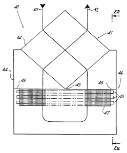
Fig. 2 illustrates the plate-type crossflow air-to-air heat exchanger
according to the present invention. As seen in Fig. 2, heat exchanger 40
includes
plate or wall assembly 41 which includes a plurality of heat conducting walls
42
which are attached to plenum chamber 44. In the present invention, the cooling
coil 46 is positioned so that coolant carrying tubes 48 are positioned in a
plane
CA 02241843 1998-06-29
WO 97/10476 PCT/US96/14622
which is parallel to the plane defined by the heat conducting walls 42. The
coil 46
itself, including fins 47, extends in a plane generally perpendicular to a
plane
defined by the walls 42. As seen in Fig. 2a, heat conducting walls 42 of heat
exchanger 40 extend in a plane generally parallel to a plane in which tubes 48
run.
Fins 47 run generally perpendicular to the plane walls 42 are located in.
Referring back to Fig. 2, as air enters the intake ports of the heat
exchanger housing (not shown) in the direction of arrow 50, it enters the
intake
channels of the heat conducting walls 42 and passes into the plenum chamber 44
where it passes over the cooling coil 46 for the first time. The coil is
secured to
the walls 42 at bead 43 which provides a seal to ensure that the airflow
passes over
the coil 46. Ledge members 45 serve a similar function. The construction of
the
plenum chamber redirects the airstream so that it passes over the cooling coil
46 a
second time prior to exiting the plenum chamber 44 through the exhaust
channels
and out the exhaust port of the heat exchanger in the direction of arrow 52.
As the intake airstream passes over the coil the first time, while it is
desirable for the temperature profile of the airstream to be as uniform as
possible,
there may be some variations due to temperature differences within the various
channels, which then passes over the various conduits, etc. The present
invention
permits the airstream to mix and reach a substantially uniform temperature in
the
plenum chamber. The airstream which then passes over the coil the second time
is
then more efficiently cooled due to the uniformity of the temperature. The air
passing to the exhaust channels of the prior art heat exchangers does not have
a
uniform temperature gradient and therefore is not as efficiently cooled as in
the
device of the present invention.
As seen in Fig. 3, wall assembly 41 includes the heat conducting
walls 42 which are positioned side-by-side in parallel arrangement, and
preferably
include a means for enhancing the heat transfer between the heat conducting
walls
CA 02241843 1998-06-29
WO 97/10476 -12- PCT/US96/14622
42. As shown in Figs. 2a and 3, preferably the means for enhancing heat
conduction comprises a series of corrugations 54 which are maintained in
thermal
contact with the parallel plates. The intake channels 53 include corrugations
which
pass in a first direction and the exhaust channels 55 include corrugations
which
pass in a direction substantially at right angles to the corrugations of
intake
channels 53. This substantially 90 arrangement between the corrugations
assures
that the flow of air on the intake side in the direction of arrow 50 flows
only
through intake channels 53, and that the air leaving the heat exchanger
through
exhaust channels 55 in the direction of arrow 52 exits only through exhaust
channels 55. This ensures that the heat exchanger operates with a crossflow
airstream to facilitate the heat exchange process at the heat conducting walls
42.
Fig. 4 illustrates an alternate embodiment of the heat exchanger in
which the heat conducting walls 42 are separated by heat conducting spacers 56
which enhance the heat transfer between the walls. Blocking members 58 are
provided in this embodiment which cover the exhaust channels 55 on the intake
side, and further are provided to block the intake channels 53 on the exhaust
side.
(The blocking members 58 on the exhaust side are not shown in Fig. 4 for
clarity.)
Turning now to Fig. 5, there is shown the embodiment of Fig. 4 with the
blocking
members 58 in place. Air entering the heat exchanger in the direction of the
arrow 50 on the intake side at intake channels 53 is prevented from entering
the
exhaust channels 55 by the blocking members 58, and after the air passes over
the
cooling coils (not shown) and is redirected in the plenum chamber, as at arrow
59,
to exit the heat exchanger in the direction of arrow 52, the blocking members
58
prevent the air from entering the intake channels 53 as the air flows through
exhaust channels 55 in that direction.
Fig. 6 illustrates the heat exchanger 40 utilized in a system which
permits a plurality of heat exchangers 40, 40a, 40b and 40c to be arranged in
CA 02241843 1998-06-29
WO 97/10476 -13- PCT/US96/14622
series arrangement to handle large volumes of air in an economical and
efficient
manner. In this embodiment, air enters each of the intake ports of the heat
exchangers in the direction of arrow 50, is precooled as it passes through the
intake channels 53 of heat conducting plates 42 and enters the plenum chamber
68
for further cooling and for condensing the water vapor entrained in the
airstream
as it passes over cooling coil 66. Walls 70 and beads 43 ensure that the
intake
airflow and exhaust airflow are not mixed prior to passing through coil 68.
The
air is then redirected as shown and passes over the cooling coil 66 a second
time
and re-enters the exhaust channels 55 of heat conducting plates 42 of the heat
exchanger to permit the transfer of heat in the heat conducting walls 42 to
warm
the airstream as it exits the heat exchanger in the direction of arrow 52. The
embodiment of Fig. 6 provides a common plenum chamber 68, as well as a
common cooling coil 66 as shown. Fig. 7 is similar to Fig. 6 except the intake
airflow and exhaust airflow are consolidated to eliminate several ports and to
enable the elimination of separating walls 70.
While the invention has been particularly shown and described with
reference to the preferred embodiments, it will be understood by those skilled
in
the art that various modifications and changes in form and detail may be made
therein without departing from the scope and spirit of the invention.
Accordingly,
modifications such as those suggested above, but not limited thereto, are to
be
considered within the scope of the invention.