Note: Descriptions are shown in the official language in which they were submitted.
CA 02243152 2003-05-06
DESCRIPTION
DIAPHYSIAL CORTICAL DOWEL
Backxaround of the Invention
i. Field of the Invention: "fhe invention provides a novel dowel machined from
the cortex
of bone diaphyses and methods of use thereof.
ii. Ba und: It is common for patients presenting with spinal trauma or
pathology to
require the fusia~n of two or more vertebra. In the art, a standard solution
to this problem is to create
a cavity between two adjacent vertebra to aooept the insertion of a dowel
made.from bone or another
material. For this purpose, a dowel ;lrnown as the Cloward Dowel has been in
use for mmy years.
That device is a generally circular pin made by drilling an allogeneic or
sutogenic plug from the
cancellous bone of the ilium (i.e., the hip bone). As such, this bone has two
cortical surfaces (i.e.,
it is bicmtical) and has an open, latticod or porous structure between the two
cortical surfaces.
Unfortunately, such dowels have very poor biomechanical properties,
principally being susceptible
to compnssian. Accordingly, such dowels present the major danger of collapsing
prior to fusion of
the adjacent vertebra be<wan which such a dowel is inserted.
A dowel of greater biamochaztical properties has bees produced from allogeneic
femoral or
tibial conldyles (i.e., the rounded prominence at the end of the femur or
tibia where such bones
ertica~late with other bones). The result of drilling a plug from such a
coadyle is a unicortical dowel.
Such unicactical dowels ate available from most tissue banks, including the
University of Florida
Tissue Bank, Inc., (see, far example, our Allograft Catalog, product numbers
280012, 280014, and
280016; this catalog and these products are available on request by calling
904-462-3097, or by
calling 1-800-0AGRAFT, or by writing to the University of Florida Tissue Bank,
Inc., 1 Progress
Boulevard., P.O. Box 31, S. Wing, Alachua, Florida 32615). While such
unicortical dowels
represent a major advance over the bicortical dowels of Cloward, described
above, from a
biomechanical point of view, the biomechanical properties of the diaphysial
cortical dowel of the
instant invention is expoc~d to rat a substantial improvement over the
unicortical dowels, due
to the greater density of source bone, as will be evident from a reading of
the full disclosure which
follows.
CA 02243152 2003-05-06
2
In addition to the known ~;loward and unicortical dowels, a number of United
States Patents
have beers found dealing with the general area of dowels for achieving
vertebral fusions. Thus, for
example, U.S. PateW No. 5,0I5,247 discloses a threaded spinal implant which,
when placed between
two adjacent vertebrae, directly participates and is inwrporated in the
ensuing fusion. The implant
is made of a hollow metal casing which is filled with osteogenic material. A
plurality of perforations
are provided in the casing so that bone can grow into and out of the implant.
Metal threads and tabs
are provided to insc,~rt and prevent backing out of the implant, respectively.
However, that implant
is made out of metal and thus is a foreign object which is inserted into the
spine and is thus never
fully incorporated into the fusion. Furthermore, as the implant is preferably
made of titanium,
production of the implant requires the use of specialized metal molding and
machining, and
production of the implant material itself, which is expensive.
In U.S. Patent No. 4,6?7,853, a method of producing a prosthesis for
replacement of
articular cartilage and the prostheses so produced is disclosed. The
prostheses of the '853 patent,
principally designed for articulating cartilage replacement, are anachined
from allogenic or
xenogencic bone segments and then demiz~alized to produce a bone fragment with
a spongy texture
similar to natural cartilage. The prostheses are also farmed to render the
material non-antigenic.
While the methods of the '853 patent may be used to alter the properties of
the diaphysiai cortical
dowel of the instant invention, thre '853 patent does not teach or suggest the
novel device and
method of the instant invention.
In U.S. Patent No. 5, 03,049, a flexible prosthesis and a method for making
such
prostheses are disclosed. 'The pry inchuies machining a bone, demineraliziag
the bone to impart
a desired degree of flexibility, and tanning to render the material non-
antigenic. This patent is
gay ~ ;a a to the di,ae found in the '853 patcat discussed above, except that
the particular applicability of the disclosed process to the production of an
outer ear prosthesis is
emphasized.
In U.S. Patent No. 5,306,303, a bore induction method is disclosed which
consists of
implanting a bone morphogrnetic, protein-free cxraanic in the soft tissue or
bore of an animal. The
ceramic disclosed as preferable is calcium phosphate and the use of such
material for achieving
spinal interveatebral joist fusions (disk arthroplasty) is suggested. The
material and product of the
'303 patens, aside from its possible use for a purpose similar to that for
which the instant product is
designed, bears little or no resemblance to the instant invention.
In U.S. Patent No. 5,171,279, a method for subcutaneous suprafascial pedicular
internal
fixation of vertebra; of the spine is disclosed to facilitate graft fusion.
The method included excision
CA 02243152 1998-07-15
WO 97!259'15 PCT/US97/00630
3
of the uucieus of an affected disc, preparation of a bone graft,
instrumentation of the vertebrae for
fixation, and introduction of a bone gra$ into the resected nuclear space.
Metallic fixation hardware
is disclosed as the principal aspect of the claimed invention. Accordingly,
aside from dealing with
the same general problem, the invention disclosed and claimed in the '279
patent bears Little
resemblance to the diaphysial cortical dowel and method of the instant
invention.
Accordingly, having reviewed many solutions attempted in the field prior to
the instant
disclosure, it is concluded that there remains the need for a vertebral fusion
graft which has superior
biomechanical and vertebral fusion promoting properties. The instant invention
provides such a
graft as well as a method for making and using the graft.
Brief Summary of the Invention
The diaphysial cortical dowel of this invention is a graft useful in cervical
or thoracic and
Lumbar fusions. For cervical fnsions, the dowel is preferably obtained from
the allogeneic fibula,
radius, ulna and occasionally, from small humeri. The dimensions of such
dowels are typically
between about 8-15 mm in length (depth) and about 10-14 mm in diameter. For
thoracic and lumbar
fusion.C, the dowel is preferably obtained from the humerus, femur or tibia.
The dimensions of such
dowels are typically between about 10-30 mm in length (depth) and about 14-20
mm in diameter.
In each case, the dowel is obtained as a transverse plug from the diaphysis of
these bones.
Accordingly, each dowel has the feature of having the natural infra-medullary
canal of the source
bone forming a cavity through the dowel, perpendicular to the length of the
dowel, which can be pre-
packect with allogeneic cancellous bone, autogenous bone fragments,
hydroxyapatite, bioglass,
mixtures of these elements or any other bioceramic or osteogenic material to
promote rapid fusion
of the vertebrae between which the dowel is inserted. Such dowels are
generally referred to herein
as "diaphysial" cortical dowels. Unlike prior bone grafts, the present
invention provides a generally
cylindrical dowel of cortical bone having a canal through the dowel generally
perpendicular to the
long a~;is of the dowel.
The method for preparing and using the diaphysial cortical dowel of this
invention
comprises the steps of obtaining a plug from the diaphysis of an appropriate
donor bone or a plug
from an alternate acceptable cortical bone source through which a
perpendicular canal may be
machvied. Typically, the donor will have been extensively screened for
communicable diseases,
cancer, and at-risk behavior prior to acceptance of the donor bone for dowel
formation. The plug
is then, machined, preferably in a class 10 clean room, to the dimensions
desired. Optionally, a
groove is inscribed on the circumference of the dowel to prevent backing-out
of the dowel. Another
option is to inscribe a thread onto the cylindrical surface (circumference) of
the dowel to improve
CA 02243152 1998-07-15
WO 97/25945 PCT/US97/00630
4
fixation and prevent backing out. Chamfering of the forward end of the dowel
which is to be inserted
into a cavity formed between adjacent vertebrae is also preferred. The
curvature of the chamfered
end aids in the ease of insertion. Preferably, an instrument attachment hole
is machined in the
opposite end of the dowel from the chamfered end. Preferably, a score mark is
inscribed on the
cortical end into which the instrument attachment hole is machined so that the
surgeon can align the
infra-meduklary canal so that the canal is parallel with the length of the
recipient's spinal column.
In use, the surgeon creates a cavity between two adjacent vertebra that are to
be fused. The
autogenous bone fragments may be collected and packed into the infra-medullary
canal of the
diaphysial cortical dowel, or the dowel may be used with a pre-packed
osteogenic composition. The
dowel is mounted on an instrument via the instrument attachment hole and
carefully inserted into the
cavity created between the adjacent vertebrae to be fused. Over a period of
several months, it is
found that substantial fusion of the adjacent vertebrae occurs.
Accordingly, it is one object of this invention to provide a diaphysiak
cortical dowel made
from bone for insertion between vertebrae to be fused.
Another object is to improve patient incidence of safe and satisfactory
fusion.
Another object of this invention is to provide a dowel for vertebral fusions
which has
improved biomechanical properties over standard Cloward Dowels and unicortical
dowels known
in the art.
Another object of this invention is to provide a dowel with improved
osteogenic and
vertebral fusion promoting capacity.
Another object of this invention is to provide a dowel with a natural canal
running
therethrough to accept packing having osteogenic properties.
Another object of this invention is to provide a method for making a novel
diaphysial
cortical dowel.
2S Another object of this invention is to provide a method for using the novel
diaphysial
cortical dowel of this invention.
Additional objects and advantages of the diaphysial cortical dowel of this
invention will
become apparent from the full disclosure which follows.
Brief Summary of the Figures
Figure 1A depicts the structure of a standard unicorticak dowel known in the
art.
Figure 1B depicts the structure of a standard Cloward Dowel known in the art.
CA 02243152 1998-07-15
WO 97/25945 PCT/US97/00630
Figure 1C depicts the structure of one embodiment of the diaphysial cortical
dowel of this
invention.
Figure 2A depicts the ACF dowel with the instrument attachment hole and score
mark.
Figure 2B depicts the ATIF or ALIF dowel with the instrument attachment hole
and score
5 marl:.
Figure 3A and 3B depict one embodiment of this invention in which the dowel is
threaded.
Figure 3C and 3D depict one embodiment of this invention in which the dowel is
grooved.
Figure 4A is a side view of a dowel "blank" of this invention.
Figure 4B is an end-on view of the dowel "blank".
Figure SA is a threaded dowel of this invention.
Figure SB is an end-on view of the threaded dowel.
Figure SC is a detail of one embodiment of the thread of one embodiment of the
threaded
dowel of this invention.
Figure 6A is a top plan view of one embodiment of a dowel threader of this
invention.
Figure 6B is a side view of the dowel threader of this invention.
Figure 6C is an end-on view of the dowel threader of this invention showing
the elements
of the cutter assembly.
Figure 7A is a detailed view of a single tooth of one cutter blade of the
dowel threader.
Figure 7B is an end-on view of the tooth profile.
Figure 7C is a global side view of a cutter blade.
Figure ?D is a detailed side view of cutter blade 421.
Figure ?E is a detailed side view of cutter blade 422.
Detailed Description of the Invention
The diaphysial cortical dowel of this invention is a graft useful in cervical
or thoracic and
lumbar fusions. For cervical fusions, the dowel is preferably obtained from
the fibula, radius, ulna
and occasionally, from small humeri. The dimensions of such dowels are
typically between about 8-
15 mm in length (depth) and about 10-14 mm in diameter. For thoracic and
lumbar fusions, the
dowel is preferably obtained from the humerus, femur or tibia. The dimensions
of such dowels are
typically between about 10-30 mm in length (depth) and about 14-20 mm in
diameter. In each case,
the dowel is obtained as a transverse plug from the diaphysis of these long
bones. Preferably, the
bone plug.; are obtained using a diamond or hard metal tipped cutting bit
which is water cleaned and
cooled. (:onunercially available bits (e.g core drills) having a generally
circular nature and an
internal v~icant diameter between about 10 mm to about 20 mm are. amenable to
use for obtention
_. ,ø~ Sa.~.SUBST1TUTE._SHEET (RULE 26)
CA 02243152 1998-07-15
a
G
of these bone plugs. Such cure drills arc available. for example, ti~om
Starlite, Inc. A machine for
obtention of cndu- and cur'tla,ll duw'cls consists of a pneumatic driven
miniature lathe which is
fabricated li-om stainless steel and anodized aluminum. It has a spring loaded
carriage which travels
parallel to the cutter. The carriage rides on two runners which are I .0 inch
(?.~-t cm) stainless rods and
has a travel distance of approximately 8.0 inches (?0.33 cm). One runner has
set pin holes on the
runnin~~ rod which will stop the carriage from movin~~ when the set pin is
placed into the desired hole.
The carriage is moveable from side to side with a knob which has ~~raduatiuns
in metric and in En~~lish.
This allows the 'raft to be positioned. On this carriage is a vice with clamps
the ;raft and holds it in
place while the dowl is b~in~~ cut. The vice has a cut out area in the jaws to
allow clearance for the
cutter. The lathe has a drive system which is a pmumatic motor with a valve
controller which allows a
desired RPM to be set.
First, the carria~=a is manually pulled back and lucked in place with a set
pin. Second, the
=raft is loaded into the vice and is alit=ned with the cutter. Third. the
machine is stared and the RPM is
set. by using, a f~nob on the valve control. Fourth. the set pin, which allows
the graft to be loaded onto
I~ the cutter to cut the dowel. Once the cutter has cut all the way through
the ~~raft the carria~~e will stop
a
on a set pin. Fifth. sterile water is used to eject dowel out of the cutter. ;
It is fully autoclavable and has
a stainless steel vice and'ur clamping fixture to hold ~gratts for cutting=
dowels. The 'raft can be
positioned to within 0.001" (0.03 mm) of an inch which creates dowel
uniformity durin~~ the cutting
process.
''0 The cutter used in conjunction with the above machine can produce dowels
ran~~in!; from ~
mm to 30 mm diameters and the sizes of the cutters are 10.6 mm: I I.0 mm. 1
~'.0 mm: 13.0 mm: I-t.0
mm: 16.0 mm: and 18.0 mm. The composition of the cutters is stainless steel
with a diamond powder
cuttings surface mhich produces a very smooth surface on the wall of the
dowels. In addition. sterile
water is used to cool and remove debris from draft and!ur dowel as the dowel
is bein' cut (hydro
~5 infusion). The water travels down throu~'h the center of the cutter to
irr~~gate as w~el( as clean the dowel
under pressure. In addition. the water aides in ejecting the dowel from the
cutter.
Plu~'s having' a depth of about 8 mm to about 30 mm are generally acceptable,
with
appropriate gradations in length and diameter naturally being available at the
option of the machinist.
Accordingly, for cervical dowels. also referred to herein as anterior cervical
fusion or ACF dowels.
30 len~~ths of 8 mm, 9 mm. up to about I ~ men are desirable. Dowels of
ditTerin~ diameter are most
conveniently obtained as follows:
Diameter Source
10.6-I I mm fibula
se
~,~~r,~s~~~~ SHEET
CA 02243152 1998-07-15
WO 977259415 PCT/US97/00630
_ 7
I2 mm radius
I4 mm ulna
14+ mm small humeri
Dowels for thoracic and lumbar fusions, also referred to herein as anterior
thoracic inner
body fission (ATIF) and anterior lumbar inner body fusion (ALIF) dowels,
respectively, having a
depth of between about 10 - 30 mm, and preferably between about 15-24 mm, are
generally
acceptable, depending on the needs of a particular patient. Dowels of
differing diameter for thoracic
and lumbar fi>sions are most conveniently obtained as follows:
Diameter ours
14-16 mm humerus
16-18 mm femur
I8-20 mm tibia
In every case, a consenting donor (i.e., a donor card or other form of
acceptance to serve as
a donor) is screened for a wide variety of communicable diseases and
pathogens, including human
immunodeficiency virus, cytomegalovirus, hepatitis B, hepatitis C and several
other pathogens.
These tc,~sts may be conducted by any of a number of means conventional in the
art, including but not
limited oo ELISA assays, PCR assays, or hemagglutination. Such testing follows
the requirements
of (l) American Association of Tissue Banks, Technical Manual for Tissue
Banking, Technical
Manual - Musculoskeletal Tissues, pages M19-M20; (ii) The Food and Drug
Administration,
Interim. Rule, Federal Register / Voi. 58, No. 238 / Tuesday, December 14,
1993 / Rules and
Regulations / 655 l 7, D. Infectious Disease Testing and Donor Screening;
(iii) MMWR / Vol. 43
/ No. RR-8, Guidelines for Preventing Transmission of Human Immunodeficiency
Virus Through
Transplantation of Human Tissue and Organs, pages 4-7; (iv) Florida
Administrative Weekly, Vol.
I0, No. 34, August 21, 1992, 59A-L001-OI4 59A-1.005(12)(c}, F.A.C., (12) (a) -
(h), 59A-
1.005(15), F.A.C., (4) (a) - (8). In addition to a battery of standard
biochemical assays, the donor,
ar their next of kin, is interviewed to ascertain whether the donor engaged in
any of a number of high
risk behaviors such as having multiple sexual partners, suffering from
hemophilia, engaging in
intravenous drug use etc. Once a donor has been ascertained to be acceptable,
the bones useful for
obtention of the dowels as described above are recovered and cleaned. The f
nal machined product
may be stored, frozen or freeze-dried and vacuum sealed for later use.
Since the dowels are obtained from transverse plugs across the diaphysis of
long bones, each
dowel has the feature of having the natural infra-medullary canal of the
source bone forming a cavity
through the dowel perpendicular to the length of the dowel. The canal cavity
in the long bone is, in
vivo, filled with bone-marrow. in the standard Cloward Dowel and unicortical
dowels known in the
CA 02243152 2003-05-06
art, no such natural cavity e~sts and the cancellous bone that forms the body
of such dowels tends
to be too brittle to accept machining of such a cavity. The instant dowels, by
the nature of their
origin, are almady available with such a cavity. Naturally, based on this
disclosure, those skilled in
the art will recognize that other prone sources could be used which do not
have the infra-medullary
canal, and if su~cie;nt strength is inherent to the bone, such a canal could
be machined. Accordingly,
such an extension of this invention should be considered as an obvious variant
hereof and comes
within the claims appended hereto. The marrow is removed from the infra-
medullary canal of the
diaphysial plugs and the cavity is cleaned. The cavity can then be packed with
autogenous bone
&agmeuts from the recipient (i.e., when the cavity between adjacent vertebrae
is formed, the removed
bone fragments can be used as an autogenous packing), hydroxyapatite,
BIOGLASS~, mixtures of
these elements or any other osteogenic material to promote rapid fusion of the
vertebrae between
which the dowel is inserted. Bioactive glasses are generally composed of SiOz,
Na,O, CaO, and
P205. A preferred bioactive glass, BIOGLASS~ 4555 contains these compounds in
the following
respective weights: 45%, 24.5%, 24.4%, and 6%. As is evident from a review of
Arr Introduction
to Bioceramics, edited by Larry L. Hench and June Wilson (World Scientific
Publishing Co. Pte.
Ltd, 1993, volume I), there is a vast array of bioceramic materials, including
BIOGLASS~,
hydroxyapatite and calcium phosphate campositions known in the art which can
be used to
advantage for this purpose.
The methcxl for preparing and using the diaphysial cortical dowel of this
invention
comprises the steps of obtaining a plug from the diaphysis of an appropriate
donor bone. As
describai above, the donor will have been extensively screened for
communicable diseases, cancer,
and at-risk behavior prior to acceptance of the donor bone for dowel
formation. The plug is then
machined, preferably in a class L O clean room, to the dimensions desired. The
machining is
preferably conducted on a Iathe such as a jeweler's lathe or machining tools
may be specifically
designed and adapted f~ this purpose. Specific tolerances for the dowels and
reproduceability of
the product dimensions arse important features for the sucetssful use of such
dowels in the clinical
setting. Optionally, a groove 3Z (see figure 3B) is inscribed on the
cylindrical surface
(circumference) of the dowel to prevent backing-out of the dowel, thereby
foaming a "rib" on the
dowel which acts as a stop. Another option is to inscribe a thread 31 {see
figure 3A) onto the
circumference of the dowel. Machining of such grooves and threads on standard
Ctowai~d Dowels
and even on unicortical dowels known in the art is difficult if not impossible
due to the brittle
cancellous nature of'such dowels. Accordingly, the dowels of this invention
have the advantage of
having very good biomechanical properties amenable to such machining.
CA 02243152 2003-05-06
The forward end of the dowel which is to be inserted into a cavity formed
between adjacent
vertebrae is preferably chamfered by appropriate abrasive means known in the
art such as machining,
filing or sanding. 'fhe curvatwc of the chamfered end aids in the ease of
insertion. The tolerance
for the chamfering is fairly liberal and the desired object is merely to round
or slightly point the end
of the dowel that is to be inserted inta the cavity formed between adjacent
vertebrae to be fused.
Preferably, opposite the chamfered end, an instrument attachment hole is
machined, for
example by drilling andJor tapping. It is preferable that this end have a
generally flat surface to
accept the instrument for insertion of the dowel into the recipient.
Preferably, the dowel will be of
such dimensions as to fit standard insertion tools, such as those produced by
Midas-Rex, Inc. In
addition, it is preferred that a score mark be inscribed on the instrument
attachment site of the dowel
so that the surgeon cut align the infra-medullary canal so that the canal is
parallel with the length of
the recipient's spinal column. With the aid of the scare mark, once the dowel
is inserted into the
intervertebral cavity that is formed by the surgeon, and the canal is no
longer visible, proper
alignment is possible.
Referring W Figure 1, there is shown, in Figure 1A the standard unic~tieal
dowel 100
hwn in the art, having a cortical surfaoc 10, a drilled and/or tapped inset
attachment hole 15,
and a body of brittle: cancellous bcane 20.
In Figure 113, thane is shown the standard bicortical dowel 200 known in the
art having two
cortical surfaces 10,, a drilled andlor tapped instrument attachment hole 15,
and a body of brittle
cancellous bone Z0.
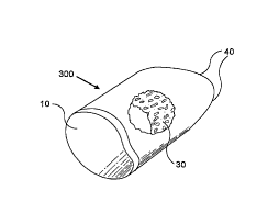
In Figure 1 C, one embodiment of the novel dowel 300 of this invention is
shown having a
cortical surface 10 into which an ir~stnmnent attachment hole 15 and aligtun~t
score mark 16 may
be machined (not shown as these elemtnts are optional but preferned). Also
shown is the
inlary canal 30 and the chamfered insertion exrd 40 (also optional but
preferred). Also not
shown but easily i»ribod dire to the str~g~ of the dowel 300 are
citcumferaitial (annular) ribbing
or threads.
Rcfemng to Figure 2, there is s6awn the ACF dowel in Figure 2A and the ATIF or
the ALIF
in Figure 2B. Also shown, in additbon to what is shown in Figure 1, arc the
score mark 16 and
the iast hole 15.
In figures 3A and 3B, the threaded 31 and grooved 32 dowel of this invention
are shown.
While those skilled in the art would know how to prepare a grooved or threaded
dowel of this
invention based on the foregoing disclosure and the disclosure of U.S. Patent
No. 5,814,084, one
specific technique tim preparation of~ preferred embodiments of this invention
is discussed herewith.
With reference to Figure 4A, there is provided a side view of a diaphysial
cortical
CA 02243152 1998-07-15
dowel of this invention, which may be used as is. ur which may b a Ilunhvr
machined to have ~.:rouves
or threads. For purposes of illuswatiun only, specific dimensions ufduwel
diameter. length and tlwead
pitch are provided. Those skilled in the art will reco~,niae that thw
specifics may be appropriately
scaled, depending un the size of the dowel required tbr any ~_imn application.
5 In the schematic view provided in tiuure -tA, a blank Juml is reprzsented
which may be
used to machine an I 8mm diameter by 28mm Iw~~th threaded duwc:l. Various
features of the dowel
blank are shown: the cortical bon a 10. the tapped instrument attachment hole
15. the infra-medullary
canal 30, and the chambered forward and of the dowel. -l0. Fur illustrative
purposes. the following
dimensions are also provided in inches and.'ur millimeters: 50 - 0.630" (
l6.Omm): 51 - 0.100"
10 (3.~-lrnm): ~.2 - 3.~ I''" ( f 3mm): ~3 - 1.03-4" (?6mm): ~.1- 0.60" ( I
.3nun); ~~ _ 0.1 ~Gl" (3.8nun):
56 - 0.317" (~.~mm).
In fissure -tB, an end-un view ufthe dowel blank turn thv inau~ument-
attachment pule 15
(rear) end ofthe dowel is pruv ided. For illustrative purposes, the following
dimensions are provided:
57 - 0.7087" ( 18mm).
I~ r In figure ~A. there is provided a view of the threaded dowel. Fur
illustrative purposes. the
1
follow ing dimensions are provided:
For the intramedullary cana1.30 a re_ular or irregular hole having! a diameter
s8 no greater than about
0.~~ 1" ( I-tram) is preferred to avoid the walls of the dowel ti-um bein';
too thin. and so that a
minimum wall thickness 59 at the rout ufthe thread. un both sides of the
canal. is preferably -tnun or
more. In ti~~ure ~B. an end-un view, ti-om the orientation ofthe double arrows
shoran. shows the
instrument attachment hole 1: and score mark l6 ur driver clot ,6. In figure
~C. there is shown a
detail ofone embodiment of the thread. In this embodiment. a ri~~ht hand
thread with ten threads per
inch at a heli~c angle at the root diameter ofabout 2.8892° is provided
as follows: the pitch 60 -
0. I Op" (2.6mm); the thread an~~le 61 - 60°: the thread crest width
62a - 0.025' (0.6-fmm): the thread
hei~_~u 63 0.039" ( I mm): and the radius of the various thread an~_le as it
changes 6-1 is typically about
0.010" (0.35~tmm). Those skilled in the art will recognize that the
fore~'oin'; specifics. '.v;i:e
preferable, may be modified depending= on the particular sur';ical requirement
ofa liven application.
Those skilled in the art will also recognize that any number of different
means may be
employed to produce the threaded or grooved embodiments of the dowel of this
invention. However.
in one preferred embodiment, with reterencv to figure 6A, there is shown a top
view ofa thread cutter
-100. in this embodiment. there is provided a handle -tU 1 attached to a drive
shaft .102 having a
threaded portion -t03 or a graduated sediment means ter controlled incremental
advancement of thv
drive shaft -102 upon rotation of the handle -401. Support tmans -40-t and -
405 are provided for
ali~=nment and support ofthe shaft -t02. with either ur both support means
having mat=hind threads.
3~ (in this illustration. only support means -l05 would hove matching threads,
while support means -t0-1
~t t~l,,tnri'1 ~~C~~
~I'. .: i: JJ
CA 02243152 1998-07-15
WO 971259.45 PCT/US97/00630
11
would have a hole which may have bearings to assist in rotation of the handle
401 and shaft 402),
or like graduated segment means for controlled incremental advancement of the
drive shaft 402. At
the terminal end 406 of the drive shaft 402, there is provided a protruding
element 407 which
corre;;ponds in width to the driver slot 56 on the rear end of the dowel of
this invention. At 408,
there is provided a housing for the cutter assembly described further below.
The supports 404 and
405 and the housing 408 for the cutter assembly are all mounted on a steady,
solid, preferably
weighty base unit 409 via screws, welding, or like attachment means at 410 a-
f.
Referring now to figure 6B, there is provided a side view of this embodiment
of the thread
cutter 400, with like elements described above being similarly numbered. The
following additional
elemelits are evident from this view: cutter blades assembly 420 (comprising
cutter blades 421 and
422 arid guide plates 424 and 425, see Figure 6C), is shown afFxed to the
cutter assembly housing
408, and an approximate travel distance 41I from the fully backed out terminal
end of the drive shaft
406, to the end of the cutter assembly 420 is shown. This distance must be
sufficient to allow
insertion of a dowel blank and advancement of the blank through the cutter
assembly 420 to allow
a fully threaded dowel to emerge from the cutter assembly.
In figure 6C, an end-on view (from the direction shown by the double arrows in
Figure 6B)
of the cutter assembly 420 and cutter assembly housing 408 is provided. The
elements of this
embodiment of the cutter assembly are now described in further detail:
corresponding 421 and 422
cutter blades are held in place in the housing 408 by fixation wedges 423a and
423b while guide
plates 424 and 425, having no cutting teeth, are held in place by fixation
wedges 423c and 423d.
Fixation wedges 423a-d are held in place by screws 426a-d. The foregoing
arrangement is
preferred, as it allows for easy disassembly of the cutter assembly, removal
of the cutter blades,
cleaning of the various components, and if desired, sterilization by
autoclaving, chemical, irradiative
or like means. It should be noted that the cutter blades 42I and 422 and guide
plates 424 and 425
may b~, fixed in place by increasing the tension created by tightening screws
426a-d, which draws
the fixation wedges 423a-d into the housing 408, thereby clamping these
elements in place.
Naturally, based on this disclosure, those skilled in the art will be able to
develop equivalents of the
cutter ~~ssembly system described herein, such as by use of wing-nuts, welding
or like means to affix
these various elements in appropriate cutting relationship to each other,
without departing from the
heart of this invention.
For purposes of illustration, the following additional features shown in
figure 6C are noted:
the diameter of the dowel that may be threaded according to this device is
defined by the diameter
of the aperture 427 created between the cutter blades 421 and 422 and the
guide plates 424 and 425.
It will be recognized by those skilled in the art that all of the foregoing
elements should preferably
~' !~ js!'~f3 j'1 ~. ~~~:~2_~.~~t~'v'~~4~~
. CA 02243152 1998-07-15
I?
be ma«ufactured from durable nutterials smh as -l-t0 stainless sml. ur like
materials. In particular. the
cuttings surfaces -121a and -t22a ut the blatlm -42! antJ -t22. ~Iwribud in
~ruate;r ~ictail below. ,tre made
from hard metal. It should further he: noted that tht: cutting ~d~~es -121a
and -1''?n are disposed in'
relation to each other so that thm ore un axis.
With reference to figure 7. greater dW ail regarding the cutW r blade, 421 and
-t'_. is providW:
Figure 7A provides a detail of the cutter. which maintains trw tooth IUI'ITl
tivm top to bottom. sU that Ilte
cutter can be sharpened by surface ~=rindin '= the lace. This is achieved by
wire-cutting=the teeth such
that tht:re is about a ~° incline 62c beUveen the dcscendin'~ vertices
at the li-ont and rear uFeach tooth,
l0 and about an :3° incline 62d bmveen the liwnt and rear uf~the top
ufeach tuutlt. This aspect can best he
seen in cutter blade end-un v iew 'L3. Also. the thicl.ness ufthe cutter
blade. 62e. preferably about
0.100' (~'.5-Imm), can be seen in that ti~_ure.
As noted in ti~=ore >C. thmn~=le 61 in ti~ure 7A is preferably about
60°. The w idth of the top
of the tooth 62b is preferably about 0.0'_x" (0.63~mm). The pitch 60 is
preferably about 0.100"I
(?.~mrn). tn ti~~ure 7C, there is shown an overall view ut the cutter blades -
421 ur 42? which are
assembled in tln~ cutter assembly h~u5in~ 408. Fur illustrative purpo,es. the
fullowin~; dimensions are
provid:d: The entire lun~th of the cu«er blade 421 b is about I .6>0"' (-
1.=cm). Fixation win ~s 421c and
-t21 d are provided to allwv proper seatin_~ uFthe cutwr blade upon insertion
into the housing -408. r1t ~,
a line is provided on cutter blades 42land 422. which allows tar appropriate
registration between cutter
blades 421 and 4~2 during manufacture thereof. Upon insertion into the
housin~=408. it is critical that
the blades and the teeth thereon are appropriately re_istcred su that as blade
421 cuts into the bone
dowel as it is rotationally advanced through the cutter assembly 420, blade
423 is appropriately ~ituatc:d
so that its matchin'; teeth are in phase with the thread inscribed by the
teeth on blade 421. This is
accomplished by a combination of the fixation wings -1214 and 421c properly
seatin~~ in the hosin~~ -t08
,;
such that the wall 421e abuts the Ilottslll~~ 408 and the huusin~= 40$ walls
about the insides ofwin~gs
-121d and 421c.~
In figure 7D, there is provided a top view ufmtting ed_e-t2la. As can be seen.
in this -
embodiment of the invention. the cutter blade 421 has twelve cuttings teeth.
numbered in the ti~ure 431-
-1-12. As a dowel blank is fed into the cutter assembly, it first encounters a
truncated tooth at 431, and at
30 every subsequent tooth, the hei'_ht ul~thv tooth is incremented by about
0.00-t" (0.1 nun), startin~~ from
about 0.003" (O.~mm) at 431. until the final tooth h~i~.:ht is reached. in
this example. of 0.039" ( I mm) at
.l-tl and .t.t2. The truncated teeth 431-.1-t0 teed into the duvvel bein'; cut
alone_ the 30° line so that the
teeth cut on only two sides. The dotted line 4-t3 ,bows the final pitch and
form that the cutter will cut in
the bone dowel. Similar to the fure_oing deacriptiun ti>r li__ure 7D above,
the cutting_ ed<~e 422a is
shown in ~~reater detail in ti~_ure,7G, with vli:ven weth -t,l-.i61 spread
over the len~~th ofthe '
. ._..~Lr;~ C F
~J
CA 02243152 1998-07-15
13
blare. At -t5t, the first tooth at U.()()-t" (().I mm) in this ~xamplc is
encountered by the blank and
at each successive tuutlt. an increase ul~ahuut 0.0t)-4" (O.Imm) is madmntil
the !final tooth height
of about O.U39" ( 1 mm) reach ed ;u 4b0 ,end -461. main. tIm dutW d line; -t-
13 shows the linal pitch
and ti>rm that the cutter will cut in the bone dowel.
In operation. based un the luryoin~ description. it will by appreciated that
the cutter
blades -l21 and -t22 are placrd into the lu~usin_ -t08. clamped into plave via
the tivatiun
wedgies .123 and the screws -t36, atur the blades haev hten properly seated
and the two blades arc
perfectly aliened. :~ blank ducal is then loaded into the urilice 427 and the
drive shaft with the
protrudin~~ element -107 is inserted into the driver slut 56 ~>f the ducal
300. Fur this purpose. the
IU score mark Ib may be nrschined us a ~,ruuve (driver slot ;b) which mates
with the protrudin~~
element -107 such that rotational torque may be transmitted to the dowel. The
~=roove may be
oriented parallel to. perpendicular tu. or at any other desired uriwtation w
ith respect to the
intramedullary canal of the dowel. The handle -lU I is turned. ti~rcin~_ the
dowel to rotate and
adv,mce incrementally thruu_h the cutter assembly -t20. thereby inscribing=
the thread defined by
the ;;utter blades -121 and 423 into the cylindrical surface (circumtcrence)
uftlu~ dowel.
As noted above, those skilled in the art will r~co~_ni~e that modifications to
the specifics
of the device described above w ill allow fur the preparation of varied thread
ur _rooves in the
circumference of the dowel. Fur example. to tbrm a ~rouw in a dowel. the ducal
could be
mounted in a lathe. such as those known in the art and commercially available.
fur example from
''U SHERLINE i RODUCTS lVC-. Sr\N V1:~RCOS. C:~I.IFORNIA ~)'_'U69, and a
cutter blade
applied as the dowel is rotated.
Advanta~~eously. the dowel ofthis invention may be conveniently incorporated
into
known fusion procedures. In one use. the surgeon creates a cavity between
adjacent vertebrae
that are to be fused. using cowentional surgical procedures. The autu~;enuus
bpne fra~~ments
~5 produced in the formation of the we iU may be collected and packc;d into
the it~tra-medullary
canal of the diaphysial cort;m~ dowel. ur the dowel may bmsed with a pre-
packaged osteo~~enic
composition. A dowel ufthe appropriate dimensions is selected by the sur~~eon.
based on the size
of the cavity created and the needs uftie partic:u(ar patient underguin~ the
fusion. The dowel is
mounted on an instrument via the instrument attachment hole and carefully
inserted into the
30 cavity created between the adjacent vertebra to be fused. Fur cervical
Fusions. only one dowel is
needed. Fur lumbar fusions, Uvo domls may be required. In any event, the
duw;;ls may be
applied laparoscopically-usin~~ currently available insUwmentatiun. Over a
period ot~several
months, it is found that substantial fusion ufthe adjacent mrtebrae occurs.
r ,, s:_: ;~y,_-", ~,i~t_S=t
ntr,..,; -
CA 02243152 2003-05-06
1
While the foregoing description describes this invention, those skilled in the
art v~itl
recognize that any of a number of variations on the basic theme disclosed
herein can be made. Thus,
for example, differing shapes can be made from the diaphysis of various bones
and could be used
for other orthopaedic purposes than vertebral fusions. In addition, any of a
number of known bone
treatments can be applied to the dowel of this invention to alter its
properties. For example, the
methods disclosed in U.S. Patent Nos. 4,627,853; 5,053,049; 5,306,303; and
5,171,279 can be
adapted and applied to the invention disclosed herein.
Having generally described the dowel of this invention, its mode of
manufacture and use,
the following specific examples are provided
Example 1- Biomechanical Testing of ACF Dowels
P~tr~ose: 'fo descxibe the results from the compression testing of ACF dowels.
Materials: lnstron Machine, ACF Dowels, Graph Recording Paper, Pen.
Procedure: The procedure utilized the above materials to compress the ACF
dowels to
failure and calculate: their rupture modules.
Preparing_thc dowel for compression:
- Wipe the residua! moisture from the surface of the dowel.
- Set lnstron for desired full scale load, crosshead speed, and paper speed.
- Position dowel under compression head with hole up.
Testing,Drooedtu~es:
- Start the graph Paper to record the composition load.
- Start the lnstroa to compress the ~wcl.
- Stop and release the load when failure is achieved or the machine is at a
maximum
compression load and tl~e dowel does not fail.
The dowels were all ca~ressod to faih~. The results from the testing is
included
in the data below.
Maximum Load Minimum Load Mean Load Median
383 kg 200 kg 267.14 kg 264 kg
3743 Newtons 1960 Ntwtaos 2618 Newtons 2587 Ne~wtons
Example 2 - Biomechanical Testing_of ATIF do ALIF Dowels
P~ : To descxibe the results from the compression testing of the ATIF & ALIF
dowels.
CA 02243152 1998-07-15
WO 97/25945 PCT/US97/00630
Materials: Instron Machine, ATfF & ALIF Dowels, Graph Recording Paper, Pen.
Procedure: The procedure utilized the above materials to compress the dowels
to failure and
calculate their rupture modulus.
Preps the dowel for compression:
5 - Wipe the residual moisture from the surface of the dowel.
- Set lnstron for desired full scale load, crosshead speed, and paper speed.
- Position dowel under compression head with the hole up.
Testing procedures:
- Start the graph paper to record the compression load.
10 - Start the instron to compress the dowel.
- Stop and release the load when failure is achieved or the machine is at a
maximum
compression load and the dowel does not fail.
Results: The AT7F & ALIF dowels were tested in the above manner and did not
fail with
a compression load of 500 kg (4900 Newtons). This is the Instron's maximum
load.
I xample 3 - Cervical Fusion Using Diapl~sial Cortical Dowel
Preoperative Diagnosis. Ruptured cervical disc and spondylosis CS-6.
Postoperative Diagnosis. Same.
Operative Procedure. Anterior cervical discectomy and fusion CS-6.
After satisfactory general endotracheal anesthesia in the supine position, the
patient was
prepped and draped in the routine fashion. Incision was made in the skin
length of the neck and
carried through the platysma muscle. Dissection was carried down to expose the
anterior vertebral
column and the appropriate space identified by x-ray. Discectomy and
foraminotomy were then
perfonned and there was found a central, extruded fragment of disc toward the
right side. When
adequate decompression had been achieved, a bone dowel was cut from bone bank
fibula and
counter-sunk between the vertebral bodies to afford distraction. The wound was
then irrigated with
Bacitreicin and closed in layers with Dexon and steri strips.
Postoperative evaluation and subsequent patient monitoring revealed successful
operative
outcome and good vertebral fusion.
It should be understood that the examples and embodiments described herein are
for
illustrative purposes only and that various modifications or changes in light
thereof will be suggested
to persons skilled in the art and are to be included within the spirit and
purview of this application
and thf: scope of the appended claims.
'~ .'t li~;~"t~~ ', C"~~3 l t=?;?l~~t~:~
CA 02243152 2003-05-06
16
References
U.S. Patent No. 5,015,247
U.S. Patent No. 4,627,853
U.S. Paccnt No. 5,053,049
U.S. Patent No. 5,306,303
U.S. Patent No. 5,171,279
University of Florida Tc~sue Bank, lnc, Allograft Catalog.
An Introduction of Bioceramics, Hencl~, Larry L., June Wilson (eds.), World
Scientific Publishing Co. Pte.
Ltd., volume 1 1;1993)
Bone Graft Surgery in Disease, Injury and Deformity, Albct, D. Applcton-
Century Company, Inc. ( 1940)
Vich,J. Neurosurg. 63:'750-753 (198 ~)
Vicki, U.S. Patent No. 4,877,020