Note: Descriptions are shown in the official language in which they were submitted.
CA 02244050 1998-07-28
"WOUND IRRIGATION DEVICE"
The present invention pertains to improvements
in the field of medical care. More particularly, the
invention relates to an improved wound irrigation device.
Wounds require irrigation or washing with a
fluid such as sterile water, a sterile saline solution or
a Ringer lactate solution in order to dislodge any foreign
particules contaminating the wound. Various wound
irrigation systems are known. One such system comprises a
syringe with a plunger movable therein and a one-way
valve, a first flexible conduit connecting the valve to a
bulk container of fluid for filling the syringe with fluid
from the bulk container in response to an outward
displacement of the plunger, and a second flexible conduit
connected to the syringe for discharging the fluid
therefrom onto the wound in response to an inward
displacement of the plunger, the valve preventing the
outflow of fluid back into the bulk container during the
inward displacement of the plunger. Such a wound
irrigation system is not only time-consuming to install,
but also requires several pieces which add to the cost.
Another type of wound irrigation device is
known, which consists of a syringe having a plunger
movable therein and a single tube which serve for both
filling the syringe with fluid and discharging the fluid
therefrom onto a wound. Since use is made of a single
tube having a diameter such as to provide a fluid pressure
sufficient to adequately irrigate the wound, the filling
operation is difficult and time-consuming.
It is therefor an object of the present
invention to overcome the above drawbacks and to provide
an improved wound irrigation device.
According to the invention, there is provided a
device for irrigating a wound with a fluid, comprising a
- 1 -
CA 02244050 1998-07-28
syringe having a hollow body defining a chamber adapted
to contain the fluid, and a plunger movable within the
body. An inlet tube is connected to the body and is in
fluid flow communication with the chamber for filling the
chamber with the fluid in response to an outward
displacement of the plunger relative to the body. An
outlet tube is connected to said body and is in fluid
flow communication with the chamber for discharging the
fluid from the chamber onto the wound in response to an
inward displacement of the plunger within the body, the
inlet and outlet tubes have respective free ends disposed
adjacent to one another. The device of the invention
further includes valve means for selectively allowing the
fluid to flow through the inlet tube and into the chamber
during the outward displacement of the plunger, and for
preventing the fluid from flowing from the chamber
through the inlet tube during the inward displacement of
the plunger.
In a preferred embodiment of the invention, the
inlet and outlet tubes extend parallel to one another.
Preferably, the inlet and outlet tubes extend side-by
side with the free end of the outlet tube extending
beyond the free end of the inlet tube. Since in use the
free end of the outlet tube is positioned in close
proximity to the wound, such an embodiment prevents the
free end of the inlet tube from being contaminated by the
wound. It also facilitates the irrigation procedure
since the free end of the inlet tube does not conceal the
free end of the outlet tube from one's view so that the
latter can be more easily positioned with respect to the
wound.
According to another preferred embodiment, the
valve means comprises a check valve adapted to
selectively close the inlet tube in response to the
inward displacement of the plunger, and to open the inlet
- 2 -
CA 02244050 1998-07-28
tube in response to the outward displacement of the
plunger. Preferably, the check valve comprises a valve
body defining a valve chamber in fluid communication with
the inlet tube, and a valve member movable in the valve
chamber between close and open positions to selectively
close and open the inlet tube.
According to a further preferred embodiment,
the outlet tube has a fluid passageway with a first
diameter and the free end of the outlet tube defines a
fluid discharge orifice having a second diameter smaller
than the first diameter, whereby to increase pressure of
the fluid discharged from the orifice.
According to yet another preferred embodiment,
the device further includes fluid splash arresting means
mounted on the inlet and outlet tubes for preventing
fluid splashes contaminated by the wound from reaching
the user of the device during the inward displacement of
the plunger. Preferably, the fluid splash arresting
means comprises a parabolic member having a central axis
and an opening defined therethrough, the opening being
off-centered relative to the central axis. The inlet and
outlet tubes extend through the opening. The parabolic
member is slidably mounted on the inlet and outlet tubes
for adjustable positioning therealong and the central
axis of the parabolic member is inclined with respect to
the longitudinal axes of the inlet and outlet tubes,
preferably at an angle of up to about 30°.
Further features and advantages of the
invention will become more readily apparent from the
following description of preferred embodiments as
illustrated by way of examples in the accompanying
drawings, in which:
Figure 1 is a perspective view of a wound
irrigation device according to a preferred embodiment of
the invention;
- 3 -
CA 02244050 1998-07-28
Figure 2 is a fragmented sectional view of the
device shown in Fig, 1; and
Figure 3 is a partial perspective view of a
wound irrigation device according to another preferred
embodiment of the invention.
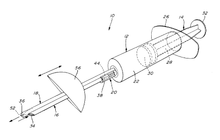
Referring first to Figs 1 and 2, there is
illustrated a wound irrigation device which is generally
designated by reference numeral 10 and comprises a
syringe 12, a plunger 14, inlet and outlet tubes 16,18
and a check valve 20. The syringe 12 has a hollow body
22 defining a chamber 24 adapted to contain a fluid
suitable for irrigating a wound (not shown), the body 22
being provided at one end with a finger flange 26. The
plunger 14 which is movable within the body 22 includes a
stem 28 provided at an inner end with a rubber head 30
and at an outer end with a thumb rest 32.
The inlet tube 16 is integral with the body 22
and is in fluid flow communication with the chamber 24
for filling the chamber with fluid in response to an
outward displacement of the plunger 14 relative to the
body 22. The outlet tube 18 is also integral with the
body 22 and is in fluid flow communication with the
chamber 24 for discharging the fluid from the chamber
onto the wound in response to an inward displacement of
the plunger 14 within the body 22. The inlet and outlet
tubes 16,18 extend side-by-side and have respective free
ends 34, 36 disposed adjacent one another. As shown, the
free end 36 of the outlet tube 18 extends beyond the free
end 34 of the inlet tube 16.
The check valve 20 is operative for selectively
allowing the fluid to flow through the inlet tube 16 and
into the chamber 24 in response the outward displacement
of the plunger 14, and for preventing the fluid from
flowing from the chamber 24 through the inlet tube 16 in
response to the inward displacement of the plunger 14.
- 4 -
CA 02244050 1998-07-28
As best shown in Fig. 2, the check valve 20 comprises a
valve body 38 defining a valve chamber 40 in fluid flow
communication with the fluid passageway 42 of inlet tube
16, and a cylindrical valve member 44 movable in the
valve chamber 40 between close and open positions to
selectively close and open the fluid passageway 42.
Planar elongated guide members 46 each provided with an
abutment 48 are arranged in the valve chamber 40 so that
the valve member 44 is movable along limited guided path,
the abutments 48 serving to arrest the valve member 44 in
the open position.
As also shown in Fig. 2, the outlet tube 18 has
a fluid passageway 50 with a first diameter and the free
end 36 of the outlet tube 18 defines a fluid discharge
orifice 52 having a second diameter smaller than the
first diameter, whereby to increase the pressure of the
fluid discharged from the orifice 52.
In operation, the inlet and outlet tubes 16,18
inserted are into a bulk container (not shown) of fluid
so that the free ends 34, 36 are immersed into the fluid,
the plunger 14 is displaced outwardly to draw fluid from
the bulk container through the inlet tube 16 and into the
chamber 24 of the syringe 12, with the valve member 44
moving to the open position, the tubes 16,18 are removed
from the bulk container and directed towards a wound to
be irrigated, and the plunger 14 is displaced inwardly
within the syringe body 22 to cause the fluid to flow
from the chamber 24 through the outlet tube 18 so as to
be discharged under pressure from the orifice 52 onto the
wound. As the plunger 14 is displaced inwardly within
the syringe body 22, the valve member 44 moves to the
close position, thereby preventing the fluid from flowing
from the chamber 24 through the inlet tube 16. The head
30 of the plunger 14 is provided with rubber sealing
- 5 -
CA 02244050 1998-07-28
rings 54 to ensure a fluid tight seal during displacement
of the plunger 14.
Since in use the free end 36 of the outlet tube
18 is positioned in close proximity to the wound, and in
order to present fluid splashes contaminated by the wound
form reaching the user during the inward displacement of
the plunger 14, a parabolic fluid splash arresting member
56 is mounted on the inlet and outlet tubes 16,18. The
member 56 has an opening (not shown) which is defined
therethrough and off-centered relative to the central
axis (not shown) of the member 56, the inlet and outlet
tubes 16,18 extending through the opening. The central
axis of the member 56 is inclined at an angle of about
30° relative to the longitudinal axes of the inlet and
outlet tubes 16,18 to provide a better protection. In
addition, the member 56 is slidably mounted on the inlet
and outlet tubes 16,18 for adjustable positioning
therealong.
Figure 3 illustrates a wound irrigation device
10' according to another preferred embodiment of the
invention. In the device 10', the syringe 12', tubes
16',18', valve 20' and syringe body 22' are the same as
the syringe 12, tubes 16,18, valve 20 and syringe body 22
of the device 10 shown in Figs 1 and 2, with the
exception that the inlet and outlet tubes 16,18' are
removably connected to the body 22' by means of a Luer-
lock type coupling system 58. Such a coupling system
comprises an adapter 60 having a finger-grip portion 62
and a threaded portion 64, and a threaded socket 66 which
is integral with the body 22' and into which the threaded
portion 64 of the adapter 60 is releasably engaged.
The wound irrigation devices 10 and 10' are
entirely made of polypropylene.
- 6 -