Note: Descriptions are shown in the official language in which they were submitted.
CA 02246698 1998-08-19
WO 97!31282 PCT/GB97/00490
CONFOCAL MICROSCOPE
The present invention relates to a confocal microscope and in
particular a confocal microscope which enables real-time imaging to be
s performed.
In approximately the past fifteen years confocai microscopes
have been developed and have been shown to provide advantages over
alternative microscopy systems such as greater spatial resolution and
depth discrimination. A schematic diagram of a known reflection confocal
to scanning microscope such as that described in Confocal Microscopy by
Tony Wilson, Academic Press (1990) is shown in Figure 1. The
microscope consists of a laser light source 1 from which laser light passes
to a lens 2 for generating a diffraction limited spot of light. The spot of
light
is reflected from an object 3 which is being scanned and the reflected light
is is extracted 4 and then passed to a photodetector 5. The reflected light
intensity is separately measured by the photodetector 5 for each scanned
point on the object 3. The signals generated by the photodetector 5 are
then used to intensity modulate a TV screen 6 which is scanned in
synchronism with the scanning spot of light. Known confocal microscope
2a systems such as the one described above have the disadvantage that very
bright light sources are required and this usually necessitates the use of
lasers. Also, as the microscope images by scanning a spot of light over
the object, real-time imaging could not easily be performed.
The optical sectioning and lateral resolution achieved with the
2s confocal microscope described above arises as a result of the illumination
and imaging systems being arranged whereby only light which has
originated from a specific position in the source plane is detected at the
equivalent position in the detector plane. In mathematical terms this is
described as the source and detector distributions being delta correlated
CA 02246698 2004-09-28
2
and with most known confocal microscopes is achieved by employing a single
point source and point detector.
In an alternative known confocal system which uses multiple point
sources and detectors, an extended light source is used together with a
spinning disc containing an array of pinholes usually arranged as interleaving
Archimedian spirals. In order to prevent cross-talk between neighbouring
pinholes, the pinholes are spaced far apart which results in an extremely low
light budget. In general, known confocal systems have the disadvantage that
the systems are designed for exact delta correlation between the source and
detector distributions which inherently limits the light budget possible with
the
systems.
The present invention seeks to overcome the disadvantages
described above with respect to known confocal microscopes whilst retaining
the advantages of optical sectioning and lateral resolution and seeks to
provide
a confocal microscope capable of performing real-time imaging with a
significantly improved light budget.
The present invention provides a confocal microscope having
means for directing light to a specimen to be imaged; at least one composite
image mask for encoding light incident on a plurality of regions of the
specimen
and for decoding light from a plurality of regions of the specimen
simultaneously thereby generating a confocal image of the specimen
superimposed on a non-confocal image; means for detecting decoded light
from the specimen and extraction means for separating the confocal image of
the specimen from the detected light. Ideally, means for separating the
confocal
image from the detected light is additionally provided.
Thus, with the present invention the requirement that the source
and detector masks are substantially delta correlated no longer applies, and
hence masks with greater light efficiency may be employed in comparison
with known confocal systems. Also, as the confocal image is formed
simultaneously with a plurality of regions, preferably all, of the
CA 02246698 1998-08-19
WO 97/31282 PCT/GB97/00490
3
confocal image, real-time confocal imaging of a specimen can be
performed.
Preferably, in order to maximise the available light budget,
the non-confocal image is substantially a conventional image. The non-
s confocal image though may include de-focused images and other imaging
artefacts.
Preferably, the confocal microscope is a reflection mode
microscope and a single mask is provided both for encoding light incident
an the specimen to be imaged and for decoding light from the specimen.
to Alternatively, the confocai microscope may be a transmission mode
microscope whereby two separate matched masks are provided.
fn a first embodiment the mask is in the form of at least one
spatial light modulator programmed to code and decode the incident and
emergent light. The spatial light modulator may be arranged to produce
is predetermined intensity modulation or polarisation modulation of incident
light. In an alternative embodiment the mask is in the form of at least one
rotating disk having a plurality of predetermined portions capable of varying
at least one characteristic of incident light to different extents. The
predetermined portions may be capable of varying the intensity, phase or
2o polarisation of incident light or any combination thereof.
The means for detecting the light from the specimen and for
separating out the confocal image may be in the form of an array of
photodetectors connected to a programmed computer. in an alternative,
where the polarisation of the incident light is encoded, the confocal image
2s may be extracted with a polarising beam splitter in combination with one or
more photodetector arrays or other camera device.
Preferably, the mask encodes the light incident on the
specimen using finite length binary time sequences. The combined
confocai and conventional image may then be obtained by time averaging
3o the detected image over the finite length of the sequence.
CA 02246698 1998-08-19
WO 97/31282 PCT/GB97/00490
4
Embodiments of the present invention will now be described
by way of example with reference to the accompanying drawings, in which:
Figure 1 is a schematic diagram of a known confocal
microscope;
s Figure 2 is a schematic diagram of a frst confocal
microscope in accordance with the present invention in transmission mode;
Figure 3 is a schematic diagram of a second confacal
microscope in accordance with the present invention in reflection mode;
Figure 4 is a diagram of one embodiment of an aperture
to mask used with confocal microscopes in accordance with the present
invention; and
Figure 5 is a diagram of a conventional microscope with a
confocal system in accordance with the present invention.
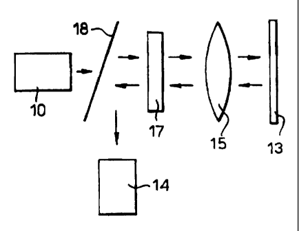
The confocal microscope shown in Figure 2 consists of a light
is source 10, a source mask 11 and a detector mask 12 either side of the
specimen to be imaged 13 and a CCD camera 14 beyond the detector
mask 12. The light source 10 illuminates the source mask 11 which is then
imaged onto the specimen by lens system 15 located between the source
mask 11 and the specimen 13. Lens system 16 located between the
2o specimen 13 and the detector mask 12 images the specimen onto the
detector mask 12. The camera 14 images the detector mask 12. Where
the confocal microscope is in reflection mode, as shown in Figure 3, the
source and detector masks 11,12 are replaced by a single aperture mask
17 and a beam splitter 18 positioned between the fight source 10 and the
2s aperture mask 17 is provided for directing the reflected light to the
camera
14. '
With reference to the aperture mask 17 of Figure 3, the mask
is encoded with a predetermined pattern so that each detector pixel acts as
a matched filter to its corresponding source pixel. In this way the desired
so correlation between the source and detector distributions may be achieved.
CA 02246698 1998-08-19
WO 97/31282 PCT/GB97100490
This in turn permits parallel processing of the whole image provided
suitable source pixel encoding and detector pixel decoding techniques are
employed. For example each source pixel may be modulated with a
unique time sequence and the same sequence used as a reference signal
s far matched filtering at the detector. Ideally the sequence presented to
each pixel should have zero cross-correlation with that presented to any
other pixel and an approximation to this is the use of independent random
binary sequences for each pixel. Sets of finite length sequences which
possess zero cross-correlation exist such as time-shifted complementary
to Golay sequences but the number of sequences in the set is limited to the
sequence length. As the likelihood of cross talk between distant pixels is
low in practice, rather than using a sequence length equal to the number of
pixels in the aperture mask a shorter sequence length may be used
provided that the requirement for zero cross-correlation is satisfied for
is neighbouring pixels. if intensity modulation is used a do shift must be
introduced to the sequences employed as the sequences include negative
numbers which cannot be reproduced optically. The result of this do shift is
that the image generated by the detector of the confocal microscope is a
composite of a conventional image and a confocai image. Post processing
Zo of the image enables the confocal image to be separated out electronically
in real-time. Where the image is being viewed directly by the eye,
however, the composite image may be viewed when the sequences are
presented faster than the eye is capable of responding.
One example of the type of aperture mask which may be
2s used is a spatial light modulator (SLM). An SLM consists of an array of
pixels in which each pixel is individually addressable. One of the
advantages of using the SLM is the fast frame rate which enables real-Time
imaging. One particular implementation of an SLM consists of a
ferroelectric liquid crystal device (FLCSLM) in which each pixel of the SLM
CA 02246698 1998-08-19
WO 97/31282 PC'1'/GB97/00490
6
acts as a birefringent retardation plate which can be switched in the plane
of the SLM between two orientations of its optical axes.
With the FLCSLM located between crossed polarising filters
aligned along the corresponding optical axes of one of the stable states of
s the FLCSLM, the FLCSLM can be used as an intensity modulator. With
this arrangement each individually addressable pixel of the FLCSLM
transmits light in one of the states of the FLCSLM and is opaque to light in
the other state of the FLCSLM and in this way the FLCSLM acts as a
programmable spatial intensity modulator. This though has the
io disadvantage that fight is lost due to attenuation in the opaque pixels.
In an alternative arrangement of the FLCSLM in which the
crossed polarising filters are replaced by a polarising beam spfitter and a
quarter-wave plate, the light incident on the FLCSLM is arranged to be
linearly polarised along the bisector of the principal axes of the two
is FLCSLM states whereby the FLCSLM functions as a polarisation
modulator. This results in fight which passes through the same pixel both
to and from the specimen experiencing a change in its polarisation
whereas light which, on reflection from the specimen, passes through a
pixel in a different state to the state of the pixel through which it passed
to
2o the specimen experiences no change in its polarisation. This in turn
results
in the polarising beam splitter rejecting light which passes through different
pixels on the way to and from the specimen. The camera positioned
behind the polarising beam splitter will therefore only register light which
passed through the same pixel to and from the specimen. The camera will
2s also register light which passed through a different pixel from the
specimen
which is in the same state as the pixel through which it passed to the
specimen. This will result in a conventional image being superimposed on
the confocal image. The conventional image, as mentioned earlier, may
be subtracted electronically from the combined image to form a pure
3o confocal image of the specimen. If, however, an image is formed using the
CA 02246698 1998-08-19
WO 97/31282 PCT/GB97100490
7
light rejected by the polarising beam splitter then the contrast of the
confocal part of the image is reversed. It is therefore possible to obtain the
confocal image in real-time merely by subtracting the images obtained at
both outputs of the polarising beam splitter. The polarisation approach has
s the advantage that less light is lost than in the arrangement where the
FLCSLM is arranged as an intensity modulator.
An alternative implementation of an SLM is a digital
micromirror device (DMD) which consists of a large array of very small
mirrors, each of which can be individually addressed to control deflection of
to an incident light beam. The DMD is particularly suited to use as an SLM in
reflection mode with the orientation of the individual mirrors being encoded
in a manner similar to that described above with respect to the FLCSLM.
Instead of an SLM the aperture mask may be in the form of a
spinning disc. The spinning disc may be impressed with the sequences or
is modulation codes photolithographically and an example of a suitable mask
for use in the confoca! microscope is shown in Figure 4. As it is necessary
for the conventional image to be subtracted from the confocal image, blank
sectors are provided on the disk to provide the conventional image. The
camera and the electronics are then synchronised with the disc rotation to
2o enable the subtraction to be performed. Although the spinning disk shown
in Figure 4 uses intensity modulation for the encoding in a further
alternative the spinning disk may be arranged to perform polarisation
modulation.
If the disc does not include the blank sectors described
2s above, the image produced is a combined confocal and conventional
' image with the confocal image appearing as a bright region superimposed
on the ordinary image. The absence of the blank sectors means that the
conventional image cannot be selectively extracted through appropriate
synchronisation as in the previous example. This image is particularly
3o useful for navigating around a specimen to identify a specific region of
CA 02246698 1998-08-19
WO 97/31282 PCT/GB97/00490
8
interest. In this case, the image is used in its combined form without
extraction of the confocal image. ,
Instead of the pattern of modulation codes shown in Figure 4,
the disc may be encoded with a regular, close packed pattern for example
s in the form of a checker-board or uniform lines of equal spacing. In this
case, if the disc is then illuminated with incoherent light a combined non-
confocaf and confocal image is obtained from which the confocal image
can be extracted in the manner described. Alternatively coherent
illumination may be employed when fluorescent imaging is being
io performed.
Instead of a straightforward subtraction of the two images,
the confocal image can be recalled using an alternative procedure in which
the image from a single camera consists of the conventional image to on
even lines and the combined conventional and confocal image to+I~ on odd
is lines. The image can be described as follows in which S has a value of +1
for odd lines and -1 for even lines:
1= l0+1o~1+S)l2
Multiplying image ! by S gives
IS=h/2+I~Sl2+IoS
This image contains a mixture of the confocai image and the confocal
image combined with the conventional image imposed on a carrier S.
Since the carrier S consists of positive and negative high spatial frequency
components to which the frequency components in the conventional image
2s are shifted, the confocal image may be easily extracted by low pass
filtering of the image IS. in practice this is performed by the use of fast '
Fourier transforms. In addition, once the confocal image has been
extracted it is also possible for the conventional image to be extracted. In
this way both confocal and conventional images may be generated
3o simultaneously.
CA 02246698 1998-08-19
WO 97/31282 PCT/GB97/00490
9
It will be apparent that in addition to the above described
. implementations of the aperture mask, further alternatives of encoding of
the aperture mask are envisaged. For example wavelength encoding or
. frequency modulation and demodulation of individual pixels or random time
s varying encoding of pixels with decoding by matched filtering through the
same mask may alternatively be employed. Also, although reference has
been made to a CCD camera it wilt be understood that alternative cameras
may be used with the confocal microscope described.
Although reference has been made primarily to the confocal
Io microscope in reflection mode and thus to an aperture mask, the extension
of this arrangement to the transmission mode is straightforward with the
aperture mask being replaced with matched source and detector masks.
With the confocai microscopes described above the image
quality and the light budget are independent of one another. The image
is quality is dependent on the sophistication and length of the code
sequences and the light budget is determined on the basis of the
modutation employed. The confocal microscope enables real-time imaging
to be performed and this includes all three-dimensional modes of
operation. Direct viewing of the composite image can be performed and as
2o shown in Figure 5 conventional microscopes may be easily converted to
generate confocal images as desired.
In Figure 5 a conventional microscope is shown comprising
an eye piece 20, a tube lens 21, a beam splitter 22, an objective lens 23
and a light source 24. The microscope usually operates in reflective mode
2s with the specimen 13 located beyond the objective lens 23. In order to
adapt the microscope to function as a confocal microscope, a confocal
attachment 25 is provided between the beam splitter 22 and the objective
lens 23. The confocai attachment 25 includes two lens systems 26,27
which are positioned one either side of an aperture mask 28 which is
CA 02246698 1998-08-19
WO 97/31282 PCT/GB97/00490
encoded in the same manner as described above sa that a combined
confocal and conventional image is obtained. .
Further advantages include the use of the confocal
microscope in fluorescent imaging without a laser light source and
s endoscopy using a fibre imaging bundle.