Note: Descriptions are shown in the official language in which they were submitted.
CA 02247128 1998-08-21
W O 97131241 PCTAJS97/02073
Vehicle Navigation and Route Guidance System
This invention relates to data processing control systems in
general and more particularly to motor vehicle navigation and route
5 guidance systems determining the destination address from a
telephone number. US class 364/444 or Int. class G06F 15/50.
BRIEF SUMMARY C)F THE INVENTION
Rackground of the Invention
There are fundamentally two different types of vehicle
navigational systems. The first system makes use of stored map
displays wherein the maps of a predetermined area are stored in the
invehicle computer and displayed to the vehicle operator or driver. The
maps, knowing the location where the vehicle started and where it is
15 to go, will highlight the d,irection and the driver will have to read the
display and follow the route. One such stored map display system
offered by General Motors on their 1994 Oldsmobile, uses Cilobal
Positioning System (GPS) satellites and advanced dead reckoning
techniques to determine a precise location. The driver enters details of
20 the desired destination into an on-board or invehicle, computer, in the
form of specific address, a road intersection, etc. The stored map is
displayed and the operator then pinpoints the desired destination. The
on-board computer then calculates the most efficient route. The on-
board computer then displays on a display unit, the distance to and the
25 direction of each turning maneuver in easy-to-read graphics and also
includes a voice prompt.
The second system, such as the Siemens Ali-Scout system,
requires that the driver key-in the destination address, in geodetic
3Q coordinates, into the invehicle computer. A compass means located in
the vehicle then gives a "compass" direction to the destination
address. Such a "compass" direction is shown in easy-to-read graphics
as an arrow on a display unit indicating the direction the driver should
go. Along the side of the road are several infrared beacon sites which
35 transmit data information to the properly equipped vehicle relative to
CA 02247128 1998-08-21
W 097131241 PCT~US97/02073
the preferred routing to the next adjacent beacon sites. From ail of the
data the invehicle computer receives, the invehicle computer selects
the desired beacon data information to the next beacon along the route
direction to the final destination and displays a graphic symbol for the
5 vehicle operator to follow and the distance to the desired destination.
There is no map to read, only a simple graphic symbol and a voice
prompt telling the vehicle operator where to turn and when to continue
in the same direction.
U.S. Patent 4,3~0,970, assigned to Siemens AG and issued on
September 21, 1982 to von Tomkewitsch and entitled "Method for
Traffic Determination in a Routing and Information System for
Individual Motor Vehicle Traffic" describes a method for traffic
management in a routing and information system for motor vehicle
15 traffic. The system has a network of stationary routing stations, each
located in the vicinity of the roadway, which transmit route
information and local information concerning its position to passing
vehicles. The route information which is transmitted is the preferred
routing to all beacons and zones adjacent to the beacon site. The
20 vehicle navigation system then selects a route from all the routes
transmitted by the beacon.
The trip destination address, via geodetic coordinates, is loaded
by the vehicle operator into an onboard device, a navigation processor,
25 in the vehicle and by dead reckoning techniques a distance and
direction graphic is displayed. The first routing station which the
vehicle passes transmits a message to the vehicle with route data to
all of the adjacent beacons one of which is the next routing station.
The vehicle receives the message and selects one of the recommended
3Q routes which will guide the vehicle towards its final destination. As it
executes the travel to the next beacon, it accumulates time and
distance traveled which it transmits to the second routing station
when it is interrogated by passing the second routing station. In this
manner, traffic management is updated in real time and the vehicles
3~ are always routed the "best way". Of course the best way may be the
GES.VON~ MUENCHEN 03 ; 8~ A 02247128 1998-08-21 23994a60- t+~l22 7~U 1~ 3a;# 2/ 3
Shortest way, the less tra~ellcd wa~r7 the cheapest way or any combi~ation
of these plu~ other ~iteria.
~ n J~r~nese publi~ation JP620869~, ~om S~l~it~rno Electric Ind. LTD,
d~tcd July 26, 1994, a controllcr in a motor vehicle o~e.at~s an automotive
telephoIle devicc through a modem alld a line cvml~-tion with a~ info~ ion
center is l~e~ ~u~ ll~d. W~en the line is connected, the tele~h~ne numbe~ of thedestinahon }nputted by an ~ t~ is tr~ it~ to the infic)trn~tion center. The
infor~nation center ~ansrnits a position coordinate cor~esp(~n~lin~ to the receivcd
tGlcphone number which is then rcLL~ J..;~te~ d stored in the cont~oller. Ttle
controller reads a m~p co~res~onding to the position coordinate fi~om a road mapmemory l:~y a memory device. A ~oad map is displayed on a display dev~ce in ~he
~est~nP~tion facility.
Sllmm~r of tlle ~n~v~n~ion
I~ both of the af~ wllioned systemsl the vehicle C~lJC-~L llaS had to enter
into the in~ehicle CO~ ltt;l, the geodetic coar~in~tes of the destination address.
These are la~tude aIld longitudG coor~in~t~. In e~ch case, the present systems
require each co~ ~Le to be at least a six di~t number, degrees, {~ Utt S and
seconds; thus, two six digit numb~rs must b~ entered. In order to get the
~oortlin~tes, the vehicle operator has to read a map or consult a look-up table and
by mean~ of a data keyboard7 key in the nllml~ors
In the Ali-Scout system, ~ese coor~ t~ would be inputted into the
navigation computer and until the ~ehiclc passed thc fi~st beacon site, the ~ehicle
display system indicates the corn~ lin~ to take. Once the vehicle passed the
first beacon7 ~e vehicle w~ll ~en receiYe information about the best route tc~ take
to the next adjace~t beacoIts and ~e c~ Lc.t knowing its present ~eodetic
location and the geodetic locatio~ of itS ~.stin~tion address, will select the best
-route in ~e ~i~ection of the destin~horl add~ess.
AMEI~O~D S~IEET
1- . a'
08/04 ' g8 WED 07: 57 [TX/RX No 9128]
GES.VON:EPA-MUENCHEN ~)3 ; ~ ~ ~A 0224~7l28l l998-l0~8-2l 23994560~ ~t4122 7~0 1~ 3a;# 3
3a.'-~ ",~
Othe~ kno~rl ve~iicle navig~ n systems are described in Lhe f~llowin~
doc~ nt~
In patent application WO-A-96/00373 the~e is desc~bed a vehiele
naviga~ion system which cornmllnic~tes with an external central processing
system .~ia a comrmmications rnedium ~ glo~l positioning ~ystem provides
CUl~lt posi~on data. Destination data is enteretl via keybo~d ~nd transmitted tothe ccnt~al co~ ul~r which calculates a route and ~ransmits the ro~te tc~ the
invehicle system
Patent application n~mb~r DE-A-43009~7 discloses a ~ehicle navigation
system usi~ a communications ~edium for ~ccessin~ a central map rl~t~h~e
~rom whiGh the most fzLvourable route is computed.
PatenL application nllmhcr DE-A-413~5~1 discloses a navig~tion system
~hich Iedefines the route o~the ~fehicle in response to the detail~ o~
vehicle position.
I~ patent application nlmber WO-A-9~/0~526 there is descnbed a system
wherein destina~ion data is transmiKed from the vehicle in ~e foml of a telephone
number Yia a beacon interface ~vhich is llsed by the central proccssing sy~tem to
identif~ the l?osition of the required destination.
One mcthod of introducing a ~n~ml~l coordinates of the rl~stin~tion address
req~ires l:he vehicle to study a map, a m~n~ l o~
- ~MENDc~ r
!
08/04 '98 WED 07:57 [TX/RX NO 9128]
CA 02247128 1998-08-21
W O 97/31241 PCT~US97/02073
some other data base means to determine the six digit word
coordinates of the destination address and then enter or key in each
word by means of a keyboard into the onboard memory. In the present
invention, the vehicle operator enters the phone number of the
5 destination by means of a phone-type number keyboard pad. The
onboard computer transmits this number to the central processing
station having a data base subsystem wherein the correlation of the
phone number, physical address and the geodetic coordinates such as
latitude and longitude are stored. The central processor then transmits
1Q the geodetic coordinates back to the onboard vehicle computer and the
destination address is automatically and correctly loaded into the
onboard memory.
In another embodiment, the onboard computer receives the
1~ present position from a GPS receiver and transmits both the present
position and the desired position to the central processing station by
means of a wireless communication means. The central processing
station computes a series of routing vectors which are transmitted
back to the onboard computer for display in a turn-by-turn manner the
20 route for the vehicle to take to the destination position.
In addition, the invention herein provides for the entry of data
input from various traffic functions to be put in the data base and such
information is transmitted to the various beacon sites in the system by
2~ the central processing unit to provide better data to the vehicles
concerning routing vectors.
It is therefore a principle advantage to have the operator load
the destination address into the invehicle system by the simple means
30 of dialing the telephone number of the destination and not requiring the
operator to refer to various maps or other data bases for such
destination coordinates.
It is another advantage to have the beacon sites be updated
35 with traffic functional information such as travel conditions and road
data, received from many sources and inputted into the central
....~
CA 02247l28 l998-08-2l
W O 97/31241 PCTrUS97/02073
processing unit and which is transmitted to the beacon sites from the
system central processing unit.
These and other advantages will become apparent from the
following drawings and detailed description.
Brief Description of the Drawings
In the drawings:
FIG. 1. is a system block diagram of the vehicle navigation and
route guidance system;
FIG. 2 is a detailed block diagram of the preferred embodiment
of the invention;
FIG. 3 is a driver interface device in the vehicle for transmitting
the destination phone number and accepting or rejecting a system
recommended route.;
FIG. 4 is a dashboard display in the vehicle to receive one form
of the information from the navigation unit including a preview of the
routing and alert by the system of an in-route change of routing;
FIG 5. is another embodiment of vehicle navigation and route
guidance system;
FIG. 6. is a detail of the data base of FIG. 5; and
FIG. 7 is a schematic of route vectors which are transmitted
over the wireless communication medium from a present position to a
destination position.
netailed Description of the Preferred Embodiment
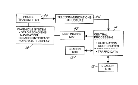
Referring to FIG. 1 by the characters of reference, there is
illustrated in block diagrammatic form a vehicle navigational and
routing system 10. As is known in the prior art, there are located along
the sides of the roadway, several beacon sites 12, or fixed guide
~' beacons 13, each placed strategically in the area. In an urban area,
such sites are within kilometers of each other and in the rural areas,
~ the beacon sites maybe spaced much, much farther apart.
It is the function of the beacon sites 12 to transmit information
received from a central processing means 14 including an information
CA 02247128 1998-08-21
W O 97/31241 PCTrUS97/02073
processor 15 and a data base 16 concerning the best route to take to
the adjacent beacon sites. The beacon sites 12 also receive
information from a vehicle including among other information abou~ the
elapsed travel time for links vehicle activity and other information to
assist in determining the "best" route from that particular beacon site
12 to each adjacent beacon site 12 and beyond.
In the prior art systems, such as the Ali-Scout System as
developed by Siemens Aktiengesellschaft, the vehicle operator has, in
10 his vehicle, an invehicle system 1 8 comprising a transmitter 20, a
receiver 22, an information processing unit 24 including a position
unit, a travel-time unit, a destination address processor and a memory
and a display means 26 having a data entry means such as a keyboard
28, an arrow indicator guidance visual display 30 and an audio or
15 voice messaging system 32. The Ali-Scout System is an infrared
communication system in that the medium for transmitting and receive
data from a beacon 12 to the invehicle system 18 is by means of
infrared waves.
In the prior art system, the vehicle operator had to input the
particular geodetic destination address coordinates found on a map or
some other data look-up means. These coordinates are typically the
latitude and longitude of the destination address which, of necessity,
~3re long digital words. The operator must accurately read these
numbers from his map and key them into the invehicle unit through the
alpha numeric keyboard.
In the preferred embodiment, the operator 34 by knowing the
phone number of his destination location does not have to read and
copy unfamiliar numbers into a keyboard. The typical phone number in
the United States is 7 digits long, not including the area code, and is
probably a familiar number. Therefore, the error of entering such a
number is much smaller. The invehicle system 18 transmits the phone
number to the central processor 14 and data base 16 as a destination
address request by conventional telecommunications methods such as
CA 02247128 1998-08-21
W O 97/31241 PCTrUS97/02073
a cellar telephone network or spread spectrum telephone network. The
central processor 14 and data base 16, has the street address and the
geodetic coordinates corresponding to the phone number stored in the
, data base 16 and coded in the proper form. This coded form is then
transmitted from the central processor 14 to the invehicle unit 18 as a
destination location address. Once the coordinates are located in the
invehicle unit 18, the system then prepares to receive from the next
beacon site 12 which it passes, the route information to the next
adjacent beacon sites 1 2.
Another feature of the preferred embodiment is the information
gathering capabilities of the central processor 1 4 and data base 16.
The information gathered is received from other sources such as
special events data 36 regarding such as sporting or cultural events,
15 traffic events data 38 regarding such as accidents and road repairs,
weather data 40, and other transient and incident data 42 which
would affect the movement of vehicles along the highways and
streets.
It is understood that the transmitters and receivers in the
invehicle unit 18, the central processor 14 and the beacon sites 12,
function to communicate and receive data between and among the
several units as the IVHS system requires. As will be shown, the
transmitter 20 can transmit data in the communication mode to the
central process 14 and later communicate in the infrared range to the
beacon sites 1 2.
Referring to FIG. 2, there is illustrated in block diagrammatic
form, the preferred embodiment of the system of FIG. 1. FIG. 2 is a
less detail block diagram which shows the invehicle system containing
the dead reckoning navigational system which is a basic element of
the system and the destination map 43 which is stored in the invehicle
system. The dead reckoning navigational system gives the operator 34
a compass bearing on the direction to go to the destination location. In
addition, the dead reckoning system maintains the proper compass
headings in the vehicle in order to accurately show the direction the
CA 02247l28 l998-08-2l
W O97/31241 PCT~US97/02073
vehicie must travel to reach its destination location when the vehicle is
in the autonomous mode of operation, that is before intercepting its
first beacon site 12 or when off the course derived from the beacon.
Also the invehicle system 18 has the beacon interface which was
5 previously described incorporating an infrared communication system.
The operator display means 26 was also previous described and will be
described in alternate embodiments with regard to FlGs. 3 and 4.
The new feature of the preferred embodiment is the phone
10 transmitter 44 which allows the destination location telephone number
to be transmitted through the telecommunications structure or
communications means 46 to the central processor 14. At the central
processor 14, the destination location or address telephone number is
converted to geodetic or map coordinates and transmitted by the
1 5 communications means 46 to the invehicle system 18. In the
alternative, the central processor 14 can also identify a specific street
address corresponding to the dialed telephone number. This
information can also be used for navigational purposes, or as additional
information for the operator. By means of the information provided by
20 the beacon site 12, the invehicle system 18 then operates to guide the
vehicle from its present position or location to its destination address
or location. In addition as previously indicated, the central processor
14 also transmits preferred routes to the beacon sites 12 based on its
knowledge of area-wide traffic conditions.
Once the geodetic coordinates from the central processor 14 are
inputted into the in vehicle system 18 the invehicle information
processing unit 24 takes the information from its memory as to its
present location, generates a direction indicator on the visual display
30 screen 30 directing the vehicle operator 34 as to the direction to go.
Once the vehicle is in position to communicate and does communicate
with the first beacon site 12, the information processing unit 24
selects the "best" route using the beacon site 12 supplied information.
The beacon site 12 transmits information on how to go to each
35 adjacent beacon site 12 and it is the function of the invehicle
information processing unit 24 is to select the appropriate direction
CA 02247128 1998-08-21
W O 97/31241 PCTAUS97/02073
information knowing its present location and the destination location.
All other information received from the beacon site 12 may not
utilized. The routing ;s either audibly 32 or visuslly displayed 30 or
both to the vehicle operator 34 and is updated each time the vehicle is
5 instructed to change course. The beacon site 12 receives information
from the invehicie information processing unit 24 as to the amount of
time and distance the car has traveled from a previous beacon so as to
update the central processor 14 and data base 16 for potential new
routing information. At no time does any part of the system, other
10 than the invehicle system 18 know where the vehicle is and where it is
0oing. ~his preserves the anonymity of each vehicle.
In FIG. 3, there is illustrated a keyboard 28 having a numeric
keypad 48 similar to that found on a telephone. This promotes ease of
15 data entry since most are familiar with a touch-tone phone keyboard.
Since this is a telephone, there are selection buttons 50 and 52 which
allow the operator 34 to indicate that the number being indexed into
the keypad 48 is either for telecommunications 50 or for IVHS
communications 52. As with most telephone keypads, the number
20 entered into the keypad 48 is displayed on a display panel 54 before it
transmitted. Once the correct number is displayed, the operator
confirms and activates the telephone. When the destination address
coordinates are returned to the invehicle system 18, the operator 34
indicates his or her acceptance by pushing the accept route button 56
25 and the vehicle is now able to function in the IVHS mode.
As soon as telecommunications such as a cellular phone is used,
total anonymity is no longer available. Location of a vehicle can be
established from the transmissions, but this is only implementable by
30 the central processor 14 having total access to the communications
network. As to the message content, the destination and routing could
be overheard, but the iocation and identification of the receiving
vehicle would not be available to a casual listener. For example, a
scanner will pick-up the data transmission, but not the location of the
35 receiving vehicle or person.
CA 02247128 1998-08-21
W O 97131241 PCT~US97/02073
One such method of communicating the route to the vehicle
operator is by a visual display device 58 as illustrated in FIG. 4. This is
intended to show a different mode of visual display to the operator 34;
i.e. after the invehicle information processing means 24 selects the
5 routing from the data received from the beacon 12, it can display the
routing in the following manner.
In this example, the visual display 30 shows the several street
names 60 that the vehicle will take to get to its destination location or
10 address. Next to each street name 60 is the compass direction 62 the
vehicle should proceed on that particular street 60. Both the route time
64 and the route miieage 66 is or maybe shown to the vehicle
operator 34.
Of key importance, is the data signal from the central processor
14 and data bank 16 to the beacon sites 12 that alerts the beacon
sites to a change in the route because of information gathered by the
system from the several beacons or other input means. Such
information may show heavy traffic congestion or a sudden repair
20 problem such as a water main break. This information is transmitted
by the central processor 14 and data base 16 to the site computer 68
at each beacon site 12 to alter the routes from each beacon site to the
adjacent beacon sites. The end result may be to redirect the vehicle
when it passes the next beacon site and thereby changing the display.
2~ The visual display device 58 may have a display 70 which alters the
operator 34 to a route change.
Still other embodiments of the system may provide information
in a package form to commercial vehicles such as trucks. In this case,
30 which is an example of a dedicated system, the anonymity is not an
issue. The beacons are either owned or operated by the trucking
company, or if there is a consortium of several companies, data from
each company can be encrypted.
The dispatching department of the a freight company can
access the central processor and data base with a routing for a given
CA 02247128 1998-08-21
W O 97131241 PCTrUS97/~2073
truck that is entering the area. This routing coincides with the delivery
points where the truck is to stop and discharge its load or a partial
load. As an example, ABC Cartage Company knows that its truck,
having a particular identification, will be arriving in the area with a load
5 of goods that is to be delivered to five different stops. The disp~tching
or similar department enters the destination address information of the
different stops into the central processor. When the beacon site picks
up the truck for the first time, it pulls the information of the five stops
from the data bank and transmits that information to the invehicle
10 information processing means 24 as a destination address message.
The invehicle system 18 processes the best route for the driver from
the normal beacon information. In the alternative, if the dispatcher
deems the order of the stops is important l~ecause of the vehicle
loading, the dispatcher develops the required destination address
15 message and adds any other information so that the driver follows the
best route.
There has thus been described an IVI IS system wherein the
geodetic coordinates of the destination location are transmitted over a
20 communications system to the invehicle system by means of standard
telephone communications. The telephone number of the destination
location is transmitted from the vehicle operator 34 to a central
processor 14 where it addresses a data base 16 to extract the
geodetic coordinates of the location having that phone number. The
25 central processor 14 then transmits those coordinates via the
communications medium to the invehicle information processing
means 24. Thus, the information processing means 24 develops the
direction that the vehicle is to take from its present location to the
destination with information being received from the several beacon
30 sites 12 which the vehicle passes.
,
Referring to FIG 5., there is illustrated another embodiment of
the vehicle navigational and routing system 10 as illustrated in FIG 1.
In this system, the invehicle system or computer 18 is essentially a
3~ "dumb" terminal in that there is very little processing capability other
than to direct the flow of information to and from system 18.
CA 02247128 1998-08-21
W O 97/31241 PCTrUS97/02~73
The system of FIG. 5 includes a transmitter 20, a receiver 22,
an information processing unit 24, a keyboard 28, an audio 32 and
visual 30 display unit, and a GPS receiver 72. The invehicle computer
18 is connected to wireless communications medium 74 to a central
processing means 14 having a receiver 76, information processor 15,
a transrnitter 78 and a map data base 79. Coupled to the data base 79
are severai inputs such as a cyclic and special event traffic data unit
36, a transients and incidents unit 40, a road attributes and conditions
10 unit 38, and other units 42 having information about vehicle travel
such as weather.
The operator 34 activates his invehicle system 18 by accessing
the wireless communications medium 74 and dialing up the central
15 processing means 14. Once the communication link is established, the
operator 34 dials in the telephone number of his destination position
75 or a short character description of the destination position. The
GPS receiver 72 outputs the geodetic coordinates of the present
position 77 of the invehicle system 18 to the information processing
20 means 24 creating a transmission message and if desired, a vehicle
identification description can be automatically or manually entered into
the message. Once the messa~e is complete, the central processor
means 14 receives the destination position telephone number or
description, the geodetic coordinates of the present position and the
25 vehicie identification if available.
In the map data base 79 is a look-up table correlating telephone
numbers with geodetic coordinates, and short character descriptions of
locations with geodetic coordinates. The size of the look-up table,
3Q determines the amount of information which can be addressed. The
central processor means 14 uses the telephone number or short
character description to determine the geodetic coordinates of the
destination position 75. Both the coordinates of the destination
position 75 and the present position 77 are supplied to the information
3~ processor 15 wherein a routing algorithm 80 generates routing vectors
82-87 along with distance (km) as illustrated in FIG. 7. The vectors
CA 02247128 1998-08-21
W O 97/31241 PCT~US97/~2073
t3
82-87 comprise direction and distance for the vehicle operator 34 to
follow, in a turn by turn mode, from his present position 77 to the
destination position . If a vehicle ID is present, the vehicle ID is
appended to the particular routing vectors for updating.
The transmitter 78 in the central processor means 14 transmits,
by the wireless medium 74 which has been held open by the invehicie
system 18, the calculated routing vectors 82-87 back to the invehicle
system. The receiver 22 in the invehicle system 18 receives the
10 calculated routing vectors 82-87 and stores them in the information
processor unit 24 in the invehicle system. Each vector 82-87 is
sequentially displayed, in a turn by turn display on the visual display
30 and each turn is audibly announced to the operator 34 through the
audio unit 32. As the invehicle system 18, which measures distance
15 and direction, becomes aware of the vehicle responding to the end of
the present routing vector 82-86, it causes the next sequential routing
vector 83-87 to be displayed. If the operator 34 ignores a routing
vector by not turning, or turns incorrectly at the proper distance, the
information processing unit 24 through the audio unit 32 audibly tells
20 the operator 34 that he/she has left the route and is capable of
displaying certain prestored error messages on the visual display 30.
If the vehicle ID is stored with the route request in the central
processing means 14, the operator 34 can dial-up the central
25 processing means and with the same information such as destination
position 75 and vehicle ID, but with the updated present GPS location,
which is now the present location, the central processing means can
interrogate the various updates to the map data base 79 and notify the
operator 34 of any change in the routing vectors. Depending upon the
30 complexity of the central processing means 14, a new set of routing
vectors from this new present location to the destination position 75
can be transmitted to the invehicle system 18 which will replace the
information in the information processing means 24 in the invehicle
system 18.
CA 02247l28 l998-08-2l
W O 97/31241 PCT~US97/02073
14
If the beacon sites 12 are available, the present position can be
determined from the beacons as described above.
There has thus been shown and described a second embodiment
5 wherein the system uses a wireiess communication medium 74
between an invehicle system 18 and a central processing means 14,
for the transmission of the destination location 75 in one direction
~transmittingJ and for generating and the transmission of routing
vectors 82 in the second direction ~receiving) that are generated by the
10 map data base and routing algorithm 80. The invehicle system 18 has
no map data base or any need to reinterpret the signals received from
the wireless communication medium 74. Map data is not
communicated along the wireless communication medium 74.
1~ Also if such an embodiment is used in a commercial system, the
vehicle operator or truck driver can communicate via the wireless
communications medium to the dispatcher for the next set of route
vectors from his present position, a stop, to the next destination
position, the next stop.