Note: Descriptions are shown in the official language in which they were submitted.
CA 02253048 1998-11-06
X257-35
B3Gk~7rOLrid Of t-hc ny nt-i nn
1. Fi_el_d Of th Tny nt-inn
The present invention relates to the papermaking
arts. More specifically, the present invention
relates to press fabrics for the press section of a
paper machine.
2 . D - ri b i on Of t-iZe Pri nr j~rf
During the papermaking process, a, cellulosic
fibrous web is formed by depositing a fibrous slurry,
that is, an aqueous dispersion of cellulose fibers,
onto a moving forming fabric in the forming section of
a paper machine. A large amount of water is drained
from the slurry through the forming fabric, leaving
the cellulosic fibrous web on the surface of the
forming fabric.
The newly formed cellulosic fibrous web proceeds
from the forming section to a press section, which
includes a series of press nips. The cellulosic
fibrous web passes through the press nips supported by
a press fabric, or, as is often the case, between two
such press fabrics. In the press nips, the cellulosic
- fibrous web is subjected to compressive forces which
squeeze water therefrom, and which adhere the
cellulosic fibers in the web to one another to turn
the cellulosic fibrous web into a paper sheet. The -
water is accepted by the press fabric or fabrics and,
ideally, does not return to the paper sheet.
The paper sheet finally proceeds to a dryer
section, which includes at least one series of
rotatable dryer drums or cylinders, which are
internally heated by steam. The newly formed paper
1
EH82'7300116US
CA 02253048 1998-11-06
sheet is directed in a serpentine path sequentially
around each in the series of drums by a dryer fabric,
which holds the paper sheet closely against the
surfaces of the drums. The heated drums reduce the
water content of the paper sheet to a desirable level
through evaporation.
It should be appreciated that the forming, press
and dryer fabrics all take the form of endless loops
on the paper machine and function in the manner of
conveyors. It should further be appreciated that
paper manufacture is a continuous process which
proceeds at considerable speeds. That is to say, the
fibrous slurry is continuously deposited onto the
forming fabric in the forming section, while a newly
manufactured paper sheet is continuously wound onto
rolls after it exits from the dryer section.
The present invention relates specifically to the
press fabrics used in the press section. Press
fabrics play a critical role during the paper
manufacturing process. One of their functions, as
implied above, is to support and to carry the paper
product being manufactured through the press nips.
Press fabrics also participate in the finishing
of the surface of the paper sheet. That is, press
fabrics are designed to have smooth surfaces and
uniformly resilient structures, so that, in the course
of passing through the press nips, a smooth, mark-free
surface is imparted to the paper.
Perhaps most importantly, the press fabrics
accept the large quantities of water extracted from
the wet paper in the press nip. In order to. fill this
function, there literally must be space, commonly
referred to as void volume, within the press fabric
for the water to go, and the fabric must have adequate
permeability to water for its entire useful life.
2
CA 02253048 1998-11-06
Finally, press fabrics must be able to prevent the
water accepted from the wet paper from returning to
and rewetting the paper upon exit from the press nip.
Contemporary press fabrics are produced in a wide
variety of styles designed to meet the requirements of
the paper machines on which they are installed-for the
paper grades being manufactured. Generally, they
comprise a woven base fabric into which has been
needled a batt of fine, nonwoven fibrous material.
The base fabrics may be woven from monofilament, plied
monofilament, multifilament or plied multifilament
yarns, and may be single-layered, mufti-layered or
laminated. The yarns are typically extruded from any
one of the synthetic polymeric resins, such as
polyamide and polyester resins, used for this purpose
by those of ordinary skill in the paper machine
clothing arts.
The woven base fabrics themselves take many
different forms. For example, they may be woven
endless, or flat woven and subsequently rendered into
endless form with a woven seam. Alternatively, they
may be produced by a process commonly known as
modified endless weaving, wherein the widthwise edges
of the base fabric are provided with seaming loops
using the machine-direction (MD) yarns thereof. In
this process, the MD yarns weave continuously back-
and-forth between the widthwise edges of the fabric,
at each edge turning back and forming a seaming loop.
A base fabric produced in this fashion is placed into
endless form during installation on a papermachine,
and for this reason is referred to as an on-machine-
seamable fabric. To place such a fabric into endless
form, the two widthwise edges are brought together,
the seaming loops at the two edges are interdigitated
with one another, and a seaming pin or pintle is
3
CA 02253048 1998-11-06
directed through the passage formed by the
interdigitated seaming loops.
Further, the woven base fabrics may be laminated
by placing one base fabric within the endless loop
formed by another, and by needling a staple fiber batt
through both base fabrics to join them to one another.
One or both woven base fabrics may be of the on-
machine-seamable type.
In any event, the woven base fabrics are in the
form of endless loops, or are seamable into such
forms, having a specific length, measured
longitudinally therearound, and a specific width,
measured transversely thereacross. Because paper
machine configurations vary widely, paper machine
clothing manufacturers are required to produce press
fabrics, and other paper machine clothing, to the
dimensions required to fit particular positions in the
paper machines of their customers. Needless to say,
this requirement makes it difficult to streamline the
manufacturing process, as each press fabric must
typically be made to order.
In response~to this need to produce press fabrics
in a variety of lengths and widths more quickly and
efficiently, press fabrics have been produced in
recent years using a spiral technique disclosed in
commonly assigned U.S. Patent No. 5,360,656 to Rexfelt
et al., the teachings of which are incorporated herein
by reference.
U.S. Patent No. 5,360,656 shows a press fabric
comprising a base fabric having one or more layers of
staple fiber material needled thereinto. The base
fabric comprises at least one layer composed of a
spirally wound strip of woven fabric having a width
which is smaller than the width of the base fabric.
The base fabric is endless in the longitudinal, or
4
CA 02253048 1998-11-06
machine, direction. Lengthwise threads of the
spirally wound strip make an angle with the
longitudinal direction of the press fabric. The strip
of woven fabric may be flat-woven on a loom which is
narrower than those typically used in the production
of paper machine clothing.
The base fabric comprises a plurality of spirally
wound and joined turns of the relatively narrow woven
fabric strip. The fabric strip is woven from
lengthwise (warp) and crosswise (filling) yarns.
Adjacent turns of the spirally wound fabric strip may
be abutted against one another, and the helically
continuous seam so produced may be closed by sewing,
stitching, melting or welding. Alternatively,
adjacent longitudinal edge portions of adjoining
spiral turns may be arranged overlappingly, so long as
the edges have a reduced thickness, so as not to give
rise to an increased thickness in the area of the
overlap. Further, the spacing between lengthwise
yarns may be increased at the edges of the strip, so
that, when adjoining spiral turns are arranged
overlappingly, there may be an unchanged spacing
between lengthwise threads in the area of the overlap.
In any case, a woven base fabric, taking the form
of an endless loop and. having an inner surface, a
longitudinal (machine) direction and a transverse
(cross-machine)) direction, is the result. The
lateral edges of the woven base fabric are then
trimmed to render them parallel to its longitudinal
(machine) direction. The angle between the machine
direction of the woven base fabric and the helically
continuous seam may be relatively small, that is,
typically less than 10°. By the same token, the
lengthwise (warp) yarns of the woven fabric strip make
the same relatively small angle with the longitudinal
5
CA 02253048 1998-11-06
(machine) direction of the woven base fabric.
Similarly, the crosswise (filling) yarns of the woven
fabric strip, being perpendicular to the lengthwise
(warp) yarns, make the same relatively small angle
with the transverse (cross-machine) direction of the
woven base fabric. In short, neither the lengthwise
(warp) nor the crosswise (filing) yarns of the woven
fabric strip align with the longitudinal (machine) or
transverse (cross-machine) directions of the woven
base fabric.
In the method shown in U.S. Patent No. 5,360,656,
the woven fabric strip is wound around two parallel
rolls to assemble the woven base fabric. It will. be
recognized that endless base fabrics in a variety of
widths and lengths may be provided by spirally winding
a relatively narrow piece of woven fabric strip around
the two parallel~rolls, the length of a particular
endless base fabric being determined by the length of
each spiral turn of the woven fabric strip, and the
width being determined by the number of spiral turns
of the woven fabric strip. The prior necessity of
weaving complete base fabrics of specified lengths and
widths to order may thereby be avoided. Instead, a
loom as,narrow as 20 inches (0.5 meters) could be used
to produce a woven fabric strip, but, for reasons of
practicality, a conventional textile loom having a
width of from 40 to 60 inches (1.0 to 1.5 meters) may
be preferred.
U.S. Patent No. 5,360,656 also shows a press
fabric comprising a base fabric having two layers,
each composed of a spirally wound strip of woven
fabric. Both layers take the form of an endless loop,
one being inside the endless loop formed by the other.
Preferably, the spirally wound strip of woven fabric
in one layer spirals in a direction opposite to that
6
CA 02253048 1998-11-06
of the strip of woven fabric in the other layer. That
is to say, more specifically, the spirally wound strip
in one layer defines a right-handed spiral, while that
in the other layer defines a left-handed spiral. In
such a two-layer, laminated base fabric, the
lengthwise (warp) yarns of the woven fabric strip in
each of the two layers make relatively small angles
with the longitudinal (machine) direction of the woven
base fabric, and the lengthwise (warp) yarns of the
woven fabric strip in one layer make an angle with the
lengthwise (warp) yarns of the woven fabric strip in
the other layer. Similarly, the crosswise (filling)
yarns of the.woven fabric strip in each of the two
layers make relatively small angles with the
transverse (cross-machine) direction of the woven base
fabric, and the crosswise (filling) yarns of the woven
fabric strip in one layer make an angle with the
crosswise (filling) yarns of the woven fabric strip in
the other layer. In short, neither the lengthwise
(warp) nor the crosswise (filling) yarns of the woven
fabric strip in either layer align with the
longitudinal (machine) or transverse (cross-machine)
directions of the base fabric. Further, neither the
lengthwise (warp) nor the crosswise (filling) yarns of
the woven fabric strip- in either layer align with
those of the other.
As a consequence, the base fabrics shown_in U.S.
Patent No. 5,360,656 have no defined machine- or
cross-machine-direction yarns. .Instead, the yarn
systems lie in directions at oblique angles to the
machine and cross-machine directions. A press fabric
having such a base fabric may be referred to as a
multi-axial press fabric. Whereas the standard press
fabrics of the prior art have three axes: one in the
machine direction (MD), one in the cross-machine
7
CA 02253048 1998-11-06
direction (CD), and one in the Z-direction, which is
through the thickness of the fabric, a multi-axial
press fabric has not only these three axes, but also
has at least two more axes defined by the directions
of the yarn systems in its spirally wound layer or
layers. Moreover, there are multiple flow paths in
the Z-direction of a multi-axial press fabric. As a
consequence, a multi-axial press fabric has at least
five axes. Because of its multi-axial structure, a
mufti-axial press fabric having more than one layer
exhibits superior resistance to nesting and/or to
collapse in response to compression in a press nip
during the papermaking process as compared to one
having base fabric layers whose yarn systems are
parallel to one another.
Because mufti-axial press fabrics of the
foregoing type have heretofore b-een produced only in
endless form, their use has been limited to press
sections having cantilevered press rolls and other
components, which permit an endless press fabric to be
installed from the side of the press section.
Nevertheless, their relative ease of manufacture and
superior resistance to compaction have contributed to
an increased interest and a growing need for a multi-
axial press fabric which may be seamed into endless
form during installation on a press section, thereby
making such press fabric available for use on paper
machines lacking cantilevered components. The present
invention, an on-machine-seamable mufti-axial press
fabric, has been developed to meet this need.
~"mmary of the Invention
Accordingly, the present invention is an on
machine-seamable mufti-axial press fabric for the
press section of a paper machine. The press fabric
8
_ CA 02253048 1998-11-06
comprises a base fabric having a first fabric ply and
a second fabric ply.
The base fabric is assembled from an endless base
fabric layer, which comprises a fabric strip having a
first lateral edge, a second lateral edge, a plurality
of lengthwise yarns and a plurality of crosswise
yarns. The fabric strip is spirally wound in a
plurality of contiguous turns wherein said first
lateral edge in a given turn of said first fabric
strip abuts said second lateral edge of an adjacent
turn. A helically continuous seam separating adjacent
turns of the fabric strip is thereby formed. This
seam is closed by abutting first and second lateral
edges to one another. The result is a base fabric
layer in the form of an endless loop having a machine
direction, a cross-machine direction, an inner surface
and an outer surface.
The endless base fabric layer is flattened to
produce the first and second fabric plies. The plies
are joined to one another at their two widthwise edges
at the folds produced when the endless base fabric
layer is flattened. At least one crosswise yarn in
each turn of the fabric strip is removed from the fold
at each widthwise edge of the flattened endless base
fabric layer. This provides unbound sections of the
lengthwise. yarns of the fabric strip. The unbound
sections are used as seaming loops to join the
widthwise edges of the flattened base fabric layer to
one another to form an endless loop.
Alternatively, instead of actually flattening the
endless base fabric layer to produce folds, any two
locations, separated by one half of the distance
around the endless base fabric layer, may be marked,
perhaps with a felt-tipped marker, with a band
extending in the cross-machine direction across the
9
CA 02253048 2000-02-29
endless base fabric layer, and at least one crosswise
yarn from each turn of the fabric strip removed from the
marked bands to provide the unbound sections of the
lengthwise yarns of the fabric strip.
At least one layer of staple fiber batt material is
needled into one of the first and second fabric plies and
through the other of the first and second fabric plies to
laminate the first and second fabric plies to one
another.
Therefore, in accordance with the present invention,
there is provided an on-machine-seamable mufti-axial
press fabric for the press section of a paper machine,
said press fabric comprising:
a base fabric, said base fabric having a first
fabric ply and a second fabric ply fashioned from an
endless base fabric layer, said endless base fabric layer
comprising a fabric strip having a first lateral edge, a
second lateral edge, a plurality of lengthwise yarns and
a plurality of crosswise yarns, said fabric strip being
spirally wound in a plurality of contiguous turns wherein
said first lateral edge in a given turn of said first
fabric strip abuts said second lateral edge of an
adjacent turn thereof, thereby forming a helically
continuous seam separating adjacent turns of said fabric
strip, said helically continuous seam being closed by
attaching abutting first and second lateral edges of said
fabric strip to one another, thereby providing said base
fabric layer in the form of an endless loop having a
machine direction, a cross-machine direction, an inner
surface and an outer surface, said endless base fabric
layer being flattened to produce said first fabric ply
and said second fabric ply having two widthwise edges,
CA 02253048 2000-02-29
said first fabric ply and said second fabric ply being
connected to one another at folds along said two
widthwise edges, at least one crosswise yarn in each of
said turns of said fabric strip being removed at each of
said folds at said two widthwise edges to provide unbound
sections of lengthwise yarns of said fabric strip at said
folds, said unbound sections being seaming loops for
joining said widthwise edges of said flattened base
fabric layer to one another to form an endless loop; and
at least one layer of staple fiber batt material
needled into one of said first and second fabric plies
and through to the other of said first and second fabric
plies to laminate said first and second fabric plies to
one another.
The present invention will now be described in more
complete detail with frequent reference being made to the
figures identified below.
Brief Description of the Drawings
Figure 1 is a schematic top plan view illustrating a
method for manufacturing the base fabric layer of the on-
machine-seamable mufti-axial press fabric of the present
invention;
Figure 2 is a top plan view of the finished base
fabric layer;
Figure 3 is a cross-sectional view taken as
indicated by line 3-3 in Figure 1;
Figure 4 is a top plan view of the base fabric layer
in a flattened condition;
Figure 5 is a perspective view of the base fabric
layer as shown in Figure 4;
l0a
CA 02253048 2000-02-29
Figure 6 is a schematic cross-sectional view of the
flattened base fabric layer taken as indicated by line 6-
6 in Figure 4;
Figure 7 is a plan view of a portion of the surface
of the base fabric layer;
Figure 8 is a plan view of the portion of the
surface of the base fabric layer shown in Figure 7
following the removal of some of its crosswise yarns;
lOb
CA 02253048 1998-11-06
Figure 9 is a schematic cross-sectional view,
analogous to that provided in Figure 6, following the
removal of crosswise yarns; and
Figures 10, 11 and 12 are schematic cross
sectional views of subsequent steps in the manufacture
of the on-machine-seamable multi-axial press fabric of
the present invention.
nPt ilPd Description of the Preferred Embod~me~t
Referring now to these figures, Figure 1 is a
schematic top plan view illustrating a method for
manufacturing the base fabric layer of the on-machine-
seamable mufti-axial press fabric of the present
invention. The method may be practiced using an
apparatus 10 comprising a first roll 12 and a second
roll 14, which are parallel to one another and which
may be rotated in the directions indicated by the
arrows. A woven fabric strip 16 is wound from a stock
roll 18 around the first roll 12 and the second roll
14 in a continuous spiral. It will be recognized that
it may be necessary to translate the stock roll 18 at
a suitable rate along second roll 14 (to the right in
Figure 1) as the fabric strip 16 is being wound around
the rolls 12,14.
The first roll l2.and the second roll 14 are
separated by a distance D, which is determined with
reference to the totallength, C, required for the
base fabric layer being manufactured, the total
length, C, being measured longitudinally (in the
machine direction) about the endless-loop form of the
layer, it being understood that the total length, C,
is twice the length of the on-machine-seamable multi-
axial press fabric being manufactured. Woven fabric
strip 16, having a width w, is spirally wound onto the
first and second rolls 12,14 in a plurality of turns
11 _
CA 02253048 1998-11-06
from stock roll 18, which may be translated along the
second roll 14 in the course of the winding.
Successive turns of the fabric strip 16 are abutted
against one another and are attached to one another
along helically continuous seam 20 by sewing,
stitching, melting or welding to produce base fabric
layer 22 as shown in Figure 2. When a sufficient
number of turns of the fabric strip 16 have been made
to produce layer 22 in the desired width W, that width
being measured transversely (in the cross-machine
direction) across the endless-loop form of the layer
22, the spiral winding is concluded. The base fabric
layer 22 so obtained has an inner surface, an outer
surface, a machine direction and a cross-machine
direction. Initially, the lateral edges of the base
fabric layer 22, it will be apparent, will not be
parallel to the machine direction thereof, and must be
trimmed along lines 24 to provide the layer 22 with
.the desired width W, and with two lateral edges
parallel to the machine direction of its endless-loop
form.
Fabric strip 16 may be woven from monofilament,
plied monofilament or multifilament yarns of a
synthetic polymeric resin, such as polyester or
polyamide, in the same manner as other fabrics used in
the papermaking industry are woven. After weaving, it
may be heat-set in a conventional manner_prior to
interim storage on stock roll 18. Fabric strip 16
includes lengthwise yarns and crosswise yarns,
wherein, for example, the lengthwise yarns may be
plied monofilament yarns while the crosswise yarns may
be monofilament yarns. Further, fabric strip 16 may
be of a single- or mufti-layer weave.
Alternatively, fabric strip 16 may be woven and
heat-set in a conventional manner, and fed directly to
12
CA 02253048 1998-11-06
apparatus 10 from a heat-set unit without interim
storage on a stock roll 18. It may also be possible
to eliminate heat-setting with the proper material
selection and product construction (weave, yarn sizes
and count s ) .
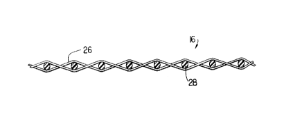
Figure 3 is a cross section of fabric strip 16
taken as indicated by line 3-3 in Figure 1. It
comprises lengthwise yarns 26 and crosswise yarns 28,
both of which are represented as monofilaments,
interwoven in a single-layer weave. More
specifically, a plain weave is shown, although, it
should be understood, the fabric strip 16 may be woven
according to any of the weave patterns commonly used
to weave paper machine clothing. Because the fabric
strip 16 is spirally wound to assemble base fabric
layer 22, lengthwise yarns 26 and crosswise yarns 28
do not align with the machine and cross-machine
directions, respectively, of the layer 22. Rather,
the lengthwise yarns 26 make a slight angle, 6, whose
magnitude is a measure of the pitch of the spiral
windings of the fabric strip 16, with respect to the
machine direction of the layer 22, as suggested by the
top plan view thereof shown in Figure 2. This angle,
as previously noted, is typically less than 10°.
Because the crosswise yarns 28 of the fabric strip 16
generally cross the lengthwise yarns 26 at a 90°
angle, the crosswise yarns 28 make the same slight
angle, 8, with respect to the cross-machine direction
of the layer 22.
Woven fabric strip 16 has a first lateral edge 30
and a second lateral edge 32 which together define the
width of the body of the woven fabric strip 16. As
the fabric strip 16 is being spirally wound onto the
first and second rolls 12, 14, the first lateral edge
13 _
CA 02253048 1998-11-06
30 of each turn is abutted against the second lateral
edge 32 of the immediately preceding turn.
Once the base fabric layer 22 has been assembled,
it may be heat-set prior to being removed from
apparatus 10. After removal, it is flattened as shown
in the plan view presented in Figure 4. This places
base fabric layer 22 into the form of a two-ply fabric
of length, L, which is equal to one half of the total
length, C, of the base fabric layer 22 as manufactured
on apparatus 10, and width, W. Seam 20 between
adjacent turns of woven fabric strip 16 slants in one
direction in the topmost of the two plies, and in the
opposite direction in the bottom ply, as suggested.by
the dashed lines in Figure 4. Flattened base fabric
layer 22 has two widthwise edges 36.
Figure 5 is a perspective view of the base fabric
layer 22 in a flattened condition. At the two
widthwise edges 36 of the flattened base fabric layer
22 are folds 38, which align with the transverse, or
cross-machine, direction thereof.
Figure 6 is a schematic cross-sectional view
taken as indicated by line 6-6 in Figure 4. In
accordance with the present invention, a plurality of
crosswise yarns 28 of fabric strip 16 and of segments
thereof are removed from adjacent the folds 38 to
produce a first fabric ply 40 and a second fabric ply
42 joined to one another at their widthwise edges 36
by unbound sections of lengthwise yarns 26. These
unbound sections of lengthwise yarns 26 ultimately
form seaming loops for use in joining the papermaker's
fabric to be produced from base fabric layer 22 into
endless form during installation on a paper machine.
The provision of the unbound sections of
lengthwise yarns 26 at the two widthwise edges 36 of
the flattened base fabric layer 22 is complicated by
14
- CA 02253048 1998-11-06
two factors. Firstly, because the fabric strip 16 has
a smaller width than the base fabric layer 22, its
crosswise yarns 28 do not extend for the full width of
the base fabric layer 22. Secondly, and more
importantly, because the fabric strip 16 is spirally
wound to produce base fabric layer 22, its crosswise
yarns do not lie in the cross-machine direction of the
base fabric layer 22 and therefore are not parallel to
the folds 38. Instead, as discussed above, the
crosswise yarns 28 make a slight angle, 0, typically
less than 10°, with respect to the cross-machine
direction of the base fabric layer 22. Accordingly,
in order to provide the unbound sections of lengthwise
yarns 26 at folds 38, crosswise yarns 28 must be
removed in a stepwise fashion from the folds 38 across
the width, W, of the base fabric layer 22.
For purposes of illustration, Figure 7 is a plan
view of a portion of the surface of base fabric layer
22 at a point on one of the folds 38 near the spirally
continuous seam 20 between two adjacent spiral turns
of fabric strip 16. Lengthwise yarns 26 and crosswise
yarns 28 are at, slight angles with respect to the
machine direction (MD) and cross-machine direction
(CD), respectively.
The fold 38, which is flattened during the
removal of the neighboring crosswise yarns 28, is
represented by a dashed line in Figure 7. In
practice, the base fabric layer 22 would be flattened,
as described above, and the folds 38 at its two
widthwise edges 36 marked in some manner, so that its
location would be clear when it was flattened. In
order to provide the required unbound sections of
lengthwise yarns 26 at the fold 38, it is necessary to
remove the crosswise yarns 28 from a region, defined
by dashed lines 46,48 equally separated from fold 38
CA 02253048 1998-11-06
on opposite sides thereof. Because crosswise yarns 28
are not parallel to fold 38 or dashed lines 46,48, it
is often necessary to remove only a portion of a given
crosswise yarn 28, such as in the. case with crosswise
yarn 50 in Figure 7, in order to clear the space
between dashed lines 46,48 of crosswise yarns 28.
Figure 8 is a plan view of the same portion of
the surface of base fabric layer 22 as is shown in
Figure 7 following the removal of the crosswise yarns
28 from the region centered about the fold 38.
Unbound sections 44 of lengthwise yarns 26 extend
between dashed lines 46,48 in the region of the fold
38. The portion of crosswise yarn 50 which extended
past dashed line 46 has been removed, as noted above.
Following the removal of the crosswise yarns 28
from the region centered about the fold 38, the base
fabric layer 22 is again flattened so that first
fabric ply 40 and second fabric ply 42 are joined to
one another by unbound sections 44 of lengthwise yarns
26. Figure 9 is a schematic cross-sectional view,
analogous to that provided in Figure 6, of one of the
two widthwise edges 36 of the flattened base fabric
layer 22.
Referring to Figure 10, a loop-forming cable 52
is next installed between first fabric ply 40 and
second fabric ply 42 and against unbound sections 44
of lengthwise yarns 26_. Stitches 54, for example,
may be made to connect first fabric ply 40 to second
fabric ply 42 adjacent to loop-forming cable 52 to
form seaming loops 56 from the unbound sections 44 of
the lengthwise yarns 26. Alternatively, first fabric
ply 40 may be connected to second fabric ply 42
adjacent to loop-forming cable 52 by any of the other
means used for such a purpose by those or ordinary
skill in the art.
16
CA 02253048 1998-11-06
Loop-forming cable 52 is then removed and the
seaming loops 56 formed in the foregoing manner at the
two widthwise edges 36 of the flattened base fabric
layer 22 are then interdigitated with one another in
a manner well-known to those of ordinary skill in the
art. As shown in Figure 11, a pintle 58 is directed
through the passage defined by the interdigitated
seaming loops 56 to join the two widthwise edges 36 of
the flattened base fabric layer 22 to one another,
thereby forming a two-ply base fabric 60 for an on-
machine-seamable multi-axial press fabric.
The two-ply base fabric 60 may, at this point,
again be heat-set. In any event, one or more layers
of staple fiber batt material 62 are needled into and
through the superimposed first fabric ply 40 and
second fabric ply 42 to join them to one another and
to complete the manufacture of on-machine-seamable
multi-axial press fabric 64. The staple fiber batt
material 62 is of a polymeric resin material, and
preferably is of a polyamide or polyester resin.
Finally, pintle 58 may be removed, and the staple
fiber batt material 62 cut in the vicinity of seaming
loops 56 to place press fabric 64 into open form for
shipment to a paper mill and for subsequent
installation there on a paper machine.
Modifications to the above would be obvious to
one of ordinary skill in the art, but would not bring
the invention so modified beyond the scope of the
appended claims.
17