Note: Descriptions are shown in the official language in which they were submitted.
CA 02254372 1998-11-17
-2-
Title: MOTORIZED WHEELCHAIR
FIELD OF THE INVENTION
This invention relates to the field of wheelchairs and
particularly to wheelchairs which are motorized and therefore self propelled.
Most particularly, this invention relates to those motorized wheelchairs which
are characterized by having drive wheels located generally under the centre
of the weight of the wheelchair occupant, or towards the front of the
wheelchair.
BACKGROUND OF THE INVENTION
Wheelchairs have been known and used extensively by
invalids for many years. More recently, improvements in electric motor and
battery design have led to more motorized wheelchair designs. Motorized
wheelchairs are ones which include a power source, such as a battery, and
drive motors powered by the power source, where the drive motors are
operatively connected to ground engaging drive wheels located on the
wheelchair.
A traditional wheelchair design includes larger rearwheels and
smaller swivelling front castor wheels. This design is appropriate for manual
wheelchairs for a number of reasons. Firstly, manual wheelchairs are
pushed by a person walking behind the wheelchair, by means of rearwardly
extending handles located at the top of the back seat rest of the wheelchair.
The large rear wheels add stability as the wheelchair is pushed. Having
smaller front swivelling castor wheels makes the wheelchair more
manoeuvrable when pushed from the rear. Lastly, having larger rear wheels
means that the wheel rims are accessible to the wheelchair occupant's
arms, permitting self propulsion by arm power.
However, the trend towards modern motorized wheelchairs
removes some of the advantages of the combination of large rearwheel and
CA 02254372 1998-11-17
-3-
smaller front castor wheel design. Most particularly, in a motorized
wheelchair, there is no need to have the wheelchair wheel rims accessible.
Lastly, having pivoting front wheels when the wheelchair is being driven by
rear wheels extends the turning radius of the wheelchair making it less
manoeuvrable.
Therefore, more recently, there have been proposed a number
of front wheel and midwheel drive wheelchair designs. In the new designs,
ground engaging drive wheels, powered by electric motors or the like, are
placed generally under the centre of the seat of the wheelchair to maximize
traction for the drive wheels. Rear pivoting castor wheels are provided for
stability.
However, there is a problem with such midwheel designs. It
is not uncommon to need to stop a motorized wheelchair suddenly. This
may occur by reason of a loss of power, or, by reason of a need for
preventing an accident. This sudden stop creates a forward moment about
the ground engaging midwheels, and in the absence of countermeasures
would cause the wheelchair to tip forward. Therefore, midwheel design
wheelchairs require forwardly extending anti-tip devices which may take the
form of a bar for example, having at its free end an anti-tip wheel.
Developing a proper anti-tip device is difficult. If the anti-tip
wheel is raised above the riding surface, the occupant of the wheelchair
tends to feel the wheelchair rocking forwardly when suddenly stopping
during deceleration as the rear castor wheel lifts off the ground and the
front
anti-tipping wheel contacts the ground. Consequently, some manufacturers
have provided anti-tip wheels which ride in contact with the ground engaging
surface, or just above the ground engaging surface to minimize the rocking
action during deceleration. This is problematic however because the ground
engaging anti-tip wheels make it very difficult to manoeuvre the wheelchair
over uneven ground such as curbs and sidewalks. However, raising the
anti-tip device above the riding surface creates the unwanted rocking
motion.
CA 02254372 1998-11-17
-4-
SUMMARY OF THE INVENTION
What is desired is an anti-tip structure for a midwheel drive
wheelchair which prevents unwanted rocking motion while at the same time
rides sufficiently high above the riding surface so as to reduce problems on
uneven surfaces. Most preferably, such a wheelchair would provide such
an anti-tip mechanism in association with power driven ground engaging
midwheel drive wheels. Therefore, according to one aspect of the present
invention there is provided a motorized wheelchair comprising:
a frame having a front, a back and opposed sides, said frame
comprising an upper seat mounting portion and at least one rear ground
engaging castor wheel;
a pair of pivoting lower carriage portions, said pivoting lower
carriage portions each being pivotally mounted to said frame by a respective
pivot located towards the front of said frame;
a biasing element extending between each of said carriage
portions and said frame remote from said pivotal mountings;
a ground engaging drive wheel on each of said pivoting
carriage portions;
a motor means mounted to each of said pivoting carriage
portions and operatively connected to said ground engaging drive wheels for
driving each of said ground engaging drive wheels; and
anti-tip means, mounted to each said pivoting carriage portions
and extending forwardly therefrom, said anti-tip means comprising an anti-tip
arm having an anti-tip wheel proximate to a free end.
BRIEF DESCRIPTION OF THE DRAWINGS
Reference will now be made to the following drawings which
depict a preferred or preferred embodiments of the invention, by way of
example only, and in which:
Figure 1 is an isometric view of a wheelchair base according
to the present invention;
CA 02254372 1998-11-17
-5-
Figure 2 is a side view of the wheelchair base of Figure 1
along lines 2-2 of Figure 1 according to the present invention;
Figure 3 is a side view of the wheelchair according to Figure
2, during deceleration;
Figure 4 is a close up side view of a front anti-tip wheel
according to a further aspect of the present invention; and
Figure 5 is a close up side view of a front anti-tip mechanism
according to a further aspect of the present invention; and
Figure 6 is a view of a complete wheelchair assembly
according to the present invention.
DETAILED DESCRIPTION OF THE PREFERRED EMBODIMENTS
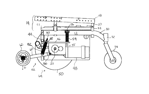
The wheelchair base 10 according to the present invention is
shown in Figure 1. The wheelchair base 10 includes a base frame 12 which
includes a seat mounting portion 14 and a pivoting drive and carriage portion
16. The seat mounting portion 14 includes a seat frame 18, which attaches
to frame 12. U-shaped attachment ears 20 extend down from the seat
frame 18, and are attached to short posts 22 extending up from the frame
12. Extending across the front of frame 12 is a rectangular tube 21. A
similar tube extends across the back. The battery box 19 shown in ghost
outline and lid 23 are supported in the base frame 12. The battery box 19
is sized and shaped to house conventional wheelchair batteries, and is
preferably made from moulded plastic. Extending rearwardly from the frame
element 12 is a curved mounting arm 30 having a castor mount 32 for rear
castor wheel 34.
Also shown in Figure 1 is the pivoting drive and carriage
portion 16. As will be appreciated by the following description, in the most
preferred embodiment each side of the wheelchair 10 includes its own main
drive wheel, each of which is independently driven and suspended. Thus,
while reference is made herein to carriage portion 16, it will be appreciated
that there are identical carriage portions 16 on each side of the wheelchair.
CA 02254372 1998-11-17
-6-
The wheelchair frame 12 includes a front indicated generally at 40, and a
rear indicated generally at 42. As shown in Figure 2, the carriage portions
16 are attached to the base frame 12 by a pivoted connection, shown at 44.
The carriage portions 16 include a frame element 46, a motor 48, a ground
engaging drive wheel 50 and an anti-tip mechanism indicated generally at
52. It will be appreciated that there are two ground engaging drive wheels
50, one of each of said drive wheels 50 being mounted on each side of the
wheelchair 10.
As can be seen in Figure 1, the pivot 44 is mounted towards
the front 40 of the frame. In Figure 2, remote from the pivot 44 is provided
a main suspension spring at 54 extending between the carriage portion 16
and base frame 12.
It can be now appreciated that the preferred location for the
rotational axis (or axle 51 ) of the ground engaging drive wheel 50 is
generally in front of the centre of the seat frame 14. To maximize the
ground engaging contact, it would be preferable to optimize the location of
the ground engaging drive wheels exactly under a centre of gravity of the
person occupying a seat (not shown) mounted on said seat frame 14.
However, for general stability reasons, it is preferred to mount the ground
engaging drive wheels slightly forward of the exact centre of gravity. This
permits the ground engaging drive wheels to carry a substantial portion of
the weight of the occupant of the wheelchair (improving traction), without
making the wheelchair overly tippy by being balanced on a single point. In
other words, it is most preferred to have between 10% to 20% of the load
carried by the rear castor wheel.
It can now be appreciated, that by mounting the carriage
portion 16 by a pivot point 44 located forwardly, and providing a pair of
ground engaging drive wheels 50 rearwardly of this position, that the weight
of a passenger on the wheelchair, will tend to rotate the rear of carriage
portion 16 upwardly against spring 54. Therefore, according to the present
invention the preferred configuration is to have a forwardly oriented pivot
CA 02254372 1998-11-17
-7-
point 44, a generally centrally located pair of ground engaging driving
wheels 50, slightly forward of centre for stability reasons, and a spring or
biasing means 54 remote from the pivot point 44, extending between the
carriage portion 16 and the base frame 12. This configuration adds comfort
to the occupant, since their weight is essentially carried on the spring 54,
which provides a smooth ride with independent suspension.
As shown in Figure 2 the biasing element 54 is provided with
a threaded rod 55 and an adjustment nut 56 at a top end. In this way, the
biasing element can be preloaded or compressed to provide a certain
predetermined spring force. The greater the preloading, the less the
compression when a person sits on the wheelchair. Thus, very light
occupants need less preloading, whereas very heavy (over 250 Ibs.) may
need more preloading of the spring. Adequate results have been achieved
with spring constant that permits factory setting of the preload compression
so as to permit a range of weights up to about 250 Ibs. Above this weight,
it may be necessary to alter the spring constant and substitute a sturdier
spring.
Referring now to the anti-tip mechanism 52, it is characterized
by a forwardly extending arm 60 having an anti-tip wheel 62. As shown in
Figure 2, the anti-tip wheel 62 is typically above the ground surface 64 by a
distance D when a person is seated in the wheelchair. To improve the
manoeuvrability of the present motorized wheelchair, it is preferred to make
the distance D sufficiently large that surface disconformities such as cracks,
bumps, and other smaller obstacles, and the shock therefrom, are not
transmitted to the wheelchair occupant during motorized driving. Most
preferably, distance D is adjustable as described below but typically will be
in the range of 1 inch to 2'/2 inches. However, according to the present
invention, there is also provided a smooth transition (i.e. without rocking)
upon sudden braking or the like. It can now be understood how the present
invention provides a smooth transition upon braking while simultaneously
preventing tipping.
CA 02254372 1998-11-17
-$_
Referring now to Figure 3, when an occupant first sits in the
present invention, the weight is generally taken up by the suspension spring
or biasing means 54. In the event of a sudden deceleration, the momentum
effect of the passenger will be to create additional force downwardly on the
wheelchair at the front edge. This will compress the biasing element 54
more, and cause the front 40 of the wheelchair to subside, essentially,
tilting
forwardly slightly.
Simultaneously with this, if the motor has locked with the drive
wheel, the forward momentum of the wheelchair and occupant will continue
to rotate the ground engaging wheel 50. Thus, the rear motor will be urged
by the forward momentum of the wheelchair to rise upwardly as the ground
engaging wheels are torqued to a stop. This again compresses the spring
54, and further lowers the front edge of the wheelchair. This is shown in
Figure 3, where the normal riding position is shown in said outline, and the
full braking position is shown in dotted outline. In this drawing D is broken
down into two components D, and D2. D, represents the amount the seat
lowers during stopping, by reason of the motor rotating against biaser 54.
D2 represents the amount the anti-tip wheel must rotate to contact the
ground, shown in dotted outline as 64'. It will be appreciated that the actual
ground level does not change, but for ease of illustration, this Figure
separates out the distances by seat subsidence and rotation of the anti-tip
means downwardly.
As can be seen in the drawings, the anti-tipping device 52 is
a forward extension of the pivoting carriage portion 16. The movement of
the end of the anti-tipping device 60 during sudden stopping, and in
particular the anti-tipping wheel 62 can now be understood. The rotation of
the drive wheel 50 is defined by a first radius, shown as R1 about the pivot
point 44. Rotation of the anti-tipping wheel 62 is defined by a second radius
R2 from the pivot point 44. It will be appreciated that if the anti-tip wheel
is
located directly under the pivot point 44, rotation will move the anti-tip
wheel
62 tangentially backwardly, but not downwardly. It is preferred to orient the
CA 02254372 1998-11-17
_g_
anti-tip wheel 62 significantly forwardly of the pivot point 44, so that
rotation
about the pivot point 44 includes a significant downward component to the
movement. A restraint on the forward location of the anti-tip wheel is overall
wheelchair length which is preferred to be as short as possible. Good
results are achieved when the anti-tip wheel 62 is centred between 8 to 14
inches ahead of the pivot point 44 and most preferably about 10 to 12
inches. On a sudden stop, this forward positioning results in the pivoting
downwardly of the anti-tipping device 60. This downwardly pivoting, quickly
moves the anti-tipping device into contact with the ground before any
rocking is detected by the rider of the wheelchair. In other words, the rear
castor wheel does not leave the ground during this deceleration and there
is no rocking. Most preferably therefore, the present invention provides a
combination of spring biasing, and pivot arm rotation to cause the anti-tip
wheel to contact the ground prior to the rear castor wheel leaving the
ground.
It will be appreciated that to achieve this result requires careful
tuning of the spring 54, with the radius R1 and R2. For example, if R2 is
twice R1 in length, then it will displace, along a circular arc, an amount
twice
the length of the displacement of axis 51 along R1. The amount of
displacement is a function of the weight or force imposed during
deceleration, together with the spring constant K of the spring 54.
Essentially what is desired therefore is for the anti-tip wheel 62 to contact
the ground prior to any tipping which would lift rear castor wheel 43 off of
the
ground. Of course, once braking is completed, the forces will be spent and
the anti-tip wheel will rise up off the ground to the normal running position.
Returning to Figure 2, it will be noted that there is an additional
pivot point 80, and a further suspension spring 82, extending between the
anti-tipping arm 60 and the pivoting carriage 16. This is one way of
providing a means to permit the anti-tip wheel to rise up over obstacles
without lifting the driving wheels off the ground. Also, similar to biasing
element 54, a threaded rod 83 is provided with suspension spring 82, which
CA 02254372 1998-11-17
-10-
is threaded through motor arm 46 which rotates about pivot point 44.
Rotating a nut 85 on the threaded rod 83 has the effect of compressing or
loosening spring 82, which in turn has the effect of raising and lowering anti-
tip wheel 62, thereby changing the distance D. Individual passengers may
have individual preferences for an acceptable D required to limit rocking as
described above. Depending upon the weight of the occupant, the distance
D will be higher (less weight) or lower (more weight). This adjustment
permits the height D to be preset for the end user when the end user is in
the wheelchair.
Figure 4 shows a further aspect of the present invention
relating to the anti-tip structure 52. In this Figure the wheel 62 is shown
with
an axle 100, which is housed in a slot 102. The slot includes a notch at 104,
and is formed in plate either attached to or made integral with arm 60.
Figure 4 also shows a strike line 110 and a spring 112 which can be now be
explained.
Even with the pivot arm 60, there can be difFicultly in getting
the anti-tip wheels above obstacles. By attaching the arm 60 to the motor
mount 45, the present invention teaches a greater normal D than is
presented in the prior art. However, overcoming higher obstacles, without
losing secure riding and stopping (i.e. traction) remains an issue.
The spring 112 biases the axle 100 into a normal running
position within notch 104. One end of the spring 112 is attached to axle
100, and the other end is fixed to the plate at 114. Notch 104 is sized and
shaped to retain the axle 100 within the notch for any force generated
behind strike line 110, such as F, as shown. This direction of force would
be generated during stopping motion for example.
On the other hand, for any force generated ahead of the strike
line 110, such as F2, the slot 100 is sized to permit the axle 100 to be
unseated allowing the axle to ride up the slot to a second, raised position
shown as 100'. In this position the spring is compressed as shown at 112'.
An example of an F2 force would be the reaction force caused by bumping
CA 02254372 1998-11-17
-11-
into a curb or the like. Thus it can be seen that the present invention
contemplates a slot, which has a height H, which adds to the height of an
obstacle surmountable by the present invention anti-tipper 52.
Figure 5 shows a further aspect of the present invention to
permit the anti-tip wheel 62 to rise over obstacles. This aspect relates to
making main spring 54' double acting as described below. As shown, the
motor pivot arm 46 includes a pair of right angle elbows 150 and 151 an the
end remote from pivot 44. Thus, rather than intersecting the spring 54' at
the bottom edge 152, the end 154 of the motor pivot arm 46 intersects the
spring 54' at point 156, about one third of the way up from the bottom 154.
In addition, rather than the front anti-tip pivot arm 60 being sprung to the
motor pivot arm 46, it is attached by a fixed link 160. The link 160 includes
a threaded portion 162 and adjustment nuts 164, 165, so that the height D
may be adjusted by increasing or shortening the length of the link 160,
similar to what was previously described. While the spring 54' is shown as
being the same above and below intersection point 156, the present
invention comprehends making the spring 54' out of two separate spring
portions 170, 172, which can be adjusted to react differently, to develop the
desired movement of the anti-tip wheel 62. One way this can be adjusted,
is to provide different spring constants. Thus, the portion 170 can be made
stiffer, to provide a smooth suspension ride, and the portion 172 can be
made more flexible, to permit the anti-tip wheel 62 to ride over obstacles.
Each section is preloaded by separate adjustment nuts 171, 173 as shown,
so even if the same spring 54' is used, each could be separately preloaded
to provide different displacements under the same force.
As can now be understood, double acting main spring 54' can
support the weight of a user under compression, during ordinary use, and,
extend to permit the anti-tipping wheel to raise up, when the anti-tip wheel
encounters an obstacle in front of the wheelchair.
Figure 6 shows a fully assembled wheelchair according to the
present invention. As shown there is a seat back 200 and a seat cushion
CA 02254372 1998-11-17
-12-
202 which are attached to the seat frame 18. Also shown are arms 204 and
206 with arm pads 208 and 210 respectively. Also shown is a control box
212, with a joystick 214 attached by means of a mount 216.
It can now be appreciated that the attachment between the
seat frame 18 and the main frame 12 facilitates the ease of use of the
wheelchair 10. Specifically, the front U-shaped attachment ears 20 latch
into the front posts 22, white the rear attachment ears 20 are pivoted into
rear attachment posts 22. In this way, a latch (not shown) can be released
to allow the seat frame to be pivoted rearwardly about the rear ear/post
attachment. This provides easy access to the battery box 19 previously
described. Those skilled in the art will realize that changing the batteries
is
required from time to time and this easy access facilitates this.
Below the seat frame is cowl 220 which is sized and shaped
to cover the main wheels 50, and extend out towards the rear castor wheels
34. A forward U-shaped frame element 222 is provided, from which is
suspended a foot tray 224. A bearing pad (not shown) is carried by the foot
tray. Alternately, the wheelchair 10 could be provided with individual foot
stirrups of a known configuration.
The present invention comprehends mounting the anti-tip
mechanism to the pivoting lower carriage portions, to more quickly engage
the anti-tip mechanism with the ground during sudden stopping. This
permits the anti-tip wheel to be carried higher above the ground than if it
were connected to the frame. In addition, three aspects of the invention
comprehend additional mechanisms for improving the ability of the anti-tip
wheels to surmount obstacles during normal use, without substantially
detracting from the performance of the anti-tip wheels during sudden
stopping. These additional aspects include mounting the anti-tip wheels on
pivoting anti-tip arms, which are spring-loaded to the pivoting lower
carriage;
providing a moveable axle means for the anti-tip wheel on the anti-tip arm;
and providing a double acting main suspension spring for each carriage
portion, which permits the carriage portion to pivot in both directions
relative
CA 02254372 1998-11-17
-13-
to the pivot point, thereby allowing the anti-tip wheel to rise over
obstacles,
as well as pivot down into contact with the ground during stopping.
It will be appreciated by those skilled in the art that various
modifications and alterations can be made to the invention without departing
from the broad scope of the present invention. For example, while reference
has been made to a first biasing element 54 in the form of a coil spring,
otherforms ofdeformable supports, such as pneumatic pistons, rubber pads
and the like might also be suitable, provided that an appropriate amount of
deformation occurs during deceleration to permit anti-tipping wheel to
engage the ground prior to rear castor wheel being disengaged from the
ground.