Note: Descriptions are shown in the official language in which they were submitted.
CA 022~839 1998-11-19
WO 98/01760 PCT/US97111718
AUTOMATED SAMPLE PROCESSING SYSTEM
BACKGROUND
The present invention relates generally to systems for the automation of
laboratory tests, and particularly testing of ~.ologi~ specimens.
Labo~dlo~ testing has changed and improved ,emarkably over the past
70 years. Initially, tests or assays were performed manually, and generally utilized large
quantities of serum, blood, or other biological fluids. However, as mechanical
technology developed in the industrial workplace, similar technology was introduced into
the clinical labordlory. With the introduction of new technology, methodologies were
10 also improved resulting in improved quality of the results produced by the individual
instruments, and a decrease in the amount of specimen required to perform each test.
Instruments have been developed to increase the erriciancy of testing
procedures by reducing tumaround time and decreasin9 the volumes necess~ry to
perform various assays. Exe",plaly of such instnuments are the SynchronTM line of
15 a- lomated analyzers available from Beckman Instruments of Fullerton, Califomia. Such
instruments are c~p~hlQ of aulu,),dlically analyzing a large number of blood specimens
and a large number of analytes, providing reliable, accurate, and fast analysis of
specimens.
There remains room for improvement in the operations of clinical
laboralories, in spite of the advances that have been made. For example, significant
labor is still required for sample preparation. Sample preparation can include the sorting
CA 022~839 1998-11-19
WO 98/01760 PCT/US97/11718
of specimens for processing, centrifugation, and removal of the caps of containers
containing the specimens. Centrifugation requires loading multiple specimen containers,
which are typically test tubes, into centrifuge buclcetc, balancing the weight of the
buckets so the centrifuge is balanced, loading the buckets into the centrifuge, closing
5 the centrifuge lid, centrifuging, opening the lid, removing the buckets, and then removing
the test tubes from the buckets. All these operations are labor intensive, increasing the
cost of labordlory analysis. Moreover, these labor intensive steps can lead to operator
error. Also, human involvement always involves the risk of contamination of specimens
by the operator, and exposure of the operator to dangerous biological subslances.
There have been attempts to improve auto",alion include the use of
conveyor systems for conveying specimens to analyzers, such as those described in
U.S. Patent Nos. 5,178,834 and 5,209,903. A difficulty with using conveyor systems is
that they generaliy are part of a total integrated system, which system includes special
analyzers and other handling e~uipment. Thus a clinical laboratory that wishes to switch
15 to a conveyor system may need to replace its entire existing system, with attendant high
capital investment and significant training expense for the operators.
Another cG",r.,on problem in clinical laboratory systems is how to deal
with "STAT" speci",ens. These are specimens that need immediate attention. For
example, specimens from patients in the emergency room often require "STAT" analysis
20 so attending physicians can determine the cause of the medical emergency. Present
clinical systems currently depend on operator intervention to interrupt the normal flow of
work to be certain that the STAT samples get immediate attention. However, in the
hustle and bustle of a clinical laboralory these STAT samples and specimens do not
always get the immediate allention they need.
Laboratory centrifuges of the prior art typically have a high-speed motor-
driven spindle, a plurality of holders for test-tubes, test-tube racks and/or vials being
provided at respective angularly spaced slalions of a head assembly of the spindle, the
head assembly being located within a tub-shaped cavity and surrounded by a safety
ring, the centrifuge also having a safety-latched door for covering the cavity during
operation of the spindle. The spindle is driven at a selected speed which can be as high
as from about 3600 RPM up to about 100,000 RPM.
A number of challenges are ~csoc~t~d with aulol"alion of centrifugation.
For example:
CA 022~839 1998-11-19
WO 98/01760 PCT/US97/11718
1. It is desired to bypass centrifuging in some cases;
2. Access to the centrifuge is impeded by the presence of a
p,ute~ti~/e cover, which typically swings vertically between open and closed posilions;
3. Inordinate ex~.ense is Associated with autoi-ldli,lg the cover and
5 protecting against persons being injured during movement thereof;
4. It is necess~ry to have the centrifuge balanced within
appruxi.,-dtely 10 grams before high-speed operation can commence; and
5. Many processes are inordinately burdened by the time required for
spinning the samples, particularly when lengthy periods are needed for loading and
10 unloading the centrifuge, for programming spin cycles, and for accelerating and
decelerating the centrifuge.
In some centrifuges of the prior art, a spindle head can be indexed to one
of a plurality of rest positions for facilitating loading and unloading at corresponding
angularly spaced receptacle stations of the spindle head assembly. However, these
15 centrifuges are undesirably complex and expensive to provide in that separate motors
and contlols are used for the indexing and for high-speed operation; a further
consequence being degraded high-speed pe,ro,-..ance resulting from added inertia that
is associ~ted with the indexing motor.
Accordingly, there is a need for a system that can automate the sample
20 handling and sample prepardlion process, including the centrifugation for analytical
procedures, including in particular, clinical laboratories. It is desirable that the system
can be used with existing equipment, i.e., existing equipment does not need to be
,~pl-ced, and can be used with a wide variety of existing analytical equipment. Further,
system throughput should be only minimally affected by specimens requiring
25 centrifugation. Moreover, it is desirable that the system recognize and expeditiously
handle STAT sa.n~'es, minimize the health risks associated with conlacling biological
samples, and minimize the chance that specimens will be inadvertently contaminated by
operator error.
CA 022~839 1998-11-19
WO 98/01760 PCTIUS97/11718
SUMMARY
The present invention provides a system that meets these needs. The
present system is based upon a modular workstation that can automatically prepare
biological spec;",ens for further pr~cessi~,g by a large variety of analytical equipment,
5 without having to replace existing analytical equipment. The system can sort incoming
samples, and priGriti~e STAT samples. As needed, incoming samples can be
automatically centrifuged, de~rpe~l, and transported to selected analytical equipment.
The system can be auloi"alically cor,lr~l'ed through the use of a central conl,."er. The
system provides erri..;ent, high throughput and fast tumaround analytical results, with
10 decreased chance for operator error and decreased ~YpOs~ ~re of operators to biological
subsla,lces.
Typically, specimens to be aulon,alically processed are in multiple
containers, such as test tubes, which can be capped. Each of the containers is provided
with container id~nliricalion indicia, such as a bar code. The containers are in one or
15 more holders such as sectors and/or racks that can have idenliricalion indicia thereon.
In accordance with one aspect of the present invention, a processing
system includes (i) the central cor,l,."er, (ii) a wo,h~t&lion having subsystems for sorting,
preparing, and l,anspo, ling the containers, (iii) a centrifugation system for centrifugation
of selecled specimens, and (iv) at least one analyzer for selectively analyzing
20 specimens. Not only is this overall system b~' eved to be novel and inventive, it is also
believed that the subsystems of the overall system, as well as particular mechanical
components of the system, are novel and inventive.
Central Cor,l,ol'er
The central conlrl l'er, which can be provided as part of the wo,kslation,
25 coinpnses memory storage and a data input element for inputting processing
instructions into the memory storage for the processing of each container according to
the container idenliricalion indicia. Based on instructions in the central controller, each
container can preferably be processed as follows:
(a) Sorting only, i.e., the vvo,hslalion is used only for sorting containers for30 further processing;
(b) Sorting and centrifugation;
CA 022~839 1998-11-19
WO 98/01760 PCT/US97/11718
(c) Sorting, centrifugation, and dec~pp.ng,
(d) Sorting, centrifugation, de-~pp,.,g and analysis;
(e) Sorting, de~p:ng and analysis (for samples not requiring
centrifugation); and
(f) Sorting and analysis (for sam~'es not requiring centrifugation and
automatsd decapping).
The central cor,l,l_~ller can be provided with a process supervisor having a
pruu~,ar,,,,,ed detect input step for determining introduction of containers at an input
lo~tion on the wo,kslation, a container select step in which detected containers are
10 selected for processing, an ider,lificalion step for defining process cGr"poner,la for each
selected container according to the container identification indicia, and a process select
step for initiating the defined process components being one or more of sorting,centrifugation, de~r Fing, and analysis.
Workslalion
The workstation is provided with detectors for detecling the presence of a
holder in the system. The del~cto, a have an output element for signaling the presence
of a holder to the central conlriller. The wc,rkslalion has an indicia reader, such as a bar
code reader, for reading the container ider,liricalion indicia. The indicia reader is
provided with an output element for providing container identification indicia to the
20 central conl,.ller. Pl~ferably the indicia reader is also effective for signaling holder
identificalion indicia to the central conl,.l'er.
The workstation also includes a conlai"er sorting subsystem which has a
data input ele",enl in communication with the central cont~le'ler for receiving instructions
from the central cor.l..l'~r for sorting containers for selective processi-,g according to the
25 prucessing instructions stored in the central controller memory storage. The container
sorting system also includes a plurality of sort sites for placement of containers
according to their processing instructions.
Typically the workstation includes multiple input localions for initial
placerl,enl of the containers by an operdlor, each of the input localions having one of
30 the delecl-,ra. r, t:fer~bly at least one of the localions is selected for priority containers,
i.e., STAT speci,-,ens, so that the central processor, when signaled by the del~cl~r
CA 022~839 1998-11-19
WO 98/01760 PCT/US97tll718
output element about the presence of a priority container, provides instructions for
priority processi. I9 of priority containers.
The workslalion typically comprises a table with positioners, such as
posts, for posiliGri"g the holders and centrifuge recepPrles in predetermined locations.
5 The table can be provided with below surface detectors, such as reed switches, for
delecling the presence of a holder on the table. A wu~kslalion robotic arm is supported
on the table, and is generally provided with the indicia reader, which can be a bar code
reader. The table has an analyzer delivery site for placen~enl of holders for analysis by
the analyzer, and an analyzer receiving site for receiving analyzed samples from the
10 analyzer. Fleferably the u,orkslalion is provided with a shield system for selectively
tlDching operdlor access such as would inlelr6re with system operation. The shield
system can include a pa, lilion that encloses the top of the workslation and having
openings for p~ss~ge of the analyzer robotic arms, an enlar~er,lent for pA-ssage of
recept~cles to the centrifuge, and an inlerlocked access door. The access door can be
15 a sash door having an actuator being responsive to the central conl(cl'er, and an
operator input device for signaling access requestC to the central controller, the
CO nll~"er being operative for appr prialely inhibiting operdlion of the workstation robotic
arm and then activating the ~Otl ~tsr for opening the door. Pl eferdbly a base of the
table has a modular plurality of bulkheads that are connected by a pair of beams and a
20 rail of the robotic arrn track. Preferably the rail provides a high capacily air reservoir for
the system.
Two different types of holders can be used, and differenl types of
positioners for the dirrerenl types of holders can be used. For example, a first holder,
such as a sector, can be used for containers to underyo processing, wherein the first
25 holders are lransported by the transport system. Second holders, such as racks, can be
used where the containers of the second holder are transported by the l~dnspGI I system
individualiy for sorting. It is preferred that the holder posilioner~ for the second holders
are closer to the l.ansport system than are the holder positioners for the first holders for
minimal movement of the transport system.
Typically the table is located pruxi",ale to one of the analyzers.
Preferably the section of the table closest to the analyzer is used for holding containers
for delivery to the analyzer. The table can have an input side for receiving containers for
CA 022~839 1998-11-19
WO 98/01760 PCT/US97/11718
processing, the input side being opposed from the analyzer side, with a lr~nspo,( path
for the wortcstation robotic arm located between the input side and the analyzer side.
Centrifuqation SYstem
The centrifugation system includes an automated centrifuge which is
5 loaded with multiple recept~les, also known as b~skstc or buctcets, each bucket
receiving multiple containers. The centrifuge includes a motor coupled to a spindle that
receives the bucketc, a cont,-'ler, and optionally, a lid, and a lid drive. The centrifuge
conl,~ller indexes or stops the spindle at selected positions for automated placement
and removal of the buckets in response to signals from the central conl,.t'er. The lid
10 has a closed position and an open position, and the lid drive opens and closes in
response to instructions from the centrifuge conl,.l'er.
Before the loaded ,~cep~rles are placed in the centrifuge, pr~ferdbly
they are balanced in a balance system. The balance system, which can be an included
part of the wort<station, compnses a scale having sites for receiving and holding a
15 plurality of container receptacles, and a balance controller for selectively depositing
containers in cavities of the receptacles while correlating incremental weight changes
with the localions of each deposit for equalizing weight in pairs of the receptacles. The
balance conl,~ller can be implemented as a balance progr~,n within the central
conl~ller, the balance plU9ldlll maintaining a d~t~h~se of container localions and
20 associaled wei~ s, and directing the robotic arm for depositing the containers.
P,ererdbly the balance system also includes a supply of dummy loads, i.e., dummy test
tubes, the balance conlri'ter being operative for selectively depositing selected dummy
loads in ~eceptacles for limiting weight varialions between receptacles. P,eferdbly the
dummy loads are weighted for limiting the weight variations to not greater than 10 grams
25 between members of each pair of r~cep~ -cle~.
A preferred centrifuge according to the present invention includes a base;
a spindle head supported relative to the base for su~po,li,)g and spinning an angularty
spaced plurality of ftuid receptacles about a vertical axis; a spindle motor couple ~ to the
spindle head; a rotary encoder assori~ted with the motor for producing an index signal
30 and a plurality of position signals for each revolution of the spindle shaft; a driver for
powering the spindle motor in response to an e,~le,-,al signal; an enclosure supported by
the base for enclosing the head means during the spinningt an upper portion of the
enclosure having an openable access lid therein for Acces~ing the fluid samples; a
CA 022~839 1998-11-19
WO 98/01760 PCT/US97/11718
positioner coupled to the access lid for ho,i~Gntal t,dnslalion thereof betv/eon open an
closed positiGns; a lid position sensor for signalling the closed position of the lid; and a
cor,l~ller for signalling the driver and the door positioner in response to the encoder, the
door position sensor, and e~le"~al signals.
5 Centrifuqe Cor,l,-l'er
r~ererdbly the centrifuge conl~ller is operative for (a) receiving an storing
a centrifuge spin profile including a rotor spindle speed and duration; (b) indexing the
rotor for advancing a s~'ected one of the sample stations into an access position; (c)
spinning the rotor in accor~Jance with the cycle profile; and (d) stopping the rotor with a
10 predetermined sample station at the access position. Preferably the same spindle motor
is operative for both indexing and spinning the rotor for avoiding deleterious addition of
inertia to the spindle head. Plefeldbly the cont~."er is further operative for implementing
proy,dn)"~ed acccleralio,) and velocity of the spin profile togetherwith a dislance of
lulalion, the distance of r~talion including a first di~ldnce corresponding to spin rate and
15 duration, and a second distance corresponding to acceleration to the spin rate and
deceleration to rest. Preferably the distance of rotation further includes a di ,lance
interval from the indexed position to the predetermined sample station for smooth
decele.dlion from the spin rate to rest with the sample station at the access position.
Preferably the lid posilioner is frictionally coupled to the lid for preventing
20 iniury in case if inadvertent contact with the lid during movement thereof. The lid
posilioner can include a drive wheel biasinyly conld~ting the lid for movement thereof
while limiting arp'i~-~ion of driving force thereto.
Decapper SYstem
Before centrifuged containers are analyzed, they can be dec~r~ped in the
25 decapper system, which can also be an included part of the workstation. The decapper
system includes a ~eceiv0r for clar"~.ngly holding a container, a yoke member movably
mounted relative to the ,~ceivEr and having means for holding a cap seated in the
container, a translator for laterally moving the yoke member between open and closed
positions thereof, and an elevator for raising the yoke member, in the closed position
30 thereof, relative to the receiver to thereby remove the cap.
r~eferdbly the de~l per system also includes a Ic ~"ector for mëceivi, ,9
caps from the yoke member, and an un'.,~c!çr for transrêl,ing removed caps from the
CA 022~839 1998-11-19
WO 98/01760 PCT/US97/1171B
yoke me,nber to the ~ollsctor. The means for holding the cap can include an upwardly
facing ledge portion of the yoke for engaging an outwardly extending shoulder surface
of the cap, the ledge portion extending under the cap in the closed position. The
unloader can be implemented by a post fixedly located relative to the ,t:ceiver, in
5 combination with programmed operation of the l,al~slator and the elevator for localing
the yoke member in the open posilion thereof with the removed cap aligned above the
post, and lowering the yoke member for engagement of the cap with the post, thereby
stripping the cap from the yoke member. In a prefe~~d altemative to the ledge portion,
the yoke member has a powered clamp mecllanis", for gripping the cap, and the
10 Ul ,'---'er can be a plunger biasingly supported on the yoke, in combination with
prog,d"""ed operation of the l,anslator for loading the plunger by the cap prior to
activation of the gripping mechanism, the cap being ejected by the plunger upon release
of the clamping mechanis",.
r,efe,ably, the der~r-per further includes a guide for directing the stripped
15 caps into the receiver. Also, the decapper further includes a cap sensor for detecting
and signalling the p~ssage of caps into the receiver for verifying proper decapping.
Preferably the receiver is conl,~ 'y r~t~ ' 'IE for removal of threaded
caps. The ,~ceiver can include an inflatable bladder within a rigid rnen,ber and fluid
connected through a control valve to a pressure source for selectively ylirpl.)g the
20 container. In a prefe"t:d altemative, a flexible sleeve having a closed bottom encloses a
portion of the container within a rigid member, a jaw mechanism in the rigid member
selectively cla",p..,g the containerthrough the sleeve, the sleeve advantageously
preventing spillage in case of a broken container.
The system of the present invention is useful with a wide variety of
25 spec;",ens, and generally is used with biological specimens such as human blood
samples. However, it can also be used for non-biological specimens.
Analyzer
- Typically the system comprises two analyzers, i e., a single workstation
centrifuge can serve two analyzers. However, the system can be used with one
30 analyzer or more than two analyzers. Typically each analyzer cG",~,ises a me~l,ani~",
for selet,ti~/ely performing at least two different analyses on a specimen, and an analyzer
cor,l(~l'er in commu".~'ion with the central cont,."er, so the central controller can
CA 022~839 1998-11-19
WO 98/01760 PCT/US97/11718
instruct the analyzer conl~'ler as to what analysis to pe, roi "~ for each spe~ "en. Each
analyzer also includes an output system for providing analysis results to memory of the
central conl,~ller. Typically each analyzer output system has an output eleh,enl for
providing analyzer availability Wo"..ation to the central cont,."er, and the central
5 cor,lr~ller has means for selectively determining which analyzer each specimen that is to
undergo analysis is analyzed by.
A typical analyzer has opposed sides, a front, a top, and a back, the top
having analytical equipment thereon and being accesC;l le from the front by a user.
Preferably the workstation is proximate to one of the sides of the analyzer without any
10 obstruction of the front of the analyzer. The wo,kslalion has a front, a back, and
opposed sides, and prererdbly the back of the workstation is pr~,~i",ale to the side of the
analyzer. When a centrifuge is used, pr~rerably it is proximate to one of the sides of the
workstation. When two analyzers are used, preferably they are back-to-back, the back
of the workstation being pr~,xi".ate to one of the sides of each analyzer.
In a typical analyzer, the analyzer has a base, and a pedestal sitting on
the base, the pedestal having a roof. P.~ferably the analyzer robotic arm is on top of
the roof so that it is out of the way when it is in a rest posilion. There can be a robotic
path along the roof, and a drive for moving the robotic arm along the path, the robotic
arm having a track engaging element. An exlensio,- arm can extend from the track20 engaging element in the same direction the path extends, with container grippers being
connected to the exlension arm. Pl-:ferably the extension arm is surri..ie"lly long that
when the track engaging element is at the end of the path, the robotic arm does not
obstruct the top of the base of the front work area of the pedes~-'
r.e~era~ly the grippers of the analyzer robotic arm are adapled for
25 engaging container holders for lifting and transporting the holders between the analyzer
receiving site and the analyzer. The holders can be sectors having a spaced pair of
gripper openings in an upwardly facing wall portion thereof, the grippers havingoppositely extending hook e~ ",ilies for engaging a bottom surface of the wall portion
through respective ones of the gripper openings. In a pr~fe"ed alternative, the holders
30 have an upstanding handle portion including a resilient member and having a cyli"~lrical
shape for facilitating effective gripping by the grippers over a range of vertical posilions
of the grippera relative to the holders. As used herein, "cylir,d,ical means having a
surface that is generated by a straight line that moves parallel to a reference axis.
CA 022~839 1998-11-19
WO 98101760 PCT/US97/11718
11
T,ansPo,l SYstem
The l,dnsport system (i) l(dn5pGl la containers to and from the centrifuge
receplacles, the analyzers and the de~ppqr system; (ii) ll anspo, la receptacles to and
from the balance system and the centrifugation system; and (iii) transports containers in
5 the sorting system. The l,anspo,l system has a cor,l,oller in communication with the
central conl,.ller so the central conl~ r can direct the transport system.
In a prefened system, the l,anspo,l system includes at least two robotic
arms. Each analyzer has a robotic arm for transporting the containers to and from the
analyzer, and the workstation has a robotic arm for the other transport functions.
Plefe(ably the workslalion robotic arm comprises (i) a longitudinal track
on the workstation, (ii) a base carriage posilionable along the workstation track, the track
extending pruxilllately between opposite ends of the workstation and approxi"~alely
centered laterally, (iii) a panning head controllably ,utalably SUppOI led, (iv) an upper arm
cor,l,.!l. '-Iy rotalably supported on the panning head, (v) a lower arm cont,.l'~bly
15 rotaLably supported on an extremity of the upper arrn, (vi) a wrist head controllably
~taLably supported on an extremity of the lower arrn, and (vii) a gripper head
cor,lrcl'~'~ly ,utalably supported therer,ur,, on a gripper axis. The gripper head has a
pair of gripper fingers extending therefrom, being cor,l,~ ly movable with tactile
feedback toward and away from opposite sides of the gripper axis for selectively
20 grasping and l,anspol li"g containers, and holders thereof. Preferably the gripper head
also includes an optical head sensor for sensing objects located proximate the gripper
fingers. The head sensor can include a light source portion and a light receiver portion,
and having respective source and receiver axes converging pr~ximale the gripper axis,
pr~fer~bly in approximate Gl l hGgonal relation to the gripper fingers relative to the gripper
25 axis for sensing entry of a container portion or holder extremity between the gripper
fingers.
r,eferably the robotic arm is provided with an indicia scanner for reading
indicia of the containers and of holders of the containers, for idenlificalion of same. The
indicia scanner is operative relative to a scan axis thereof, the scanner being preferably
30 mounted to the upper arm of the robotic arm with the scan axis oriented downwardly and
outwardly from pruxi",al~ an upper portion of the pan head for reading indicia being
both hGri~onlally and vertically orienled when the gripper fingers are near the indicia.
CA 022~839 1998-11-19
WO 98/01760 PCT/US97/11718
Preferably the pan head is movable about the pan axis throughout an
angle of greater than 180~, and the base c&"iage is movable to pr~xi,nale opposite
ends of the work station for fadlitating l, allspoi l of containers and holders su~,~lantially
anywhere on the workstation. Further the gripper head is p,~ferably lo~ ~le in
5 overhanging relation to the worhstation for A~essi~g an external process station.
It is desirable that the central cont,- er track containers by the holders in
which they are located. Accordingly preferably the indicia reader can read the holder
idenliricalion indicia the reader output element providing holder idenliricaliol) indicia to
the central controller for tracking containers according to the respective holders.
In other ~spects of the invention a centrifuge system includes the
plurality of recepPrles; the centrifuge having the spindle centrifuge conl(.'ler that
indexes the spindle for automatic loading and unloading of the recepl-- les and the
powered lid; the balance system; and the l,dnspo,l system for llanspolling the
containers and the recephcles between the balance system and the centrifuge.
A prefe"ed balance system for the centrifuge receptaclas CG"~p~ ises the
above-identified balance system wherein the locdliGns of containers in ,~ceplacles are
correlated with v.ei,Jllls thereof for s~",mel,ical loading of each recepbcle.
A pr~fer,ed decapper according to the present invention comprises the
above-identified de~pper systems including the capability of unscrewing the caps.
Test tubes containing specimens to be analyzed come in difrerent heights
and dirrerenl dia",elers. Accordingly the holders and centrifuge receptacles areprt7rerably provided with spring fingers.
During use of the wo,kslalion it is possible that the workstation becomes
misaligned with the analyzer so that the analyzer robotic arm does not ~de~u~t~sly grip
holders containing containers for analysis, and/or improperly delivers holders conlai"ing
analyzed specimens to the worhstation. Accordi, Igly preferdbly the sites at which
holders are maintained by the workslalion for delivery to the analyzer or for receipt by
the analyzer are provided with an adjustment ",ecl-ani~", for independently aligning the
sites, without moving either the analyzer or the wo, hslalion. The adjustment n,e. I ,anisn,
30 includes a rotatable and lldnsl~ldble pldlr~ having at least one holder site thereon
CA 022~839 1998-11-19
WO 98/01760 PCT/US97/11718
and a clamp activator for selectively holding the pldlroilll in a fixed posilion on the
wo, I~s~lioll.
Method of Usina the sYstem
A melhod according to the present invention makes uses of this system.
5 In the method of the pr~senl invention, instructions for the processing of each container
according to the container idenliricalion indicia are stored in the memory of the central
cor.l.~l'er. The presence of a holder in the system is detected and signaled to the
central co~ 'ler. Container idenliricalion indicia are read and also signaled to the
central conlre"er. The containers are lranspo, led with the robotic arm to a plurality of
10 sort sites accor~Jing to the processing instructions that are in the memory storage.
Select~d specimens are sorted, and optionally centrifuged, decapped, and analyzed.
For centrifugation of sel~cted specimens, containers containing the
selected specimens are transported to the centrifuge receptacles and loaded into a
selected receptacle with the workstation robotic arm according to processing
15 instructions. The loaded receptacles are then balanced, such as by loading pairs of the
recept-cles using symmetrical loading patterns having equal numbers of loaded
positions, and/or putting in "dummy" test tubes in the receptaclss that need extra weight.
The balanced rece~l ~cle5 are placed in the centrifuge, and containers are centrifuged
for a time and rate according to instructions from the central corlt,.l'rr. The centrifuge is
20 un'~-ded by stopping the centrifuge, indexing the centrifuge to selected unloading
positions, and removing the receptacles from the centrifuge with the robotic arm in
response to signals from the central conl~ller.
In the analysis operation, each analyzer provides analyzer availability
i,,ru,,naliol~ to the central cGnb~l'er, and the central cor,l,.l'er determines which analyzer
25 each specimen that is to u"dergo analysis is analyzed by.
Accordingly, in the system and method of the present invention, sample
preparation for analysis of specimens is automated. Moreover, the system can be used
- with existing equipment, i.e., existing analyzers can be utilized by relrorilling them with a
robotic arm and data commun ~?tion with a central conl,uller. Moreover, the system can
30 recoy"i~e and eYpe~;tiously handle STAT samples. Further, the system minimizes
human handling of specimens. This reduces health risks associ-'ed with conlacli"g
biological samples and the risk of contaminating specimens.
CA 022~839 1998-ll-l9
WO 98/01760 PCT/US97/11718
14
DRAWINGS
These and other features, ~Spectc and advantages of the present
invention will become better under~lood from the following description, appended claims, and accG",panying drawings where: -
Figure 1 is a perspective view of a system according to the present
invention, cGmpnsiog a wurl~lalion, a centrifuge, and two analyzers;
Figures 2A-2C are flow charts of the steps of processing containers using
the system of Fig. 1, Fig. 2A being for a process supervisor; Fig. 2B being for a
centrifugation subsystem of the supervisor of Fig. 2A; and Fig. 2C being for an analysis
subsystem of the supervisor of Fig. 2A;
Figure 2D schematically shows how the process conl,~"er of the system
of Fig. 2A controls the workstation, analyzer, and centrifuge;
Figures 3A-3E are plan views of different layouts of a workstation,
analyzers, and a centrifuge;
Figure 3F is a plan view of a workstation and centrifuge according to the
present invention, being used with a conveyor system;
Figure 3G is a plan view of an analyzer according to the present invention
being used with a conveyor system;
Figure 4 is a schematic plan view of the workstation of Fig. 1;
Figure 5 is a view of the workstation of Fig. 1, similar to that of Fig. 4,
showing the location of positioning pins used for locating holders, and the localion of
detectors for detecting holders;
Figures 6A-6C show different types of positioning pins used with the
worhslalion of Fig. 5;
Figure 7 is a partial se~lional view of the wo,hslaliGn of Fig. 5, showing a
dete~tor for detecting the pr~sence of a holder;
Figure 8A is a perspective view of a sector for use with the system, and
showing how positioning pins of the u~rhslalion interface with the sector;
Figures 8B and 8C are top and bottom plan views of the sector of Fig. 8A;
CA 022~839 1998-11-19
WO 98/01760 PCT/US97/11718
Figure 8D is a partial perspective view showing an alle" ,ali~/e
configuration of the sector of Fig. 8A;
Figures 9A and 9B are a top plan view and a side elevation view
respectively of a rack for use in the system of the present invention;
Figures 9C and 9D are exploded perspective and fragmentary side
sectional views of an insert portion of the rack of figs. 9A and 9B;
Figure 10Ais a top plan view of a bucket seated in a spindle head cradle
of the centrifuge of the system of the present invention;
Figure 10B is a side elevational view of the bucket of Fig. 10A;
Figure 10C is a bottom elevational perspective view of the bucket of Fig.
10A and showing an alternative configuration of the centrifuge cradle;
Figures 11A-11D show different loading patterns for the centrifuge
buckets according to the pr~asenl invention;
Figure 12Ais a top plan view of a delivery site adjustment mecllanism of
the WOI hslalion of Fig. 1;
Figure 12Bis a sectional view of the adjustment mechanism taken on
line 12B-12B of Fig. 12A;
Figures 13A-13D show details of the robotic arm of the workslalion of Fig.
Fig. 13A being a perspective view; Fig. 13B being a schematic plan view showing a
range of movement of the robotic arm relative to the workstation of Fig. 1; Fig. 1 3C
being a perspective view partly PYplcded of a gripper head and an optical head sensor
of the robotic arm; and Fig. 13D being a perspective view as in Fig. 13C, showing an
alternative configuration of the optical sensor;
Figures 14A and 14B are front and side elevational views of one of the
~ 25 analyzers of the system of Fig. 1 Fig. 14B being taken on line 14B-14B in Fig. 14A;
Figures 15A-15G show details of a gripper portion of the robotic arm of
the analyzer of Fig. 14A, Figures 15A and 15B being front and right side elevational
views; Figure 15C being a right side view as in Fig. 15B, with the gripper portion lowered
into engagement with a sector; Figs. 15D and 15E being sectional views on line 15D-
1 5D of Fig. 1 5A, Fig. 1 5E showing engagement with a sector; and Fig. 1 5Gis aperspective view sho~i.,g an alle",ali~/e configuration of the gripper portion;
CA 022~839 1998-11-19
WO 98/01760 PCT/US97/11718
Figure 16A is a fragmentary front elevational perspective view of a
centrifuge unit of the system of Fig. 1;
Figure 16B is a fragn)enLary detail rear perspective view showing an
altemative configuration of an access door portion of the centrifuge unit of Fig.16A;
Figure 16C is a detail perspective elevational view showing a drive
mechanism for the access door of Fig. 16B;
Figures 16D and 16E are a pictorial block diagram and a circuit block
diagram of the centrifuge unit of Fig. 16B;
Figure 16F is a simplified circuit .liagrdm of a circuit inle,race module of
10 the centrifuge unit of Fig. 16B;
Figure 16G is a flow chart for a computer program of the centrifuge unit of
Fig. 16B;
Figures 17A and 17B are a top plan view and a side elevational view,
respectively, of the balance subsystem of the system of Fig. 1;
Figure 18A is a perspective view of the decapper subsystem of the
system of Fig. 1;
Figure 18B is a schematic view showing the decapper system of Fig. 18A
on the wor~slalion;
Figure 18C is a perspective view showing an alle"ldli~e configuration of a
20 portion of the cle~pper system of Fig. 18A;
Figures 18D and 18E are side sectional elevational and bottom views of
the decapper system portion of Fig. 18C;
Figure 18F is a fragmentary side elevational view of an alternative
receiver portion of the decarper system portion of Fig. 18A
Figure 19 is a diag,~rl, of a pneumatic subsystem of the system of Fig.1;
Figures 20A and 20B are exploded perspective and side elevational views
of a v,,orl~slalioi) table of the system of Fig.1; and
Figure 21 is a fragmentary sectional elevational view of a door portion of
a protective shield of the v u, l~ tion.
CA 022~839 1998-11-19
WO 98/01760 PCT/US97/11718
DESCRIPTION
S~stem Overview
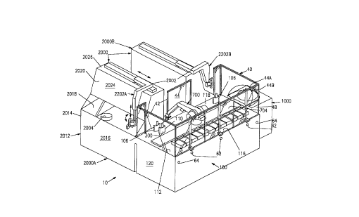
With reference to Figs. 1,2, 4, 8A, 9A, and 10A, a system 10 according to
the present invention co,.,p,ises, as its main components, a wolksldlion 100, a
centrifuge unit 1000, and at least one analyzer 2000, and typically two analyzers,
desig"ated 2000A and 2000B. The wo,ksldlion 100 is loaded with containers 12, such
as test tubes 102 (see Fig. 8A) by an operator. The test tube 102 is provided with
identificalion indicia, namely a bar code 104 and a cap 103. Typically the containers are
held in a holder 14, such as a sector 300 (Fig. 8A) or a test tube rack 600 tFig. 9A). For
centrifugation, the containers 12 are typically transferred to receptacles or buckets 1200
(Fig. 10A).
As shown in Fig. 2A, a pr~cess supervisor 200 of the system 10 includes
a detect input step 202 for detecting presence of con ~ ~er~ 12 at an input location 16
(Fig. 4) of the workstation 100. In a container select step 204, detectPd containers 12
are then selected for processing. Processing is on a first-in, first-out basis, except for
containers that need priority or "STAT" treatment. Those containers 12 are placed by
the operator within a priority region 18 on the workstation 100 for priority processing.
After a container 12 is selected for processing, the container ID, i.e., the
bar code 104, is read in a container ID read step 206, and main process components
are defined in a process select step 208, based on pr.,cessing specified for thecontainer 12. The container is then processed in one or more of a centrifugation step
210, a dec~rp..-g step 212, an analysis step 214, and an output sorting step 216.
For a specimen that is to undergo co",plete processing, the container is
sent by the centrifugation step 210 to the centrifugation subsystem for centrifuging in
the centrifuge unit 1000 (Figs. 16A-16G). The centrifuged container is then processed
in the dec~rping step 212 by a decapping subsystem 900 (Figs. 18A and 18B).
De~pped samples are then lranspoi led in the analysis step 214 for analysis on any
available analyzer. SUbS~nl;allY any type of analysis that is effective for biological
mal~,ials can be done, including analysis of urine, blood, and cerebrospinal fluid.
Moreover, the system 10 of the present invention can be used for industrial analysis,
and thus is not limited to biological substances.
... . , . _ ., ,
CA 022~839 1998-11-19
WO 98/01760 PCT/US97111718
After analysis on one or both analyzers 2000, the containers are returned
to the workstation 100, and then subjected to output sorting in the output sorting step
216, wherein each container 12 is put into a specified holder 14. Some of the holders
14 are for containers that will undergo further analysis or processing; other holders being
for containers whose pr~cessing is completed.
As further shown by Fig. 2A, containers 12 need not go through all of the
processing steps 210, 212, 214, and 216. For example, the woiksldlion 100 can beused just for output sorting. Altematively, it can be used for containers that do not need
centrifugation andlor decsi~p,ng, the supervisor 200 using the results of the process
10 select step 208 for determining s~ ~hsequent ones of the l~rocessing steps. For example,
appr~priale ones of the containers 12 can be sent straight to analysis and then output
sorting.
The centrifuge unit 1000, which is described in detail below, is designed
for centrifuging containers that are loaded in receptacles or buckets 1200 (Fig. 10A).
15 Each bucket 1200 holds multiple containers to be centrifuged, and the centrifuge 1000 is
adapted for centrifuging multiple buckets 1200, typically four. It is illlpo,ldnl for the
proper operation of the centrifuge and to avoid damage to the centrifuge, that burket~
loaded across from each other in the centrifuge have su~,slanlially the same weight,
within typically about 10 grams.
The centrifugation step 210 supervises the centrifugation subsystem
generally as shown in Fig. 2B. In the centrifugation subsystem, the buckets 1200 are
loaded in sele~d localions, and the localion for each container in each bucket is stored
in memory. The b~r4et~ are loaded in a predetermined order to be appro~i",ately
balanced as well as ,easonably permitted by the specific complement of containers 12
25 requiring centrifugation. Preferably the loading is monitored by a baiance system 800
(Figs. 17A, 17B) and the buckets 1200 are further balanced to comply with a
pr~dete",lined t~lerdnce. The balanced buckets are then loaded into the centrifuge
1000, centrifuged, and then u"lc~ded The individual containers 12 are then unloaded
from the buckets 1200 for further processing.
The analysis step 214 supervises the analysis subsystem generally as
shown in Fig. 2C, the containers 12 (typically the test tubes 102) being placed in sectors
CA 022~839 1998-11-19
WO 98/01760 PCT/US97/11718
19
300 and data corresponding to the particular sector in which the container is located is
stored in the memory of a process cor,l,-'lQr 500. As shown in Fig. 1 a loaded sector
300 is placed at a delivery site 106 of the workstation 100 by a robotic arm 700 of the
workstation 100 there being a delivery site 106 for each of the anaiyzers. An analyzer
robotic arm 2002 picks up the sector from the delivery site 106 and delivers it to an
analyzer transfer site 2004. The analyzer 2000 then proceeds to analyze the specimen
according to processi"g instructions from the process cont,-ller, and stores the results
of the analysis in the ",er"ory of the process cor,l ~ller 500. Then the analyzer robotic
arm 2002 picks up the sector 300 containing analyzed specimens from the analyzer10 transfer site 2004 and retums them to a workstation receiving site 110 The sector 300
at the vvo,kslalion ~eceiv;ng site 110 is then picked up by the workstation robotic arm
700 for sorting.
Fig. 2D shows the data and operating instnuction information flow
bet\,veen the various components of the system 10. The system includes the central
15 process controller 500 which can be typically a computer system. Exemplary of the
computer systems that can be used are industrial counterparts of co"""only available
32-bit personal computers having read-write memory in the several megabyte range.
The conl-vller 500 is provided a s~iP~'e input device such as a keyboard touch screen
card reader or another computer for inputting processing instructions into memory for
20 processing each of the containers 12 according to container identiricalion indicia.
The prucess conl~l er 500 provides instructions for mecl~an.~-' control of
the workstation 100 using fee~h~ck in the form of station status and sampJe
identificalion data. The analyzers 2000 are provided with respective cont,~ller:, 2008A
and 2008B as well as a separate conl,~llers 2010A and 2010B for the robotic arms25 2002. The analyzer cG,~ l'ers 2008A and 2008B can be commercially available
industrial microcomputers or counterparts of the process controller 500. Each of the
analyzer conl,.'lers 2008A and 2008B has an output inle~rdce for providing the central
CGI ILI ~ 1 ~r 500 information from each analyzer about availability whether the analyzer
can perform a particular test and test results. In retum the process conl,- er 500
30 provides test requestC to each analyzer 2000 for each specimen as well as operating
instructions through an input interface of the corresponding cont,.ller 2008A or 2008B.
Similarly, the prucess cont,~ er 500 provides to each of the analyzer robotic arm
cout.."ers 2010A and 2010B various load and unload instructions. Suitable devices for
CA 022~839 1998-ll-l9
WO 98/01760 PCTIUS97/11718
the analyzer robotic arm cor,l.~llers 2010A and 2010B are available from a variety of
industrial robot s~ rF' ers.
Based on the analyzer availability i..ro""alion provided by each analyzer
output to the central cont,lJller 500, the central c~nl,~"er selectively detemmines which
5 analyzer to use for each specimen. This can be effected by soft~,vare loaded in the
conl,~-l'er memory, where the software compares analyzer availability data against the
tests required by the specimen. The analyzer availability data includes what tests each
analyzer is capable of performing, and analyzer status inro,..,dtion, such as whether
reagents are loaded for particular tests and analyzer backlog.
The process conl,,Jl'er 500 also provides mechanic-' control instructions
to the centrifuge unit 1000, and receives status information from the centrifuge unit.
Optionally, the entire system can be inter~aced with a host computer 502.
The host computer 502 can be i,.le.raced with multiple systems, each system containing
a wo, hslation, a centrifuge, and one or more analyzers. The host computer can be used
15 for inputting instructions for each spec;men to the process conl,uller 500, and the test
results can be reported by the central process conl~cl'er 500 to the host computer 502.
The inte,races between the cb",ponents of the system, i.e., output
elemenls, output system elements, and input system, can be convenlional data
connections, such as RS 232 connectors with interconnecting cables, buses, and data
20 transport mechanisr"s such as IR transfer or direct hard wiring.
Lavout of SYstem Col"l~onents
As shown in Fig. 1, the v~c.hslalion 100 co",prises a table 112 having a
table top 114. The w~lkstation has a front or input section 116, a rear or analyzer
section 118, and two opposed sides 120. The front has placement locations for
25 placeenl of holders 14 for holding containers 12 that are to be processed, containers
whose processing has been cGI~rleled, and containers which have been partially
processed. Down the middle of the table is a track 704 for the robotic arm 700.
The system is ~d~pted to be used with many configurations of holders 14.
For example, it can be used for sectors 300 as shown in Figs. 8A, 8B, and 8C, which
hold a small number of test tubes 102. Sectors 300 are particularly useful for containers
which need to undergo identical processing. As detailed below, the v o(hslation robotic
CA 022~839 1998-ll-l9
WO 98/01760 PCTIUS97/11718
arm 700 has grippers 726 ~iarted to grip not only individual containers 12 but also the
sectors 300, so that a group of containers 12 can be lldnspo, led for various processing
steps simultaneously. The workstation 100 can also be used with racks 600, as shown
in Fig. 9, which are c~p~''e of holding multiple containers. The containers 12, which
typically are test tubes 102, are removed one by one from the rack 600 for processing.
Preferably the racks 600 are placed closer to the robotic arm track 704 than the sectors
300, to help speed up and increase the throughput of the system. On the analyzersection 118 of the worhslalion 100, there are located sectors 300 containing containers
for delivery to and to be received from the analyzers 2000.
As shown in Fig. 1, the workstation robotic arm 700 is prererably centrally
located on the table 112 for easy access both to the front input section 116 and the
analyzer section 118 of the table. Also, the centrifuge 1000 is preferably positioned at
one of the sides 120 of the workstation 100, for permitting operator access to the full
length of the front or input section 116 of the table 112, the rear or analyzer section 118
15 being reserved for access by the analyzers 2000.
In the layout of Fig. 1, the analyzers 2000 are positioned with their sides
pro~ ,ate to, and pr~ferably abutting, the workslatio,) 100, with the two analyzers 2000
being back-to-back. In the configuration of Fig.1, the worlcstation 100 does not interfere
with operation of either analyzer, and neither analyzer il,le,te,~s with operation of the
20 wo,kslalion. Moreover, the centrifuge 1000, being located at one of the ends of the
work:jlalion, is likewise out of the way of the analyzers and the worhslalion. The
analyzers are substantially identical, differing in that one (2000A) is "right armed" with its
robotic arm 2002A positioned to reach to the right to the workstation 100, and second
analyzer 2000B is "left armed" with its robotic arm 2002B positioned to reach to the left
25 to the workstation 100.
Figure 3A is a top plan view of the layout of the system shown in Fig. 1.
Altemative layouts are possible, such as shown in Figs. 3B-3F. The layout of Fig. 3B is
the same as that of Fig. 3A, except that the centrifuge 1000 is placed in a U-shaped
space formed by the workstation 100 and the two analyzers 2000, up against the back
30 2020 of the base 2012 of both workslations.
CA 022~839 1998~ 19
WO 98/01760 PCT/US97/11718
In the version of the invention shown in Fig. 3C, the layout is the same as
that shown in Fig. 3B~ except that the second analyzer 2000B is placed against the end
of the wo,k~ldlion 100 that is distal from the first analyzer.
In the layout of Fig. 3D, the two analyzers 2000 are placed on opposite
5 sides of the wurhslalion 100, thereby forming a "cross," with the right hand analyzer
2000A up against the rear 118 of the WOI hslalion and the left hand analyzer 2000B
against the front 116 of the workstation 100. The centrifuge 1000 is at one of the ends
of the wurkslalion, as in the layout of Fig. 3A.
The layout of Fig. 3E is similar to that of Fig. 3D, except the two analyzers
2000 are positioned at the centrifuge end of the worhstation 100 rather than in the
middle of the woihslalion. The layout of Fig. 3E is advant~geous cor"pa~ed to that of
Fig. 3D in that the workstation input side is not obstructed by either analyzer.
As is cvident from these various layouts, it is p~ le to posilion the
worhstation and centrifuge 1000 so that they do not obstruct access to either analyzer.
The ~u,k~lalion and centrifuge of the present invention are not limited to
use in direct conjunction with analyzers as shown in Figs. 3A-3E. Instead they can be
used with the conveyor system that includes a conveyor 126, as shown in Figs. 3F and
3G. In the version of Fig. 3E, the robotic arm 700 of the workstation picks up containers,
generally in sectors, from the conveyor 126, processes the containers, and optionally the
containers are centrifuged. Then processed containers are returned to the conveyor
126.
In the version of Fig. 3G the conveyor cooperates with the analyzer 2000
whose robotic arm 2002 picks up and delivers conlaL-er~, and/or sectors, to the
conveyor 126.
Analvzers
The analyzers 2000 shown in Fig. 1 are Synchron CX analyzer units
available from Bec,hl"an Instruments of Fullerton, Califomia, being modified or ,~l,u~illed
to incG,~or~le the robotic arms 2002 as described herein. As also shown in Figs.14A
and 14B, each analyzer 2000 has a base 2012 having opposed sides 2014, a front
2016, a top 2018 and a back 2020. The top 2018 has the analyzer l~ansrer site 2004
and analytical equipment lhereon and is accessible from the front by a user. A pedes
CA 022~839 1998-11-19
WO 98/01760 PCT/US97/11718
23
2022 is provided on the back portion of the top 2018 of the base 2012, the pedest~l
2022 having a front work area 2024 and a roof 2026. On top of the roof 2026 is al,anspo-l mechanism including the robotic arm 2002, for auto",ated lldnspGil of
specimens from the worhslalion 100 to the analyzer 2000, and for lldnspo,l of the
~ 5 analyzed specimens from the analyzer 2000 to the wo- kslalion 100. A path or track
2028 having a drive 2030 therein extends across the roof 2026 for moving the robotic
arm 2002 along the path 2028. The robotic arm 2002 has a track engaging element
2032, and an extension arm 2034 extending from the track engaging ele",ent 2032 in
the same direction the path 2028 extends. From the end of the exlension arm 2034,
there is a forwardly extending amt 2036, with a downwardly depending arm 2038 at the
end of the forwardly extending amm 2036. At the bottom of the forwardly extending arm
are grippers 2040.
Re~use of the extension arm 2034, the grippers 2040 can reach sectors
300 on top of the workbench 100. Moreover, in a "rest" position, the robotic amm 2002A
of the first analyzer 2000A is out of the way with regard to the top 2018 of the base 2012
and the front work area of the pedest~l and thereby does not interFere with processing
and operator access to the analyzers.
As further shown in Figs. 15A-15F the grippers 2040 of each analyzer
robotic arm 2002 are supported from a gripper aç~-~ator 2041, the actu~tor 2041 being
mounted on a bracket 2042 that is rigidly attached to an elevator member 2043 of the
robotic arm 2002. A crank member 2044 is movable about a vertical axis 2045 of the
actuator 2041 between first and second posilions through an angle of appro~in,dlely
180~ for selective opposite orienlational placement and recovery of sectors 300 at the
analyzer l,dnsfer site 2004 and at the wo,kslalion delivery site 106. A robotic clam
2046 is mounted to an end extremity of the crank member 2044 for movably supporting
an outwardly facing pair of hook-shaped gripper members 2048, each of the gripper
members 2048 being insertable through a respective top wall slot 322 of the sector 300,
the sectors 300 being described below in connection with Figs. 8A-8C. After suchinsertion, hook-shaped end extremities 2049 of the gripper members 2048 engage the
underaide of a top wall 306 (having the slots 322 formed therein) upon activation of the
clamp 2046 for separating the gripper members 2048. Also, each gripper member 2046
has an exl,aclor member 2050 vertically slidably engaged therewith, a vertically oriented
CA 022~839 1998-ll-l9
WO 98/01760 PCT/US97/11718
24
co",pr~ssion spring 2052 being intei ~,osed above the extractor member for biasins~ly
contacting the top wall 306 be~ocn the slots 322 when the gripper members 2048
extend into the slots 322. One purpose of the exl,dclor members 2050 is for insuring
that the sector 300 remains in place undisturbed when being deposiled at a site, the
extractors holding the sector down during ~ I,dld.lval of the gripper members 2048
during raising of the elevator member 2043. Another purpose of the exl,d-.lor members
2050 is for stabilizing the sector 300 on the gripper members 2048 during manipulation
by the analyzer gripper 2040.
A device s~l t-~le for the ~ctuatnr 2042 is available as Model
10 NCRB/BW30-180S rotary actllator, from SMC of Tustin, CA. A device suitable for use
as the robotic clamp 2046 is Model HGP-10-A gripper, available from Festo, of
Hauppauge, NY. Devices sui~hle for use as the analyzer track 2028 and drive 2030 are
available as Model IS-MX-20-200-400 robotic posilioning system with Model SA-A
vertical moving feature, from Intelligent Actuator of Torrance, CA.
With further reference to Fig. 13G, a preferred alternative configuration of
the gripper members 2048 for use with the sectors 300' includes one gripper member,
designated 2048', for engaging the resilient block 334, and a complementary gripper
member, designated 2048", for ~,ldr ~rr.. ,9 against the back wall 305 of the sector 300'.
Workstation
A layout of a prerer,ed workstation 100 or bench is shown in Fig. 4. This
layout is particularly adapled for having the centrifuge 1000 on the right side of the
workstation 100 as shown in Figs. 1 and 4. On the input section 116 of the table 112,
there are provided fifteen sort sites 128 labeled from left to right, as A-O, for sectors
300, and corresponding fifteen sort sites 130 A-O for racks for holding test tubes. The
track 704 for the robotic arm 700 extends down the middle of the table, extending from
end to end, dividing up the table into the input sections 116 and the analyzer section
118. The racks are closer to the track 704 than are the sectors, be~use there is more
travel of the robotic arrn associ~ed with the racks, where the containers need to be
loaded and unloaded one by one.
In a typical assiyl ""ent of the sector and rack sites, the input locdlions 16
include rack sites 128 and sector sites 130 labeled A-J, where new conla;ners to be
CA 022~839 1998-11-19
WO 98/01760 PCT/US97/11718
pr~cessed are located (including the priority region 18 at site A, for "STAT" specimens);
the output locations 17 include sites N and O, where sectors and racks having
completed p,ucessing and awaiting removal from the worl~slation 100 are located; and
the auxiliary region 19 include sites K-M, where sectors and racks having spec;",ens
- 5 ready for analysis are loc~ted, such as for a first analysis by one of the analyzers, or for
specimens having already been analyzed by one analyzer and are ready for a second
analysis process on a second analyzer. It will be underalood that the particular division
of functions for the localions on the input section 116 can vary depending on the
throughput rates of the analyzers, the number of analyzers available, and other factors,
and the assignments can differ as between the rack sites 128 and the sector sites 130.
The racks 600, which can be provided with a bar code ide"liricalion 601,
are used for storing and/or sorting test tubes, and as a way of removing and placing
large quantities of test tubes on the workstation. The sectors 300, although having
smaller capacity, can be picked up by the robotic arms 700 and 2002, being used not
only for processing but also for sorting multiple test tubes simultaneously, thereby
adding to the erric;ancy of the workstation 100.
The workbench of Fig. 4 is adapted for use with at least two analyzers.
Thus, a "launch pad" 105 at each end of the analyzer section 118 has the delivery site
106 for pickup of sectors by the analyzer robotic arm 2002, and the receiving site 110 for
delivery of sectors containing analyzed sa",F'es from the robotic arm 2002. Surrounding
the launch pads are a plurality of sector locations 134 being used for empty sectors, or
for locating loaded sectors at peak processing times when the input section is full.
In the middle of the analyzer side are buckets or receptacles 1200, and a
scale 802 and an ~ ~ rack site 804 of the balance system 800. Figure 4 shows four
buckets or receptacles 1200 on the scale 802 for balanc;, -g, the auxiliary site 804 having
a rack 600 for dummy test tubes 806 that are used for balancing out the weight of the
loaded buckets. To the right of the auxiliary rack site 804 is the de ~p,-ng system 900,
fcll~/cd by four buckets 1200 either being unloaded after centrifuging, or being loaded
with new test tubes for centrifuging.
With further reference to Figs. 20A and 20B, a preferred configuration of
the table 112 includes a base 20 having a parallel-spaced pair of beam members 22 that
connect a spaced plurality of bulkheads 24, the bulkheads 24 having respective column
CA 022~839 1998-11-19
WO 98/01760 PCT/US97/11718
pGI lions 25 that support a rail member 26.of the track 704. Each of the bulkheads 24
also anchors a pair of column members 28 on the beam members 22 the input and
analyzer sections 116 and 118 of the table 114 being sepa.dtdly fastened on top of
respective rows of the column members 28. By this construction, the table 112 can be
5 conven,e.ltly stored and L.dnspo,lad as one cG,l,pacl pao~ge including the beam
members 22, the rail ~-,el, Iber 26, and the sections 116 and 118, and anotl ~er cGrl Ipac
package including the bulkheads 24 having the column me,llber~ 28 fastened thereto.
There are five of the bulkheads 24, the spaces lher~betv.~0en defining four bays for
accol"l"odaling various power distribution and electronic compGnents of the system 10
10 in a conventional manner. Under each end bulkhead 24 is mounted a pair of swivel
casters 130 for rollably supporting the workstation 100, and an adjustable foot assembly
132 is spaced inwardly from each end and mounted under each beam member 22 for
leveling and ancl-oring the table 112 in a conventional manner.
A typical workslalion has a length of about 2.83 meters, and an overall
width of about 980 mm, with the input section being about 540 mm wide, a track width of
about 145 mm, and the analytical section being about 440 mm side.
As further shown in Fig. 1, the workstation 100 is preferdbly provided with
a protective shield system 40 for blocking operator intrusion within space above the
table top 114. The shield system 40 has a frame 42 on which are mounted a plurality of
lldnspa,~nt panel members 44, being vertically oriented proximate the perimeter of the
table top 114, the shield system 40 being interrupted along the rear section 118 for
clearing the respective analyzer robotic arms 2002A and 2002B. The panel member
proxi",ate the centrifuge unit 1000, designated 44A, has a bubble exte,)sion 46 formed
therein for inclusion of a path to the centrifuge unit 1000 within the shield system 40.
Also, and with further refert:nce to Fig. 21, the panel member along the front section
116, designated 44B, extends down only partv~ay from the top of the frame 42, three
tl anspart:nl door panels 48 being supported for vertical movement in overlapping
relation with respective po, lions of the panel 44B. Each of the door panels 48 is
coupled to a piston rod 50 of a pneumatic ~ctll~tor 52 by a handle clamp assembly 54,
the ~ctu~tor 52 being mounted to a top portion of the frame 42. A solenoid latch 56 is
located within the table 114 in assoc:~t;on with each door panel 48 for locking same in a
closed posilion thereof. In an exel"plary configuration as shown in Fig. 21, the solenoid
latches 56 when deactivated engage Jiscontinuities or slots 58 that are formed in lower
CA 022~839 1998-11-19
WO 98101760 PCT/US97111718
27
exl,an,ilies of the piston rods 50; activation of the latches 56 ~ le~ses the rods 50. The
door panels 48 are reinforced against excessive inward force by the handle clampasse", I.es 54 having depending projections 60 thereon that extend proxi",alely against
an edge extremity of the table top 114 in the closed positions of the panels 48. A door
5 button 62 is located under each handle clamp assel"bly 54 for signaling an associated
door open request to the process controller 500. Subject to appr~pridle interlocks and
process suspension the co"esponding latch 58 is activated f~l ~wed by activation of
the co"asponding pneumatic ~ctl~ator 52 whereupon the door panel 48 is raised for
operator access to the input section 116 of the ~horkslalion 100. The workstation 100 is
10 pr~ferdbly provided with two e,,,eryency stops 64 one proximate each end of the input
section 116, for use by an operator.
With reference to Fig. 5 there are provided two sector reg;sl,dlion posts
or pins 142 for each sector 300. Similarly two rack positioning pins 146 are provided for
locating each rack 600 that is on the workstation 100. A table magnet 145 is mounted
flush with the table top 114 in predetermined relationship with pairs of the pins 142 and
146 for attracting respective holder magnets 330 of the sectors 300 and the racks 600
as further desc,ibed below. Also there are two bucket locator pins 144 on the
work~lalion 100 for each receptacle or bucket 1200 used for the centrifuge. Figs. 6A-6C
showatypicalsectorpin142 rackpin146 andbucketpin144 respectively. The
particular shape of the pins is selected so they cooperate with the respective devices
they serve to locate. As shown in these figures the three types of pins are different to
inhibit operators from misloc~tirlg the devices on the workstation. As further shown in
Figs. 6A-6C the pins 142 144, and 146 on the table 114 are located in shallow wells
156 for confining any inadvertent spillage from the containers 12. Co~.nte"~a, ls of the
wells 156 are also provided on the scale 802. Further a perin~elar trough 158 is forrned
in each of the front and rear sections 116 and 118 of the table 114 and surrounding the
various sites for the holders 14 as shown in Fig. 6A.
The cooperation between the sector pin 142 and a sector 300 is shown in
Fig. 8A; the cooperation between the rack a 600 and the rack locating pins 144 is shown
in Figs. 9A and 9B and the relalionship between a centrifuge bucket 1200 and thebucket localion pins 146 is shown in Fig. 10C which shows the pins 146 in an
alte",ati~e configuration of the centrifuge 1000.
CA 022~839 1998-11-19
WO 98/01760 PCT/US97/11718
The work ~lalion is provided with a deteclion system for de~ecting the
presence of sectors and racks on the workstation. In a pr~:rer,~:d version of the invention
shown in Fig. 7 there is used a sensor or reed switch 150 which is recessed slightly
below the top surface of the workstation. Each reed switch 150 is retained by a flush-
fitting plug member 152 that is removable for facilitating ser~icing and/or replace"~enl of
the reed switch 150. Plt:rerdbly electrical circuits of the reed switches 150 are provided
with suitable connectors (not shown) for facilitating ,~pla~r"ent of the switches 150
without requiring access below the table top 114. The locations of the reed switches
150 are shown in Fig. 5. The reed switches can be activated by providing the sectors
10 racks and buckets with ",agnets strong enough to activate the reed switch. Also other
detection systems can be used including weight systems where the dePctor detects the
presence of a sector or the like by its weight; or a detector system that relies on an
electrical current where the presence of a sector or rack closes a circuit so electrical
current can be detected; or an optical interrupter where the device interrupts a light
15 path.
An exemplary sector 300 as shown in Figs. 8A 8B and 8C includes a
base 301 having a convex front wall 302 a concave back wall 304 a bottom wall 308
and side walls 310. A top 315 snap fits onto the base 301 and includes a a top wall 306
that extends rearwardly and outwardly from portions of the side walls 310 of the base
20 (the side walls 310 being slaggered for clearing the sector positioning pins 142 of the
workstation 100, thereby forming an overhang 318 which has two holes 320 therein for
the pins 142. Along the front wall 302 are tubular cavities 314 for test tubes 102 and in
the version shown in the figures there are seven such cavities. They extend from the
top wall 306 and can drain through the bottom wall 308. Each cavity 314 has a slot 316
25 in the front so that a bar code reader can read the bar codes 104 on the front of the test
tube 102. In the top wall 306 are two slots 322 which can be engaged by the gripper
",er"b~,:, or jaws 2048 of the analyzer robotic arm 2002 (Figs. 15A-15F). The slots 316
extend partially in the base 301 and partially in the top 315.
Extending upwardly from the top wall 306 of the sector 300 is a
30 counle"~a, l of the back wall, designated 305, from which projects a T-shaped handle
324 the combination of the back wall 305 and the handle 324 being engageable by the
gripper element 726 of the wo, kslation robotic arm 700 (Fig. 13C).
CA 022~839 1998-11-19
WO 98/01760 PCT/US97/11718
29
The front wall 302 of the sector 300 is provided with a bar code 326 to
identify and allow the central conl,.ller 500 to track the sector and the test tubes
therein. The base 301 is also provided with an internal bar code strip 327 which is
visible when a test tube slot 316 is empty but t l~ ~ ~?d when a test tube is in the slot.
- 5 Thus a bar code scanner 724 (Fig.13A) can signal the central processor 500 with the
number and localion of test tubes in each sector. A holder magnet 330 is mounted flush
with the bottom wall 308 for stabilizing the sector 300 and holding the sector in place on
the wo,kslalion 100 during removal of test tubes 102. The holder magnet 330 is located
and oriented for attraction by respective ones of the table magnets 145 of the
workstation 100. A sensor magnet 332 is likewise mounted flush with the bottom wall
308 for activation of respective reed switch sensors 150 of the workstation 100.
With further reference to Fig. 8D an altemative and prefe"ed
configuration of the sector designated 300' has the back wall 305 (and the handle 324)
extended somewhat from the top wall 306 and having a rearwardly pr ,e~li"g lip portion
305 a triangularly shaped resilient block 334 being retained on the handle 324
proxi",ately against the underside of the lip portion 305'. The resilient block 334
advantageously facilitates reliable engagement of the sector 300' by the grippermembers 2048' and 2048 ' of the analyser robotic arms 2002 in the configuration of Fig.
13G by pe""illing increased vertical (and l,ori ontal) alignmenttolerance as compared
with the engagement configuration of Fig. 15E. The resilient block 334 also facilitates
more effective gripping by the gripper members 726 of the wGrkslation robotic arm 700
in the configuration of Fig. 13D by resilient conro""ily of the block 334 with one of the
gripper "~embers 726 and by the co",'~inalion of the block 334 and the back wall 305
having a non-circularly cylindrical shape the engagement producing a centered and
vertically aligned relationship between the sector 300' and the gripper axis 715regardless of slight vanalions in vertical positioning of the gripper members.
RecAuse laboratories typically process specimens from different sources
such as different hospi~lc testing labs and doctors offices the containers or test tubes
102 often have different dia"~eter~ and ~Jifferen~ heights. To accG"""odale varialions in
dia,~,èlers the top 315 has four depending fingers 328 for each test tube slot 314 the
fingers being biased radially inwardly. The sector 300' shown in the Figure 8D is
available from Beck~"an Instruments with the Synchron CX machine.
CA 022~839 1998-11-19
WO 98/01760 PCT/US97/11718
With ~fer~nce to Figs. 9A-9D a test tube rack 600 suitable for use in the
system 10 includes a frame 602 having the bar code ide, llifier 601 applied thereto and
defining a 5 by 10 array of vertical cavities 603. The frame includes holes 604 for the
positioning pins 146 and has counterparts of the holder and sensor magnets 330 and
332. Each of the cavities 603 is provided with an insert member 606 having spring
fingers 607 to hold dirrer~nl size test tubes in the rack the fingers being formed for
retaining a resilient O-ring member 609 that auylllenls ~ lional engage",enl of
containers 12 being test tubes 102 by the fingers 607. Thus each rack 600 forms a
holder 14 for the containers 12 the cavities 603 being typically spaced at a pitch of
10 appr~,xim3t~1y 20 mm the inserts 606 being sized for biasinyly centering the containers
12 up to appro~(i",ately 16 mm in dia",eler the combination of the finger members 607
and the O-ring 609 being sufficiently resilient for effectively centering containers not
largerthan approxi",dtely 13 mm in dia",eler.
Although the present invention is des- ,iL,ed with regard to bar code and
bar code readers for tracking test tubes and other components of the system other
detection systems can be used. For example magnetic ink labels can be placed on test
tubes and other cor"poneril~ to be read by a magnetic ink reader.
With reference to Figs. 10A 10B and 10C the buckets or receptacles
1200 each have an array of cavities 1203 cor,t sponding to the openings 603 of the
20 racks 600 the cavities 1203 symmetrically surrounding a stem member 1204. An upper
portion of the stem member 1204 is square in cross-section for engagement by thegripper members 726 (Fig.13C) of the robotic arm 700 in any of four discrete orthogonal
orielltdliGns a spaced pair of resilient O-rings 1206 being retained on the stem member
for augmenting r,iolional engagement by the gripper members 726. As shown in Fig.
25 10A there are 16 of the cavities 1203 in each recept~cl- 1200 each cavity 1203 being
defined by a counterpart of the insert 606 and having counterparts of the fingermembers 607. The recept~r'es 1200 are adapted for placement in respective cradles
1008 of the centrifuge unit 1000 having a pair of notches 1208 formed in oppo~ sides
thereof for reg;..l,dtion with respective bearing caps 1009 of each cradle 1008 as shown
30 in Fig.10A.
As shown in Fig. 10C each recept~~le 1200 is formed with a pair of holes
1210 for reg;;.l,dtion on cG"~ponding bucket positioning pins 144 and a counterpart of
CA 022~839 1998-11-19
WO 98/01760 PCT/US97/11718
the sensor magnet 330 for activation of the Associc~'ed reed switch sensor 150 of the
wo, kslalion table 114 (Fig. 5). Optionally and a further shown in Fig. 10C, a counterpart
of the sensor 150 can be located in or under the cradle 1008 for sensing a seated
cGn~Jilion of the ,t:cepl~cl~ 1200 in the centrifuge head 1006, and/or counterparts of the
- 5 positioning pins 144 can be mounted on the cradle 1008 as an alternative to reg;sl,dLion
of the receptacle 1200 by the bearing caps 1009.
When loading buckets with test tubes for use in the centrifuge, it is
i",po,ldnt they be loaded in a systematic way to provide balance. Figures 11A-11 D
provide a top plan view of recept~cles 1200 loaded into the centrifuge, showing
sali~raclory loading pattems. Empty test tube cavities 1203 are represented by unfilled
circles, blackened circles representing cavities loaded with test tubes 102. The buckets
are loaded to provide even weight on opposite sides of the center point of the
centrifuge, as well as maintain each receptacla approxi",~tely balanced relative to the
respective stem member 1004. Other s~ 'e loading patterns are known to those of
ordinary skill in the art.
With particular reference to Figs. 13A, 13B, and 13C, an exei "plary
configuration of the robotic arm 700 includes a base Cdl I iage 702 that is posilionable
along the workslalion track 704. The track 704 extends proxi",dlely between opposite
ends of the wo,k~lalion 600 approximately centered between opposite sides thereof,
and having protective accordion covers 705. A panning head 706 is conl,~ ly
rotalably supported on a vertical pan axis 707 of the base carriage 702, an upper arm
708 being likewise controllably ,otalably supported on a hon~onldl shoulder axis 709 of
the panning head 706. A lowerarm 710 is likewise cont~c'!2bly rotatably supported on
an elbow axis 711 of the upper arm 708, the elbow axis 711 being parallel-spaced from
the shoulder axis 709 at an outer extremity of the upper arrn 708. Similarly, a wrist head
712 is conb~ ly rulalably supported on a wrist axis 713 of the lower amm 710, and
having a gripper head 714 conl(."-' ly roLalably supported therefrom on a gripper axis
715. The axes 713 and 715 are orthogonal, the wrist axis 713 being parallel-spaced
from the elbow axis 711 at an outer e,~ n,ily of the lower arm 710. The gripper head
714 has a gripper body 716, pair of gripper armatures 717 being conll."~'~ly movable
with tactile feedha~.k toward and away from oppo il9 sides of the gripper axis 715. The
gripper head 714 also includes an optical head sensor 718 fixably SU~Jpoi led relative to
the gripper body 716, the head sensor 718 including a light source 719 having a source
CA 022~839 1998-11-19
WO 98tO1760 PCT/US97/11718
32
axis 720 and a light portion 721 having a .ecsiver axis 722 the axes 720 and 722converging proAi",ale the gripper axis 715 from opposile sides thereof in spaced relation
to the gripper body 716 and the gripper armatures 717. The robotic arm 700 also
includes a robot control system (not shown) having suitable provisions for manipulating
5 the gripper head 7t4 relative to the wu,k~lalion track 704 for y, r ..g and transporting
objects in a ~nanner known to those having skill in ~botics. As so far described the
exe."plary robotic arm 700 is a commercial device, available as Model 255 from CRS
Robotics of Ontario Canada.
As further shown in the drawings the robotic arm 700 is provided with an
indicia scanner 724 so",eli",es referred to herein as bar-code scanner 724 the scanner
724 having a scan axis 725 and being fixedly located on the upper arm 708 such that
the scan axis normally intersects the gripper axis 715 distally from the intersection of the
source and receiver axes 720 and 722. Thus the scanner 724 is advant~geously
o, iented on the upper arm 708 for permitting effective scanning of both vertically and
1 ~ ho, i~o"tally oriented indicia. Particularly, the container indicia 104 are normally vertical!y
oriented while the various indicia of the racks 600 receplacles 1200 and sectors 300
are normally l,o,i~Gnlally oriented. Moreover the gripper head 714 is provided with a
pair of gripper members 726, the gripper members 726 being mountable on respective
ones of the gripper armatures and being adapted for grasping containers receptacles
and sectors as described herein for transport thereof. Further the head sensor 718 in
cG",~.nalion with progr~l,l"~ed movement of the gripper head 714 permits
determinations of the heights of the containers 12 for effective engagement by the
gripper members 726.
As further shown in Fig.13B the robotic amm 700 is movable about the
pan axis 707 within an angle ~ that is sy"""et,ical on opposite sides of the u~clksldlion
track 704 and greaterthan 180~, being approxi",ately 31~~. This range of angularorientations about the pan axis 707 in combination with the base carriage being
movable to proximate each end of the workstation 600 facilitates transport of containers
12 sectors 300 and other holders to virtually any location within the table 114 often
without requiring movement of the base carriage 702 along the work~ldliol) track 704.
Also, the gripper head 714 is advanhgeously loc v~'e in overhanging relation to the
table panel 114 for accessing the centrifuge unit 1000.
CA 022~839 1998-11-19
WO 98/01760 PCT/US97/11718
With further reference to Fig. 13D, an altemative configuration of the
gripper head 714 has the head sensor 718 on one side only of the gripper body 716, a
laser source 719' being s~ ~hstit~ ~ted for the emitter 719 and mounted adjacenl the light
receiver 721. Thus the source and rt:ceiver axes 720 and 722 converge from the same
side of the gripper axis 715; however, the laser source 719' more than compe"sales for
any loss of effectiveness of the sensor 718 that would be attrihut~"ie to the axes 720
and 722 being asymmetrical relative to the gripper axis 715.
Site Adiusters
The ~ slalion delivery site 106 and receiving site preferably are
10 provided with a site adjustment mechanis", 961 for each of the analyzers 2000, each
adjustment mechanisr,) 961 facilitating exchanges of holders 300 between the
workslalion 100 and the cG"esponding analyzer 1200. As shown in Figs. 12A and 12B,
the delivery site adjuster 961 includes a plalrGlr" member 962 and a clamp member 964
that are movably coupled on opposit~ sides of the table panel 112 of the wc" kstalion
15 100 by a plurality of threaded fasleners 965, the fasteners 965 and a boss portion 966
of the pldtrolrrr member 962 extending through a clearance opening 967 that is formed
in the table 112. Each of the fasteners 965 carries a compression spring 968 for biasing
the platrGI~n member 962 and the clamp member 964 into clal.,ping engagement with
the table panel 112, the pldrolrn member962 also having an O-ring 969 partiall
20 recessed therein for frictionally ~,ipp,g the table during the clamping. A pneumatic
cylinder 970 is coupled between the clamp member 964 and the boss portion 966 of the
pldlroll-- member 962 for releasing the c.la.., ~9 in response to selective a~Fli~ ~tion of
pressurized gas to a gas port 971 of the pneumatic cylinder 970 by a gas pressure
system 850 (Fig. 19). Thus the plaUol,n member 962 is freely ~utat~ ~.'e and laterally
I,dns' '~~.'e while the pneumatic cylinder 970 is activated. The platrollll member 962
has two pairs of the loc~ling pins 142 mounted II,ereon for locating and holdingcorresponding sectors 300 thereon, the sectors 300 being accessible by either the
wor~sldtion robotic arm 700 or the co" ~sponding analyzer robotic arm 2002. Also, the
pldlrollll member 962 has sensor~ 150 imhedded therein for sensing correspondingsectors 300 being .eg;sterl3d on the acsor.i-ted pair of pins 142, each sensor 150 being
typically implei"enled as a conventional magnetic reed switch and coupled for signalling
with the prucess conl~.."er 500.
.. . . .... ..
CA 022~839 1998-11-19
W O 98101760 PCTAUS97/11718
34
Once each analyzer 2000 is set up in pru,~i.,,dle alignment with the
wo,kslalion 100, the asso~ialed alignment mechani;"" 961 is adjusted by first activating
the pneumatic cylinder 970 for releasing the clsll,F.ng, then manually positioning and
o~ienling the platrurl,, member 962 for alignment of the sectors 300 with the analyzer
gripper 2040 in co"t:aponding wo,l~slalion l,~nsrer positions of the analyzer robotic arm
2002. The pneumatic cylinder 970 is then released for clamping the plalrG~ member
962 in the aligned position, thereby efrectin~ the adjustment. Finally, the posilion and
orientation of the plafform plate 962 is stored in memory of the process conl,.l'er 500 by
any suitable means, such as by scanning the sectors 300 in seated posilions thereof on
10 the pWo"" member 962 using the optical head sensor 718 of the workslalion robotic
arm 700.
Balance S~stem
As indicated above, and with particular reference to Figs. 4,17A, and
17B, the prucessi"g system 10 includes a balance system 800 for balar,cing containers
15 12 in receplA~ les or buckets 1200 prior to centrifugation, the balance system including
the scale 802 and the auxiliary rack site 804 on the rear section 118 of the workstation
100. The scale 802 can be a conventional electronic plalro"" scale to which is added
counte(pa,ls of the bucket positioning pins 144 for locating the ,eceptacles 1200.
Buckets are moved bEt~/ecn the scale 802, the centrifuge unit 1000, and other locations
20 on the rear section 118 by the unJ~ ldlion robotic arm 700, which also transfers
containers 12 to bucketc 1200 on the scale 802 from a rack 600 at the auxiliary site 804
as well as from other localions on the workstation 100. The balance system 800 also
includes a balance co"t~ller for selectively depositing containers in cavities of the
,~cepl~-les while correlating incremental weight changes with the locations of each
25 deposit for equalizing weight in pairs of the receptacles. The balance cont,~"er can be
implemented as a balance p,uy,dr" 808 within the central process cont,~ller 500, the
balance progra", 808 maintaining a dalAbase 810 of container loc~lions and associated
wei,Jllls, and directing the robotic arm 700 for deposili"g the containers 12 into the
receptacles 1200 in ,~sponse to weights measured by the scale plalroi", 802, the30 v eigl,ls being signaled in any suitable manner to the process conl,~l'sr 500.
Pl~fe(ably the balance system also includes a supply of dummy loads
806 (which can be test tubes 102 that are loaded with predetermined v.eights) to be
CA 022~839 1998-ll-l9
WO 98/01760 PCT/US97/lI718
selectively cJeposiled into the receptacles 1200. Accordingiy the balance conl~l'er is
operative for moving dummy loads 806 to apprupn~le localions in particular receplacles
1200 for limiting weight va~ialions between rer~ptacles. rl~ferc,bly the dummy loads
806 are progressively u ei~l ,led for limiting the weight \idl ialions in pairs of the
receptacles 1200 to not greater than 10 grams. The auxiliary rack site 804 is provided
on the workstation 100 proximate the scale 802 for facilitating te,.",~o~,y storage of the
dummy loads 806 the rack 600 at the site 804 also providing adclitional te",pordry
stc,rdge for containers 12 to be further processed and/or sorted.
In the balance pr~,g~",808 the scale cl- l~h~se 810 is initially loaded in a
select specimens step 8t2 with counterparts of container indicia 104 and with data for a
cGr"",on spin cycle 1002 acsoci-ted therewith the co"~ponding containers 12 being in
a quantity appr~p,iale for simultaneous centrifugation by the centrifuge unit 1000. Next
in a tare step 814 an apprupriate col"rler"ent of receplaclas 1200 for holding the
containers 12 is identified and seated if necessary at respective sites on the scale
plafform 802. A total load on the scale 802 is measured fallowing the depositi"g of each
item on the scale 802 a difference between successive measurements representing
each particularadded load. Flo"rJ~; ,g the tare step 814 is a load step 816 wherein the
containers 12 to be centrifuged are sequentially placed in respective ones of the
,ecep~acles 1200 according to an app,opriate one of the pattems of Figs. 11A-11Ddepending on the number of the containers 12 to be centrifuged. The balance program
808 continues monitoring the loads added to the scale 802 during the load step 816.
Thus the balance program 808 is operative fomllonilo~ g the total weight ~ssocialed
with each of the r~ceplacles 1200. After the load step 818 approp, iale ones of the
dummy loads 806 are added in a correction step 820 as required to bring members of
each pair of the recepta~ es 1200 to within the predetermined allowable variation
Der~r Per SYstem
With particular reference to Figs.18A and 18B the decapper system 900
- includes a receiver 902 for clampingly holding a container or test tube 102 having a cap
103 frictionally engaging the test tube 102 and extending laterally from opposite sides of
a top portion of the test tube 102. The receiver 902 is mounted in depending relation to
a der~pper deck insert 903 of the worksl&lion 100 as further described below. Ani""~o, lanl aspect of the present invention is that the decapper system 900 is operative
.
CA 022~839 1998-11-19
WO 98/01760 PCT/US97/11718
36
with both threadingly engaged caps as described below, and with caps having r,iclional
engagement only with the container 12 as desc,il,ed herein. A yoke member 904 having
a cap slot 905 formed therein is movably mounted on an elevator 906 that pr~,Pcts
above the deck insert 903, being SUppGI l~d thereby. The elevator 906 includes an
actl ~tor 908 and an elevator column 909 that is rigidly connected to the yoke member,
the actl ~tor 908 being coupled to a ~dnsldtion motor 910 through a l~nslalion belt 911
for rotaliol)al ll dnslalion of the yoke ...ember 104 ~, ~cent, ic with the elevator column
909 betwecn open and closed posilions thereof. The elevator 906 is also coupled to an
elevator motor 912 through an elevator belt 913 for raising and lowering the elevator
column together with the yolce member 904. The yoke member 904 has an upwardly
facing ledge portion 916 formed within the cap slot 905 for engaging the underside of an
outwardly extending shoulder surface 917 of the cap 103 when the cap 103 is seated in
the test tube 102, the tube 102 being held in the receiver 902, in the closed position of
the yoke member 904.
With the ledge portion 916 extending under the shoulder surface 917 in
the closed posilion of the yoke member 904, the elevator 906 is operative for raising the
yoke ,ne,-lber 904 relative to the receiver 902 to thereby remove the cap 103. The
receiver 902 includes a bladder cage 920 for rigidly SUppGI tiny a bladder 921, the
bladder 921 having a gas port 922 for selective inrlalion from a s~ ~it~'~le pressure source,
described below, thereby to grip a test tube 102 being seated therein. Thus the receiver
902 is operative for holding the container 12 against axial forces exerted by the yoke
member 904 as the cap 103 is being pulled from the container 12.
As ..,e.,lioned above, a further i",poilanl capability of the decapper
system 900 is removal of threadingly engaged caps 103. Accordingly, the bladder cage
920 is rolatably mounted to the deck insert 903, being coupled to a rotation motor 924
through a . ulalio, ~ belt 925 for conl, . " ~ly tuming the bladder 921 concenll ically with the
container 102, thereby to unscrew the container 12 from the cap 103. The cap 103 is
prevented from rotation within the yoke member 904, being formed with a non-circular
outer contour having an enlarye",ent 927 formed thereon, the enlargement 927 of the
cap 103 bearing against a portion of the cap slot 90S when torque is applied to the
container 12 by the retainer 902. The gas port 922 is preferably configured to provide a
rotary connection to the bladder 921, the port 922 being connected to a three-way
CA 022~839 1998-ll-l9
WO 98/01760 PCT/US97/11718
control valve 928 through a cage line 929 for selective pressure activation in response to
the central conl(. er 500 to effect the above-described holding of the containers 12.
With further reference to Fig. 18F a pr~re"ed altemative of the bladder
cage designated clamp cage 920 includes a resilient sleeve 921 in place of the
bladder 921 the sleeve 921' having three outwardly pr~ zcting ears 926 that engage
respective ear slots 929 of the cage 920' to insure ,olalional integrity of the sleeve 921
with the cage 920. Three vertically oriented jaws 913 are spaced bEt ~eon the ears 926
together with cG"~sponding cam bars 914 the bars 914 resting on a disk plate 915. An
air cylinder 918 that is coupled by the fitting g22 to the control valve 928 through the
10 cage line 929 drives the disk plate 915 and the bars 914 upwardly. The bars 914 have a
spaced pair of cam slots 914A that engage co"esponding pins 914A that project from
the jaws 913 thereby driving the jaws 913 inwardly in ,~sponse to the upward
movement of the bars 914 for compressing the sleeve 92i against the test tube 102.
The sleeve 921 is closed at the bottom for confining debris in case a test tube 102 is
15 fractured therein. Also the sleeve 921 has ribs 923 formed therein for contacting the
test tube 102 including three full-length clamp ribs 923A that are aligned with the jaws
913 and three foresl-o, lened holder ribs 923B. Spaces between the ribs 923 contribute
flexibility to the sleeve 921' for enhanced effectiveness of the jaws 913 in gripping the
test tubes 102. Test tubes 102 that are 100mm in length normally extend to proximate
20 the bottom of the sleeve 921' while test tubes 102 having a length of 75mm are
normally inserted only partNay into the sleeve 921 as indicated by broken lines in Fig.
18F the holder ribs 923B being configured for retenlion of the shorter test tubes 102
partially inserted without adding unnecessarily to the axial forces required for full
inse,lio" and ~;tlnJIavval of the 100mm test tubes 102.
Preferably the decapper system also includes a collector 930 for receiving
caps 103 from the yoke member and an unloader 932 for lldnsfe"i"g removed caps
from the yoke member 904 to the "A I ector 930. An exe",plary implementalioll of the
unloader includes an upstanding un o ~der post 934 fixedly mounted to the deck insert
903 proxi",ale the COIl~ ~ A r 930 in alignment with the cap slot 905 in the open position
30 of the yoke member. A dec~ ~per proy,~m portion of the central oont,-l er 500 is
operdli~/e for moving the yoke member 904 having a removed cap 103 therein until the
post 934 strips the cap 103 from the yoke member. Preferably the ~c lector 930 further
inciudes a tube me,-,ber 936 for directing the stripped caps 103 into the ~A'Iector 930.
CA 022~839 1998-ll-l9
WO 98/01760 PCT/USg7/11718
38
With further reference to Figs. 18C-18E, an alternative and preferred
configuration of the de~pper system, designated 900', includes a yoke housing 938
having a bottom cover 939 as a counterpart of the yoke member 904, a clamp
mechan;;"" 940 being operative within the housing 938 for positively gripping the caps
103. As shown in Fig. 18E, the clamp mechanis-" 940 has an opposed pair of pivotally
mounted jaws 942 that are operated by a pneumatic cylinder 944 having a wedge-
shaped cam ~ctu~tor 946 that extends from the cylinder 944 in response to applied gas
pressure. The jaws 942 are each formed having a plurality of pr ,e ~icns 943 therein for
gripping opposite sides of the caps 103 when same are positioned within the cap slot
10 905. The yoke housing 938 is formed having a p~ssage 948 therein from the cylinder
944 to a fitting 949 that pr~ect~ below the cover 939 for connecting a flexible line 950,
the line 950 extending below the deck insert 903 to a three-way valve 952. The valve
952, being connected by a dec~-per line 870 to the pneumatic system 850 (Fig. 19) as
is the valve.928 described above, is operative for activating the pneumatic cylinder 944
15 in response to the central conl.~"~r 500 to effect gripping of the caps 103. Thus the
caps 103 are not required to have enlargements 927 or to oll ,e~ ise have a rotationally
interfering fit with the cap slot 905. Further, the caps 103 are not required to have the
outwardly projecting shoulder surface 917 (Fig. 18A) in the prere"l:d decapper 900'.
As further shown in Figs 18C and 18D, the dec~rper system 900'
includes a counterpart of the u.. !Q~der 932 on the yoke housing 938, in the form of a
plunger assembly 954. The plunger assembly 954 includes a shouldered plunger 955that is guided within an ejector support 956, the plunger 955 having an upwardlyprojecting stem 957 that slidingly engages the support 956, an ejector spring 958 being
interposed on the stem 957 for downwardly biasing the plunger 955 against the yoke
housing 938. A cap 103 being released from the jaws 942 by deactivation of the valve
952 is forcefully extracted from the cap slot 905 by axial movement of the plunger 955
into engagement with the yoke housing 948. Thus caps 103 are prevented from sticking
to the p,.,ections 943 of the jaws 942 when the clamp mechanis",940 is opened, for
reliable unloading into the ~I'ector 930.
The conbe"er 500 is p(uylallllned for driving the elevator 906 sufficiently
high for the plunger 955 to clear the cap 103 as the cap slot 905 is rotated into position
over the cap 103, then lowering the yoke housing 938, thereby cG..,,uressing the ejector
CA 022~839 1998-11-19
WO 98/01760 PCT/US97/11718
39
spring 958 as the jaws 942 are lowered into a desired aliy' .r.,enl with the cap 103, the
cap 103 supporting the plunger 955. Next, the clamp mecha";s... 940 is closed byactivation of the valve 952, the jaws 942 gri,p;ng the cap 103, and operdlion of the
de~rper 900' continues as desc-il,ed above in conneclion with the dec~pper system
900 of Figs. 18A and 18B.
As further shown in Fig. 18B, the tube member 936 is provided with a cap
detector 959 for signaling the corlt~ller 500 upon each p~ssage of a cap 103 into the
col'ector 930. Thus app,uplidle corrective action can be taken in the event thatprocessing a r,arped container 12 by the der~pper system 900' fails to result in detected
p~ss~ge of the cap 103 into the col'e~tor 930.
As shown in Fig. 19, the workstation 100 is provided with a pneumatic
circuit or gas pressure system 850 having a plug connection 851 to a s~ t-~le source
852 of pressurized gas, the gas being fed through an inlet filter 853 to an accumulator
reservoir 854 of apprù~il.lalely 22 liters capacily, a one-way inlet valve 855 being
provided for maintaining pressure when the source 852 is inactive. A main solenoid
valve 8~8 and a pressure transducer 859 are series-connected bPt\rlecn the inlet filter
853 and the inlet valve 855, the transducer 859 signaling the normal presence of gas
pressure at appru~il-,ately 5 aln)ospheres. The rail 26 of the track 704 is utilized as the
reservoir 854, the rail 26 advantageously providing large capa-,ily and extending
s~bslanlially the full length of the ~uih~ldlion 100 for enabling relatively short pneumatic
connections.
A distribution manifold 860 is connected to the reservoir 854 for feeding
pneumatic elements of the worh~lalion 100 as described herein. In a bearing branch
861 from the n)anirc'd conduit 860, a moisture filter 862, a pressure regulator 863 having
an oil filter 864 and a pressure indicator 865, and a pressure transducer 866 are series-
- connected for feeding air bearings of the track 704 of the wolksldliol- robot arm 700, the
transducer 866 signaling a normal pressure of appr~imalely 4.5 atmospheres. A brake
- branch 867 from the manifold 860 has a solenoid brake valve 868 connected therein for
activating a track brake of the track 704. A counterpart of the pressure reg~ tor,
designdted 869, is connected in a dec~rper branch 870 from the ",aniro'd conduit 860
for feeding the dec~pper system 900. A shield branch 871 from the manifold 860 having
another regu~t~r, desiynaled 872, feeds a trio of door valves 873 for controlling the
CA 022~839 1998-11-19
WO 98/01760 PCT/US97/11718
pneumatic actl ~tors 52 of the shield system 40. A pair of adjuster valves 874 being
mounted to the rail 26 of the track 704 for fluid conneclion to the reser~oir 854 for
selectively ruleasi"g the delivery site adjusters 961, the valves 874 being connected by
respe~ /e adjuster lines 875 to CGi ,~sponding gas ports 971 of the adjusters 961.
Finally, a pair of side loader branches 876 of the ",anifcl~' conduit 960 have
corresponding counterparts of the valves 874, desiynaled manually activated valves
878, therein for feeding pneumatic co",ponents of the analyzers 2000, includung the
analyzer robotic arms 2002.
Centrifuqe Unit
As described above, the centrifuge unit 1000 receives the specimens in
containers 120 that have been loaded into receptacles 1200, s~ jecting the specimens
to a specified spin cycle 1002 prior to further processing in the analyzer 2000. With
particular reference to Fig.16A, the centrifuge unit 1000 provides a plurality of load
:,lalions 1004 on respective cradles 1008 of a r~Lalably driven spindle head 1006 for
15 receiving a balanced col"~'ement of the recepl~les 1200 within a spin chamber 1010 of
the centrifuge unit 1000. As used herein, "receptacla" includes buckets 1200, but
broadly means a device for holding a fluid specimen within a centrifuge and during
transport of the specimen into and out of the centrifuge. Thus "receptacle" can stand for
(1) a single test tube, vial or other container when the conlc.i. ,er is lo~dr~'e directly into a
20 centrifuge head cavity; or (2) a rack, sector, or other holder for one or more containers
when the containers are in such holders during centrifugation.
An exeri,plary embodiment of the centrifuge unit 1000 includes a cabinet
1012 having a chamber opening 1014 for ~ccessing the spin chamber 1010, a spindle
unit 1016 being supported within the cabinet 1012 under the opening 1014 for driving
25 the spindle head 1006, the cradles 1008 being pivotally mounted to the spindle head
1006 as indicated by pairs of bearing caps 1009. The cabinet 1012 includes a wheeled
base frame 1018 having a base plate 1020 fastened thereon, a plurality of body panels
including respective pairs of side panels 1022 and end panels 1024 surrounding the
frame 1018 and extending upwardly from the base plate 1020, and a deck panel 1026,
30 the deck panel 1026 extending betwecn upper extremities of the body panels 1024 and
1026. A cl,a~,ber bezel 1028 having the chamber opening 1014 formed therein covers
a portion of the deck panel 1026, an access panel 1030 also covering a portion of the
CA 022~839 1998-11-19
WO 98/01760 PCT/US97/11718
41
deck panel 1026, the deck panel 1026 having an opening (not shown) that cG"t:sponds
to the chamber opening 1014 and another opening (not shown) under the access panel
1030 for service access to interior po,lions of the cabinet 1012.
According to the presenl invention the centrifuge unit 1000 includes a
5 horizontally oriented door member 1032 that is laterally movable under the chamber
bezel 1028 between an open position as shown by solid lines in Fig. 16A and a closed
posilion as indicated by dashed lines. The open posi~ion of the door member 1032provides access to the spin chamber 1010, the closed position blocking such access for
protecting agai, Isl accidental contact with the spindle head 1006 and contents thereof
10 during operation of the centrifuge unit 1000. The door member is SUppOI led within a
door frame 1034, the frame 1034 being rigidly spaced above the base plate 1020 on a
plurality of column members 1036. The door member 1032 is driven between the open
and closed positions by a frictionally coupled door actuator 1038 as further described
below the actllator 1038 advant~geously proLecling personnel from being injured in
15 case of inadvertently reaching through the cavity opening 1014 while the door member
1032 is moving to the closed posilion by limiting the a~F' s-tisn of actuating force to the
door member 1032. As further shown in Fig. 16A, the centrifuge unit 1000 can include
an input keyboard 1040 and a CRT display 1042 for i"lerraci,)g with an operator of the
unit 1000.
With further reference to Figs. 16B-16E a prefe"ed altemative
configuration of the centrifuge unit 1000 has a smaller counterpart of the cabinet (not
shown) with counterparts of the door member designaled 1032, and the door frame
desigr,aled 1034' whereby access through the chamber opening 1014 to the spin
chan,ber 1010 is normally through a reduced-size access opening 1044 for facilitating
rapid opening and closing of the door member 1032'. As shown in Fig.16B the doorpanel 1032' is supported within a removable door module 1046 between an upper orouter tray member 1048 and a lower or inner tray member 1050 vertically aligned
counterparts of the opening 1044 being formed in each of the tray members 1048 and
1050. The access opening 1044 is sufri~,e.)ll~ large for passing one of the receptacles
1200 vertically ll,er~th-uugh into seating engagement with one of the load stations 1004
when that load station 1004 is indexed to a loading position as described below. More
particularly the tray members 1048 and 1050 of the door module 1046 are faslened to
CA 022~839 1998-11-19
WO 98/01760 PCT/US97/11718
42
opposite sides of respective spacer~ 1052, a handle 1054 being mounted on one of the
spacers 1052 for hon~onldlly withdrawing the door module 1046 from the frame 1034',
thereby to fully expose the spin chamber 1010 through the chan,ber opening 1014. It
will be under~lood that access to the door module 1046 can be provided by any suit~hlE
means, such as removal of the asso~ .ed end panel 1024.
As further shown in Fig. 16B, the door frame 1034' includes a support
plate 1056 that exlends between upper extremities of the column members 1036, a
spaced pair of side rails 1058 being rigidly fastened along opposite sides of the support
plate 1056 for lalerdlly locating the door module 1046. As shown in Fig. 16C, the door
10 Actu~tw 1038 includes a friction drive wheel 1060 that is rulatably supported by a drive
housing 1062, a stepper motor 1064 being coupled thereto. The drive wheel 1060 has a
resilient ring member 1066 formed thereon for biasingly conlacli"g an edge surface
1068 of the door member 1032' thereby to l,anslate the door member 1032' betweenthe open and closed posiliGos thereof.
An important feature of the door ~ctl-~tor 1038 is that the drive wheel
1060 is not positively coupled to the door member 1032', making sliding contact
therewith in case movement of the door member 1032' is blocked, for example, by
laboratory personnel reaching into the spin chamber 1010 as the door member 1032' is
being driven toward the closed posilion. The door member 1032' is movably supported
20 within the door module 1046 by a plurality of guide rollers 1070 that engage a pair of
tracks, desigr,a~ed primary track 1072 and secondary track 1073, the tracks 1072 and
1073 being fastened to the inner tray member 1050.
As further shown in Fig. 16C, the door member 1032' is supported both
vertically and hGj i~ontally relative to the primary track 1072, hori~ontally oriented ones of
25 the rollers 1070 being mounted by respective threaded fasteners 1070A to the door
member 1032', vertically oriented ones of the rollers 1070 being supported on
respective rods 1070~ that are clamped to the door panel 1032' by corresponding
retainer plates 1070C. The housing 1062 is adjustably mounted to the door frame 1034
by s~ ~;t~h'Q fasteners 1074 for providing a desired degree of coupling between the drive
30 wheel 1060 and the edge surface 1068.
As further shown in Figs.16B and 16D, a solena.d operated latch 1076 is
mounted to the door frame 1034' for locking the door member 1032' in the closed
CA 022~839 1998-ll-l9
WO 9XI01760 PCT/US97111718
43
position thereof, the door ",e",ber 1032' having an opening 1078 formed therein for
engager"~nl by the latch 1076. Also a slot 1079 is formed in the inner tray member
1050 and one of the spacers 1052 for pe""itling witl,dr_.~,l of the door module 1046
when the latch 1076 is ,t:tr~led from the door ",e",ber 1032'. It will be ullderalood that
the door actll~tnr 38 as described above is suitable for driving the door member 1032 of
Fig. 16A as well as the door member 1032' of Fig. 16B cou"t~ ,a,l~ of the guide rollers
1070 also being suitable for supporting of the door member 1032 of Fig. 16A.
As shown in Fig. 16D7 the centrifuge unit 1000 includes a control circuit
1080 for operating the spindle unit 1016, the drive unit 1038 and the latch 1076, a pair
10 of optical posilion sensors being located relative to the door frame 1034' for signaling
the open and closed positions of the door member 1032' a first sensor 1081 signaling
the closed position a second sensor 1082 signaling the open position of the doormember 1032'.
The spindle unit 1016 includes the spindle head 1006 a spindle assembly
1084 having a spindle shaft 1085 for ~utatably suppol ling the spindle head 1006 within
the spin char"ber 1010, the spindle assembly 1084 also having a spindle housing 1086
that is supported from the base plate 1020. A spindle motor 1088 is coupled to the
spindle shaft 1085 in a conventional manner the motor 1088 being fixedly supported
relative to the base plate 1020 by any suitable means.
An il-lpolldlll feature of the present invention is that the spindle unit 1016
is r~r~le of indexing each of the load stations 1004 into alignment with the access
opening 1044 for receipt and delivery of the receplacles 1200 the spindle head 1006
coming directly and rapidly to a halt in a pr~delei"lined one of the indexed posilions at
the conclusion of any desired spin cycle. Accordingly the spindle motor 1088 is
provided with a position encoder 1090 for signaling angular posilions of the spindle head
~ 1006. In an e3cen~plary and pr~f~n~d configuration of the control circuit 1080 shown in
Figs. 16D and 16E the spindle motor 1088 is a four-pole brushless AC servo motor a
- motor of this type being Model SGM-OOA3 Servomotor available from Yaskawa Electric
America Inc. of NGI lhbruok IL. The above-identified motor includes the encoder 1090
having a quadrature incre,nenlal count output 1091 of 2048 pulses/rev. and an index
pulse output 1092. As also shown in Fig.16D the control system 1080 also includes a
centrifuge p~cessor 1093 a motion processor 1094, and a motor driver 1095, the
CA 022~839 l998-ll-l9
W O 98/01760 PCTrUS97/11718
motion processor 1094 being (t:sponsi~e to the encoder 1090 and position S_~,D,n~
signals from the centrifuge processor 1093 for feeding acceler~tion control signals to the
motor driver 1095, thereby driving the motor 1088 from an indexed initial rest position to
a p,uy,&"""ed spin velocity holding that velocity for a pr~y,d"""ed spin duration then
5 decelerating the motor 1088 to rest at a predetermined final rest posilion.
Suitable devices for use as the centrifuge prucessor 1093 are
comr"er~ially available from a variety of sources one such being a STD-32 486 CPU
Board, available from Ziatech of San Luis Obispo CA. A device suitable for use as the
motion processor 1094 is available as Model STD/DSP Motion ConL~.l'er from Motion
10 Engineering Inc. Of Santa Barbara CA. This device processes the quadrature signals
of the count output 1091 for feeding a position ~g;sler with 8192 counts per revolution
of the spindle motor 1088, the device also having a desli"alion register that is loaded
from the centrifuge processor 1093 and a digital to analog converter (DAC) that
generates an analog output as a function of the dirrer~,1ce between the position ,t:y;;,ler
15 and the deslinalion register and other vari. ~les including maximum velocity and
acceleration. It will be u,.der~lood that the above-identified motor and motor driver
would not ordinarily be considered suitable for use as the spindle motor 1088 and the
motion processor 1094 in that the rated allowable load inertia is only 0.189 oz-in-sec2
(0.836x10⁴) being a factor of appro)~i",ately 250 below what is practically feasible in the
20 centrifuge unit 1000 of the present invention. In accordance with the present invention
it has been discovered that the above-identified motor and motor driver are sui~hle for
use in the centrifuge 1000 with a s~it~''e compensating filter 1096 connected between
the motion prucessor 1094 and the filter 1095. Primarily the compensating filter 1095
provides a "notch" frequency response the notch being centered at appro~.i",alely 75
25 Hz.
As further shown in Fig.16D, the control circuit 1080 also includes a
slepper motor driver 1098 for ope, ~ling the stepper motor 1064 of the door actuator
1038 in ,~sponse to the centrifuge processor 1093. A device suitable for use as the
stepper motor driver 1098 is available as Model 48312 Micr~slepp.ng Driverfrom
30 Intelligent Motion Systems Inc. of Taftville CT. The centrifuge processor 1093 also has
a system inle,race 1099 forcommunication with the process cGr~ ller400. Itwill be
understood that the keyboard 1040 and the display 1042 in the configuration of Fig. 16A
have conveolional interfaces (not shown) with the centrifuge processor 1093, those
CA 022~839 1998-ll-l9
WO 98/01760 PCT/US97/11718
co",,,~onel-ls not being required when the processor 1093 is inleiraced with the prucess
controller 400. The actual connections among the co",ponenls of the control circuit
1080 are best shown in Fig. 16E the circuit 1080 further including a conventional STD-
32 car~Jcage 1100 for the centrifuge processor 1093 and the motion p, ucessor 1094, an
~ 5 EMI filter 1102 having means for con, eulion to an extemal source of cle 1ncal power a
main power supply 1104 and a stepper power supply 1106 for the stepper motor
controller 1098 the power sl '~pl ES 1104 and 1106 being powered from the EMI filter
1102 a regeneration unit 1108 for the motor driver 1096 and an l/O board 1110 that
provides principal interconnections between cG",ponents of the control circuit 1080. The
regeneration unit 1108 absorbs energy that is recovered from the spindle motor 1088
during deceleration for limiting unwanted power d;ss~l~A~;on by the motor drive 109~. A
device suitable for use as the regeneration unit 1108 is available as Model JUSP-RG08
Regenerative unit from Yaskawa Electric. The l/O board 1110 also il,coiuG(ales the
compensalin~ filter 1096 and conventional buffer circuits for the sensors 1081 and 1082,
and for the solenoid latch 1076 as shown in Fig. 16F. More particularly the
compensating filter 1096 includes a twin-T filter 1112 a low-pass operational amplifier
1114 a two-stage low-pass filter 1116 and a buffer amplifier 1118, these elements
being series-conne~ led be~,ecn the previously introduced analog output designated
1120 of the motion processor 1094 and a torque c~,-""and input 1122 of the motordriver 1095.
Figure 16G depicts a control prog,d",1130 of the centrifuge processor
1093 the program 1130 having an initialization procedure 1131 wherein both pr~,grar"
and data inro,,,,aliûn is loaded into memory of the motion processor 1094 serialcommun. --'ions are established bet\,veen the processor 1093 and the stepper motor
drive 1098 default variable values are stored in variable l"e",ory of the processor 1093
and action flags are reset. The initialization procedure 1031 is f~l ~w2d by a main loop
1132 having a get cG""nand step 1133 for receiving cor"r"ands and data from the
process cor,l--ller400. In an exe",plary implemenlalion of the pruyrd~" 1130 theexecutable co"~"~ands are listed in Table 1 below.
CA 022~839 1998-11-19
WO 98/01760 PCT/US97/11718
46
Table 1 Centrifuge Co",."ands
Co",i"and Code CG",mand Name
IM Index Move
SA Set Acceler~lion
SV Set Velocity
ST Set Time
BR Begin Run
HD Home Door
HM Home Motor
ER Stop
VS Get Velocity Status
RS Get Rotor Status
OD Open Door
CD Close Door
In the f~ 'DW;n9 description it will be understood that many details of the
control program 1130 are within the skill of ordinary process control programmers. For
example the get cGr"",and step 1133 appropriately stores data acco",pa"ying several
of the cor"",ands the commands being processed only when com~'etely received with
control being passed from the coi.".,and step during exeu~tion of time-consuming20 coir""ands for continuous status monitoring by the control program 1130. The get
cGn,r"and step 1133 is f~l owed by an execute co..""and step 1134 that inilidlesexecution of the com.-,and and sets apprupriale flags and the like. Execution of the
Home Motor cGi-,-,-and is peirG""ed in a spindle homing procedure 1135 wherein the
spindle head 1006 is advanced to a home index station wherein the load station 1004A
is aligned with the access opening 1044 as determined by activation of the index output
1092 of the encoder 1090. The spindle homing procedure 1135 includes an advance
step 1136 wherein the spindle head 1006 is advanced at a moderate velocity until the
head 1006 passes an index position at which the index output is activated; a reverse
step 1137 wherein the spindle head 1006 is stopped then reversed at a small fraction
(1/25) of the moderate velocity of the advance step 1136; and an offset step 1138
wl,erein the spindle head 1006 is again stopped and then advanced beyond the index
CA 022~839 1998-11-19
WO 98/01760 PCT/US97/11718
position by an offset di;,tance. The index posilion is inlenlionally angularly ~ispl~ced
from the load station 1004A, for activation of the index output 1092 in the advance step
1133 preferably slightly prior to alignment of the load sbtion 1004A. Thus the offset
dislance can be made advant ~geously small for rapid ~o",pl~';on of the offset step
1138.
FYecuti~n of the Index Move coi"r"and is pe,ro"ned by an index function
1140, wherein the load stalions 1004A,1004B, 1004C, and 1004D are ad~ ssed by
cGr,esponding digits 1, 2, 3, and 4, and the spindle head is advanced (algebraicly) by
the dirrer~nce between a presently indexed posilion and the addressed station, the
difference being the number of encoder counts between slalions times zero, one, two,
or minus one.
F~ecutjon of the Begin Run cG~""and is pelrvl"~ed in a begin run
procedure 1142, wherein data of the spin cycle 1002 is used to calculate a desli"alion
~Jhlance as a sum of an acceleration d;slance and a conslanl velocity diJtance, the
acceleralion d;~ldnce being the combination of both acceleration and deceleration
dislances. More particularly, the consldnt velocity d;stance, Dv is the product of the
velocity V and time T of the spin cycle 1002, and the acceleration distance is V2/A,
where A is a predete",lined acceleration, A, V, and T having been previously defined by
corresponding ones of the above-identified cG"""ands. These distances are summed,
then offset by a dislance cGn~ponding to the pre:ser,lly indexed posilion relative to the
home posilion, the result being signalled to the motion board 1094 for activation of the
spindle motor 1088. Accordingly, the spindle head 1006 is acceler~led at the
cGmmanded acceleralion to the commanded spin velocity, the spin velocity being
maintained for the coi"",anded spin time, the spindle head 1006 being then decelerated
at the cG""nanded acceleration to rest at the home position.
F~ec-ltion of the Home Door cG"""a,-d is performed in a home door
procedure 1144 having a check home step 1145 and a move home step 1146. The
procedure 1144 is exited from the check home step if the first sensor is activated,
signifying the door being closed; othelwise, the move home step 1146 is entered for
activating the stepper motor driver 1098 to advance the stepper motor 1064 at a slow
homing velocity (100 steps/sec.) toward the closed posilion.
CA 022~839 1998-11-19
WO 98/01760 PCT/US97/11718
48
FY~cution of the Open Door and Close Door co,n",ands is pe-ror",ed in a
doorfunction 1148, in ~i,~sponding opening and closing steps 1149 and 1150. In the
closing step 1150, the slapper motor 1064 is caused to be driven 1200 steps toward the
closed position at 1500 steps/sec., r~"~wed by further movement at 50 steps/sec. until
5 the home (closed) position is sensed. In case door movement is hindered by blockage
as described above, dafi,age of the centrifuge unit 1000 and/or injury to laboratory
personnel is prevented by the drive wheel 1060 slipping against the edge surface 1068
of the door member 1032' as desc,iLed above. Similarly, the opening step 1149
operates with opposile activation of the stepper motor 1064, until the second sensor
1082 signals the open posilion of the door member 1032'.
SYstem Software
A prefe"ed software imple",entdlion of the prucess supervisor 200 and
i~cG~I,orating a yldph ~~l user interface (GUI) is based on the Lab-View TM software
dcvelop",ent package, available from National Instrumentation Corp. of Austin, TX. In
this implementation, maps of the system 10, including the workstation 100 and the
centrifuge 1000, for example, are displayed, together with various status indicators and
conlrols. Map displays show the locations of all of the h a' der~ 14, and by clicking on a
particular holder, its identirication is displayed and a map of the containers 12 therein is
available. Conversely, the lo~lion of a particular container 12 can be searched by
20 entering its idenliricalion. This imple.,,enlatiûn is available as AccelNet software from
Beckman Instruments.
Although the present invention has been described in considerable detail
with reference to certain prere"~d ver~ions thereof, other ver~ions are possible. For
e)~a,nr'e, as an altemative to the shield system 40 or in addition thereto, the workstation
25 100 can be provided with dePr-t-~rs to detect presence of an operator in a portion of the
workbench which can be dangerous to the operator, to aulo",dlically stop ope,dlions, as
is typically used in industrial machinery. This can be a device such as light beam and a
light beam det~ctor, shutdown of the workstalion being triggered by interruption of the
light beam. Therefore, the scope of the appended claims should not be limited to the
30 desc,iplion of the prere"ed ver~ions contained herein.