Note: Descriptions are shown in the official language in which they were submitted.
CA 02256325 2006-11-20
23444-381
1
DEVICE FOR EMBOSSING A FOIL, APPLICATION OF THE DEVICE,
METHOD FOR ITS MANUFACTURE, AND METHOD FOR THE OPERATION OF
THE DEVICE
Background of the Invention
The present invention refers to a device for embossing a
foil, the device comprising a pair of rollers which are
provided with sets of teeth of the same kind and which are
coupled to a drive and capable of being driven in common,
the rollers being capable of being pressed against each
other in a resilient manner, and to a method for the
operation of a device for embossing a foil which comprises a
pair of rollers having toothings of the same kind which
engage in each other in operation. A device of this kind is
described in detail in US Patent No. 5,007,271. This known
embossing device was based upon the problem of achieving
both a high quality of the embossing and in particular a
mutual synchronization of the embossing rollers in spite of
the relatively fine teeth of the latter while only one of
the rollers is driven and in turn drives the other roller.
It had been found that these requirements were difficult to
fulfill if the two rollers were equally provided with
hardened teeth in order to ensure acceptable lifetimes of
the rollers.
In order to fulfill the requirement of the mutual
synchronization of the embossing rollers, the rollers were
mutually aligned in such a manner that the circumferential
rows of teeth of both rollers lie in the same plane, so that
the flanks of the teeth in the meshing area of the two
rollers contact one another and a forced driving of the idle
roller by the driven roller results.
The mentioned disposition resp. the mutual alignment of the
embossing rollers has been practical as long as the embossed
CA 02256325 2006-11-20
23444-381
2
foils, especially packing foils, were mainly aluminum foils.
Recently, however, paper foils are increasingly used or even
prescribed. These foils are substantially stiffer than
aluminum foils, and it has been found that the known
embossing rollers are no longer adapted to the requirements.
Summary of the Invention
It is the object of the invention to provide a device which
fulfills the new requirements, i.e. which allows an optimal
embossing of any kind of foils. This object is attained by
a device for embossing a foil wherein said device comprises
a mode of operation in which the rollers are moveable
relative to each other and mutually displaceable in
positions of determined engagement of the roller teeth in
order to allow a self-stabilizing operation. The dependent
claims describe particular characteristics of an exemplary
embodiment.
The invention further refers to an application of the device
of the invention for the embossing of foils which are mainly
composed of paper, and to a method for the manufacture of
the embossing rollers wherein the toothing is exposed to an
erosion subsequent to its shaping.
As mentioned, the determined mutual position of engagement
of the roller teeth which is intended according to the
invention not only ensures a stable mutual driving and a
synchronization of the roller rotation but also an optimal
embossing independently of the materials to be embossed.
Therefore, the invention further refers to a method for the
operation of a device for the purpose of embossing a foil
wherein in continuous stationary operation, the rollers are
operated in a mutual position in which each tooth in the
contact area of each roller is enclosed at least
CA 02256325 2006-11-20
23444-381
3
approximately symmetrically between four teeth of the other
roller.
According to one aspect of the present invention, there is
provided a device for embossing a foil comprising: a pair
of rollers each having a surface provided with a set of
teeth; each of the pair of rollers being moveable relative
to the other so as to press against each other, whereby the
set of teeth of each roller are configured to mutually
engage each other via a film to be embossed that is disposed
between the rollers; one of said rollers being fixedly
supported and driven, the other of said rollers being freely
rotatable and capable of being driven by engagement with the
fixedly supported roller; wherein the freely rotatable
roller is moveable both radially and circumferentially
relative to the fixedly supported roller so that upon
engagement of the rollers, the rollers self-adjust to a
stable mutual position in which teeth of one of the rollers
are each symmetrically enclosed between four teeth of the
other roller.
According to another aspect of the present invention, there
is provided a method of embossing films, comprising:
providing a device for embossing a foil comprised of: a pair
of rollers each having a surface provided with a set of
teeth; each of the pair of rollers being movable relative to
the other so as to press against each other, whereby the set
of teeth of each roller are configured to mutually engage
each other via a film to be embossed that is disposed
between the rollers; one of said rollers being fixedly
supported and driven, the other of said rollers being freely
rotatable and capable of being driven by engagement with the
fixedly supported roller; wherein the freely rotatable
roller is movable both radially and circumferentially
relative to the fixedly supported roller so that upon
CA 02256325 2006-11-20
23444-381
4
engagement of the rollers, the rollers self-adjust to a
stable mutual position in which teeth of one of the rollers
are each symmetrically enclosed between four teeth of the
other roller; disposing a film substantially comprised of
paper between the pair of rollers; pressing the rollers
against each other with the film therebetween; and driving
the fixedly supported roller.
According to still another aspect of the present invention,
there is provided a device for embossing a foil comprising:
a pair of rollers each having a surface provided with a set
of teeth, which teeth are shaped as pyramids with a point
that is flattened by at least 2%; each of the pair of
rollers being moveable relative to the other so as to press
against each other, whereby the set of teeth of each roller
are configured to mutually engage each other via a film to
be embossed that is disposed between the rollers; one of
said rollers being fixedly supported and driven, the other
of said rollers being freely rotatable and capable of being
driven by engagement with the fixedly supported roller;
wherein the freely rotatable roller is moveable both
radially and circumferentially relative to the fixedly
supported roller so that upon engagement of the rollers, the
rollers self-adjust to a stable mutual position in which
teeth of one of the rollers are each symmetrically enclosed
between four teeth of the other roller.
According to yet another aspect of the present invention,
there is provided a method of embossing films, comprising:
providing a device for embossing a foil comprised of: a pair
of rollers each having a surface provided with a set of
teeth, which teeth are shaped as pyramids with a point that
is flattened by at least 2%; each of the pair of rollers
being movable relative to the other so as to press against
each other, whereby the set of teeth of each roller are
CA 02256325 2006-11-20
23444-381
4a
configured to mutually engage each other via a film to be
embossed that is disposed between the rollers; one of said
rollers being fixedly supported and driven, the other of
said rollers being freely rotatable and capable of being
driven by engagement with the fixedly supported roller;
wherein the freely rotatable roller is movable both radially
and circumferentially relative to the fixedly supported
roller so that upon engagement of the rollers, the rollers
self-adjust to a stable mutual position in which teeth of
one of the rollers are each symmetrically enclosed between
four teeth of the other roller; disposing a film
substantially comprised of paper between the pair of
rollers; pressing the rollers against each other with the
film there between; and driving the fixedly supported
roller.
Brief Description of the Drawings
The invention will be explained in more detail hereinafter
with reference to a preferred embodiment.
FIG. 1 shows a schematic representation of the toothing of
an embossing roller in a developed view;
FIGs. 2 and 3 show a position of engagement of the toothings
of the embossing rollers when the device is started;
FIGs. 4 and 5 show the stable position of engagement of the
toothings of the embossing rollers;
FIG. 6 illustrates the influence of a led through foil on
the self-stabilization of the mutual roller positions;
FIG. 7 schematically shows the stabilized mutual position of
the roller toothings according to the invention;
CA 02256325 2006-11-20
23444-381
4b
FIG. 8 shows a corresponding illustration in a stable mutual
position of the rollers;
FIG. 9A shows a perspective view of two rollers, and FIG. 9B
shows an exploded view of the teeth of the rollers, in
accordance with an embodiment of the invention;
FIG. 10A shows a top view of two rollers, and FIG. 10B shows
an exploded view of the teeth of the rollers, in accordance
with an embodiment of the invention; and
FIG. 11A shows a side view of two rollers, and FIG. 113
shows an exploded view of the teeth of the rollers, in
accordance with an embodiment of the invention.
Detailed Description of the Invention
For the fundamental structure of the embossing device,
reference will be made to the above-mentioned US Patent
No. 5,007,271. A foil band is passed between two toothed
embossing rollers of which one is fixedly supported and
driven while the other one is freely rotatably journalled on
an axle and pressed against the driven roller with an
adjustable pressure by spring force or by pneumatic or other
means.
Exemplary embossing rollers in accordance with an embodiment
of the invention A and B are illustrated in Figs. 9A, 9B,
10A, 10B, 11A and 11B.
Both embossing rollers are provided with a superficial array
of teeth of a kind which is schematically shown in Fig. 1 in
a developed view, as shown, the teeth are pyramid shaped and
are arranged in rows extending in the circumferential
direction and perpendicularly thereto in the axial
direction. As mentioned, Fig. 1 is a schematical
representation, i.e. the pyramidal teeth of the present
CA 02256325 2006-11-20
23444-381
4c
embodiment of the invention are illustrated as if they had
the precise geometrical shape of a pyramid with an acute
point, which was indeed the case in the mentioned embodiment
of the prior art.
According to a novel feature, the points of the teeth are
flattened as shown in FIGs. 2 to 5, and in FIGs. 9A, 9B,
10A, lOB, 11A, and 112. As shown, the teeth are shortened
by an amount LA (FIG. 3) which in practice is equal to at
least 2%, preferably 5 to 25% of the theoretical geometrical
l0 tooth height. Furthermore, the edges of the pyramidal teeth
resp. of the truncated pyramids are cut. This may be
achieved, for example, by a generally erosive finishing
treatment subsequent to the machining of the toothing, e.g.
by an etching or a galvanic erosion which mainly affects the
edges.
Another difference with respect to the known embodiment,
where the mutual axial position of the embossing rollers was
predetermined, is that the rollers are mutually displaceable
CA 02256325 1998-12-17
- 5 -
with a relative axial play of at least half a tooth pitch,
preferably of three quarters of a tooth pitch, in order to
allow a mutual displacement to a stable position, as will be
explained below.
When the embossing rollers are first joined and pressed
against each other with an inserted foil band and set in
motion as the device is started, it is highly probable that
in the contact area of the rollers, the relative tooth
position according to FIGs. 2 and 3 results. FIG. 2 shows
the relative tooth position in the circumferential
direction, and FIG. 3 shows the relative tooth position in
the axial direction. According to FIG. 3, the flanks of the
teeth contact each other, thus resulting in a mutual working
height EH1.
Since the embossing rollers are in rotation, they tend to a
mutual axial displacement, and if the teeth of the two
rollers cease to run on the respective tooth flanks, the
rollers resp. their toothings will interpenetrate deeper,
thus resulting in a smaller working height EH2 . This
relative position of the teeth is illustrated in FIGs. 4 and
5, where FIG. 4 again shows the relative tooth position in
the circumferential direction and FIG. 5 shows the relative
tooth position in the axial direction. It appears that the
teeth are now mutually engaged in such a manner that each
tooth is symmetrically enclosed between four teeth of the
other roller, i.e. that the teeth contact each other along
their edges, and since the edges of the teeth are cut and
their points are flattened, the toothings will settle or
catch in a deeper position of engagement which is stable and
from which they do not depart, as experience shows. The
toothings thus stabilize themselves dynamically in a certain
position. As shown in FIG. 6, this self-stabilizing effect
is reinforced by the foil passed between the embossing
rollers.
CA 02256325 2006-11-20
23444-381
6
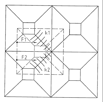
In any position of engagement of the two embossing rollers,
the embossed material is forced around structural edges Kl,
K2. This produces a paper tension which generates the
forces Fl and F2 on the idle roller, thereby contributing to
a displacement of this embossing roller from the instable
position according to FIG. 6 to the stable position of
maximum penetration according to FIGs. 4 and 5. As
mentioned, a considerable force is required in order to
displace the rollers out of the mutually stabilized position
of maximum penetration in the axial or in the
circumferential direction. A safe and stable driving of the
idle roller with a constant mutual tooth position in the
corresponding range of engagement is therefore ensured. At
the same time, an optimal embossing, especially also of
paper foils, is ensured. In the initial position of
engagement, the teeth could also mutually contact the flanks
in the axial direction, in which case the stable position of
engagement would be attained by a relative displacement in
the circumferential direction.
FIGs. 7 and 8 schematically show a comparison of the
embossing process in the position of the invention (FIG. 7)
and in the conventional tooth position (FIG. 8). In both
figures, the points of the teeth of one roller are indicated
by triangles and those of the other roller by circles. The
dotted lines are the relevant breaking lines, and it appears
that the embossing length in the tooth position of the
invention is substantially longer than in the conventional
tooth position while the foil nerves are not only folded
free of tension but also in symmetrical diagonal directions
additionally.
For a reliable operation, however, certain minimal
conditions must be fulfilled as well. Thus, in the
embossing procedure of the invention according to FIG. 7,
CA 02256325 1998-12-17
- 7 -
the metallized paper can provide a dynamic compensation of a
certain pitch error AT of the two embossing rollers due to
its elasticity. In other words, an embossing according to
the invention is no longer possible if the pitch difference
AT is greater than a certain self-centering factor. In any
case, the embossing pattern will deteriorate if the self-
centering resp. -synchronization is not ensured. The terms
of the following relationships are
T1 = radial pitch of the first roller
T2 = radial pitch of the second roller
AT = pitch difference
THT = theoretical radial pitch (nominal pitch)
SZF = self-centering factor
EF = empirically determined factor = 98.75.
SZF = EHT AT = T1 - T2 SZF >_ I OT
F
In a numerical example, this means:
Tl = 0.402
T2 = 0.399
THT = 0.400
AT = 0.402 - 0.399 = 0.003
SZF = 0.400 = 0.00405
98.75
0.00405 _ 0.003,
which means that the self-centering effect is ensured. The
preceding dimensions are all in mm.
The described preferred embodiment offers simplicity,
reliability, long lifetimes of the rollers, a high quality
of the embossing independently of the foil material, and
simple operation. In this embodiment, it is advantageous to
CA 02256325 2006-11-20
23444-381
8
use the described tooth shape which allows the dynamic
displacement into the preferred stable mutual position of
the sets of teeth. Alternative embodiments are also
possible, however.
The rollers may be provided with teeth of different heights
or of the same height, i.e. the pitches have to correspond,
of course, but the amount of flattening may vary.
Preferably, in the case of different heights of the teeth,
the idle, i.e. the undriven roller is provided with the
lower teeth. It will be exposed to a slightly greater wear,
but it is easier to exchange than the driven roller.
The rollers may also comprise means for a preliminary or
coarse orientation, e.g. coarse sets of teeth at the edges
resp. on the sides of the rollers which engage in each other
at the start and provide a coarse orientation of the
rollers, thus contributing to a correct engagement and the
subsequent transfer of the rollers to their stable
positions. These orienting means have to have enough play
in order to allow a free mutual displacement of the rollers
to the stable position.
It is also possible to lock the mutual roller positions as
soon as the stable position of engagement is attained and
thus to exclude any risk that the rollers might jump from a
stable position to a different one. For example, as soon as
the stable position is attained, the axial position of the
idle roller might be locked by clamping the axially
displaceable roller axle, and a previously uncoupled play-
free gear could be connected between the two rollers.
Ultimately, the rollers could also be mutually positioned by
play-free gears or in such a disposition that a mutual
engagement in the sense of the invention is predetermined
from the start.