Note: Descriptions are shown in the official language in which they were submitted.
CA 02259171 1998-12-18
WO 98100745 PCT/CA97J00467
MICROSCOPE SLIDE WITH REMOVABLE LAYER AND METHOD
FIELD OF THE INVENTION
This invention relates generally to an apparatus and
method useful in the field of microscopy. More
S particularly, the invention relates to a slide having a
removable surface layer with at least one exposed region
on the slide such that when the surface layer is removed,
material to be examined remains on the slide and is
confined to the exposed regions) of the slide.
BACKGROUND OF THE INVENTION
Biological cells and other materials are routinely
mounted on slides and examined with the aid of a
microscope. Stains are usually employed in some manner
to enhance the visibility of cells or cell components
such as specific proteins, amino acids or DNA. In
general these sample assessments seek to locate and
identify cells with abnormal characteristics. Diagnosis
of biological samples is typically accomplished by human
visual identification, although machine vision alone or
machines which provide additional quantitative
measurements are gaining acceptance to assist with what
is often an arduous task.
The ability to efficiently examine and diagnose
samples on slides is influenced by a large number of
factors including the following:
(i) Restricting material placement on the slide;
(ii) Treating the sample to achieve optimal viewing;
(iii) Observing all or the vast majority of material
on the slide.
SUBSTITUTE SHEET (RULE 26~
CA 02259171 1998-12-18
WO 98/00745 PCT/CA97/00467
- 2 - -
The advantages of restricting sample material
placement on a slide include but are not limited to:
(i) material is easy to locate;
(ii) material is limited to regions appropriate for best
observation (e.g. away from edges of the slide and
coverglass);
(iii) the amount of material or area covered by material
is limited to facilitate quick and rigorous observation
and analysis.
If sample material is restricted to specific regions
of the slide, it is much easier to establish with some
confidence that all the material present was viewed by
either human or machine vision or both. In some
applications (e.g. clinical use as a medical device) the
ability to make these direct comparisons may be essential
in obtaining appropriate device approvals and/or
establishing the required confidence to broadly adopt use
of the device within medical practice. Experts in the
field of applied machine vision will have a full
appreciation of these factors.
In conventional use, material for examination under
a microscope is routinely deposited on a microscope slide
by smearing, blotting or some method of sedimentation
from fluid suspensions, often using a centrifuge.
Conventional methods of making slides recognize the need
to (i) increase the adherence of material to the slide;
(ii) increase the desired composition of the sample (e. g.
the desired number and or type of cells present); (iii)
improve the presentation of material (e. g. spread
material out, ideally in a single focal plane, while
reducing obscuration due to overlapping material); (iv)
improve the consistency of the presentation of material;
(iv) capture material on another device and then bind
this device or otherwise transfer the desired material to
r
CA 02259171 1998-12-18
- WO 98/00745 PCT/CA97/00467
- 3 -
the slide; (v) restrict material for viewing to permanent
wells or defined regions of the slide; and (vi) ensure
that the sample material (e.g. cells) deposited on the
slide is a true and representative sample (e.g. of the
organ or tissue site) for the intended use.
In general, material deposited using conventional
methods may by intent or by accidental contact, appear
anywhere on the surface of the slide. Although some
sample deposition methods, such as blotting material
to previously captured on a circular filter, do provide some
control over the region, these methods do not restrict
the placement of sample material. Accidental transfer of
material beyond the original region may easily occur as
slides undergo subsequent handling, staining or other
common sample processing steps.
Restricting the placement of material on a slide is
not fully addressed in the prior art.
United States Patent No. 3,551,023 to Brackett
discloses a laminated specimen holder which is used for
tissue samples and sandwiches material between two thin
films, however, material does not contact the slide
surface and this invention specifically suggests not
using a microscope slide for this purpose.
Goldsmith in U.S Patent No. 4,190,314 acknowledges
that observation of all the material on the slide is
necessary to detect cancerous cells, if present, even in
very low numbers. Goldsmith provided a series of grid
lines to help direct user observation along defined grid
paths. This method suffers from the disadvantage that
the lines can obscure some subtle cellular details and
has limited scope because observations on an individual
sample often require the use of more than one objective
lens.
CA 02259171 1998-12-18
WO 98/00745 PCT/CA97/00467
- 4 -
Current microscope based system design may use
'electronic grid lines' providing users with slide
tracking information as users perform slide scanning. A
pictorial or other indicator related to the scanning
process is provided by the microscope system and may be
accompanied by 'electronic marking' (remembering x,y
stage coordinates and perhaps information on the
objective lens and focus position) of important areas for
more detailed or subsequent review. Alternatively,
microscope systems may employ a computer driven stage
under full or interactive user control to scan the slide
surface in a pre-defined manner, however, it is still
necessary to know the boundaries of the sample region so
that a pre-defined pattern over the region can be
established with confidence.
Even if the region boundaries are known and all
regions of the slide are visited, abnormal cells may
still fail to be observed due to overlapping material or
optical changes which may occur at the edges of the slide
and coverglass. The problem of overlapping material is
recognized in the field and techniques have been
developed to reduce this in a number of ways. One
approach is to prepare a uniform thin layer of sample
material from a fluid suspension utilizing density
centrifugation, centrifical methods or otherwise blotting
cells first captured on a filter.
U.S. Patent 5,170,285 to Shibasaki describes a semi-
transparent slide that scatters light emitted from a
microscope to optically eliminate the outline of pores of
a filter medium included in the configuration. The slide
surface is non-removable and the implementation does not
restrict the placement of specimen material.
Machine vision systems, some of which employ neural
networks, along with others that make measurements on the
1
CA 02259171 1998-12-18
WO 98100?45 PCT/CA9?100467
- 5 -
spatial distribution of DNA in cell nuclei have
performance that depends on properly observing all, or
the vast majority of cells or cellular material, present
on the slide.
The need to observe all cells for maximum detection
sensitivity has been recognized, and is true for both
humans and machines. Achieving this objective is
becoming more important as machine vision gains
acceptance in both interactive and automated roles in
sample screening. Even in cases where adequate machine
performance is achieved by looking at a subset of the
cells present, increased statistical accuracy and higher
confidence is achieved by observing all, or the vast
majority of cells present. A number of barriers serve to
limit the acceptance of machines for cell analysis. Some
of these include user acceptance based on performance,
and confidence. In addition, substantiating performance
claims by clinical trials is also necessary for medical
regulatory approvals in many countries. For machine
vision to be effectively employed, in most instances it
is desirable to know where the boundaries of the
regions) of interest are, restrict the size of the
regions) to practical dimensions commensurate with the
technology and time available for analysis, restrict
material to areas with consistent optical properties and
to provide confidence that material is not present on
areas beyond the desired region(s). The ability to limit
the placement of material to specific regions on a slide
means it is much easier to establish with some confidence
that all the material present will be viewed using
machine vision.
In many applications, including but not limited to
clinical samples, the material present on the slide
serves as a permanent and enforceable record.
Developments in many instances strive to ensure that
.. ~ m: w .: : :.~ ~ G 'J~; : "o : ,~.~ : (::w V~
CA 02259171 1998-12-18 ~ ~'~l~k~"'1 ~l.-. +.t,a Hu _,~~,~;yq"~.~a,:pi!
- 6 -
material to be examined is a true and repre3entative
sample of the mater~.al of interest (e. g. organ or tisau~e
site). In the case of diagnostic medicine, few
ursobaerved or incorrectly identified cells ef
significance rnay alter tfie interpretat~.on or, in cases of
error, may allow disease to go untreated, exposing the
tenting laboratory to significant risk and perhaps
foaming the basis of a litigious process. Unobserved
cells may result Pram overlapping rnsterial, non-uniform,
large amounts or wide dispersion of material. rt may be
difficult to consistently observe every field o.f the
slide when the region of interest is large or when
mate?~ial i9 present in areas which are net best for
obserJation (e. g. near edges of the slide or coverglass
Where optycal properties ;nay vary markedly).
SUMMA..RY OF THE INV~NT'ION
In view of the foregoing, there is a need for a
microscope sl~.de arrangement that addresses the
limitations of the prior art, particularly with respect
tc the desired feature of restricting material. placement
on the slide to specif is regions.
Applicant has developed a elide and a nethod far
rnakirg a slide in which the material deposited on the
slide is easily and reliably confined to a specific
region.
Accordingly, in a first aspect the present invention
provides a slide for depositing material far observation
under a microscope comprising:
a mounting surface to rece~.ve material for
3G obBervation;
CA 02259171 2001-04-25
_ 7 _
a removable layer on the mounting surface formed
with at least one opening in the removable layer to
define at least one exposed region on the mounting
surface, the removable layer and the at least one opening
being adapted to receive material for observation such
that detachment of the layer from the mounting surface
removes material deposited on the layer and the mounting
surface retains material to be observed only in the at
least one exposed region on the mounting surface.
In a further aspect, the present invention provides
a method for preparing a microscope slide having a
mounting surface on which material is deposited and that
includes a removable layer formed with at least one
opening therein defining at least one exposed region on
the mounting surface comprising the steps of:
processing and fixing material to be observed on the
mounting surface of the slide over the removable layer
and the opening therein; and
removing the removable layer from the mounting
surface to create at least one region on the mounting
surface that retains material to be observed within set
boundaries defined by the at least one opening.
In a still further aspect, the present invention
provides a method for preparing a microscope slide having
a mounting surface on which material is deposited
comprising the steps of:
applying a removable layer formed with at least one
opening therein to the slide to define at least one
exposed region on the mounting surface of the slide;
....., ~..: ..: ' ;~ its : y:3:.3 J : (;o;i ry. C:i=Uh(V ~ .1 :~n . _ +4.)
f;:i ~>:3;3f1~1-tn~;~: rll:s
CA 02259171 1998-12-18
_ g
processing and fixing material to be obsex-~red on the
mounting surface of the slide over the removable layer
and the opening therein; and
removing the removable layer from the mounting
surface to create at least one region on the mounting
surface that retains material to be observed within set
boundaries defined by the at least one opening.
The apparatus and method of the present invention
provide a elide having the following desirable
properties:
(i) material is restricted to a defined region at the
slide
(ii) the shape and dimensions of the defined region are
controlled, and
(iii) multiple regions can be provided on the slide.
The foregainglprogerties provide,increased confidence
that ;material on the slide does not appear beyond the
desired regions) of the slide.
The slide and method of the present invention
provide the following potential advantages:
... The device can be used with many existing cell
deposition methods including:
Smears, touch preps, blotting and thin layer
techniques.
The device allows some sample treatment steps prior
to removal of the surface layer potentially reducing
stain ox ether requirements.
n~ v . wn.v : t t'A hil~E::~'Cail.:~~ tW : ~~~~ _ ~_ ;~~ : _~:~ : q.y : E;~,p
W. Gf~t~hC~ 1 A S~1'. -~ +~EJ tl;~ '?,ia:J4~~i~(~~ : ~ I 9
CA 02259171 1998-12-18
- 8a -
The device acts as a temporary reactifln cY.arn~er to
facilitate sample treatment prior to the removal of the
surface layer.
The device allows material to be restricted to
regions of convenient shapes and sizes.
CA 02259171 1998-12-18
WO 98!00745 PCT/CA97/00467
_ 9 _ _
The device protects from the accidental placement of
sample material outside of the desired regions?.
The device increases productivity by restricting
material to a designated area of the slide for faster
locating by both human and machine vision.
The device serves an active role in cell preparation
by carrying stain or influencing the sample before it
contacts the region of interest.
The device is used to restrict material away from
edges of the slide or coverglass to reduce or eliminate
these optical interferences.
The device makes it practical to observe all or the
vast majority of material present on the slide by
restricting the amount, area and location available for
material.
The device provides increased confidence that
material does not appear outside of the, restricted
region.
The device itself facilitates the production of a
disperse sample for some uses by providing a plurality of
small regions.
The device makes it practical to have several of the
same or different samples on the same slide. These
sample regions may or may not be treated in the same
manner.
CA 02259171 1998-12-18
WO 98/00745 PCT/CA97/00467
- 10 - -
BRIEF DESCRIPTION OF THE DRAWINGS
Aspects of the present invention are illustrated,
merely by way of example, in the accompanying drawings in
which:
Figure 1 is a perspective view of a preferred
embodiment of a slide according to the present invention
with a removable surface layer having at least one
exposed region;
Figure 2 shows a perspective view of the slide with
the surface layer removed;
Figure 3 is a perspective view of an alternative
embodiment of a slide according to the present invention;
Figure 4 shows a perspective view of another slide
according to the present invention;
Figure 5 is a perspective view of a further slide
embodiment having a plurality of separate removable
layers that are removable independently of each other;
Figure 6 is a perspective view of another slide
embodiment having a removable layer formed with a
plurality of small openings to assist in dispersion of
sample material; and
Figure 7 shows a slide according to the present
invention supporting a cuvette of sample material sealed
to the removable layer which acts as a gasket over the
opening in the layer.
CA 02259171 1998-12-18
WO 98/00745 PCT/CA97/00467
- 11 - -
DESCRIPTION OF THE PREFERRED EMBODIMENTS
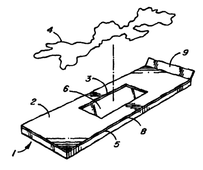
Referring to Figure 1, there is shown a microscope
slide 1 for observing material under a microscope
according to a preferred embodiment of the present
invention. The slide comprises a mounting surface 5 in
the form of a conventional glass slide having a removable
surface layer 2 applied thereto. Removable layer 2 is
formed with an opening 3 to define an exposed region 6 on
mounting surface 5 for retaining material 4 to be
observed.
In use, material 4 to be observed under a microscope
is deposited in an appropriate manner on the slide of the
present invention in the general area of opening 3 in
removable layer 2. The sample material is processed and
fixed on the mounting surface of the slide over the
removable layer and the opening therein. Removable layer
2 is then detached from mounting surface 5 by pulling on
tab 9. As a consequence of removing layer 2, sample
material 4 to be observed remains on mounting surface 5
only in the region 6 defined by opening 3 to create a
region having definite boundaries. The area of the slide
to be examined in detail extends beyond the border of
exposed region 6 as indicated by lines a-b-c-d in Figure
2. A region of desired dimensions can be selected to
best suit a particular application. Areas of the slide
which may be difficult to observe (e.g. edges of the
slide or coverglass which could have undesirable optical
properties) can be avoided.
Figure 4 illustrates an alternative embodiment of
the slide of the present invention in which removable
layer 2 is formed with a pair of openings 3a and 3b. The
number and dimensions of such openings can be selected as
desired. A plurality of openings in layer 2 provide for
a slide having a plurality of discrete, spaced openings
CA 02259171 1998-12-18
WO 98/00745 PCT/CA97/00467
- 12 - -
to define a plurality of exposed regions on the mounting
surface when the removable layer is detached.
In a further embodiment shown in Figure 5, removable
layer 2 is divided into multiple portions 14. Each
portion is detachable from the mounting layer
independently of the other portions and is formed with at
least one opening 3. This arrangement allows different
sample treatment steps such as staining to be carried out
on the samples and potentially reduces reagent
requirements and hence reagent costs by virtue of the
fact that the entire slide does not need to be treated
only the region defined by each opening 3. Opening 3
also acts as a well to receive and contain stains or
other reagents to the region of the sample material.
Individual and independent treatment, particularly
by staining, of each opening 3 also has the advantage
that cross-contamination of slides and samples is
avoided. Conventional slides are often treated by
immersing batches of slides in a bath of reagent. The
bath of shared or reused reagent can lead to cross-
contamination of slides as material is transferred from a
first slide to the bath and then on to a second slide.
Figure 6 illustrates a further embodiment in which
removable layer 2 is formed with a multitude of
microscopic openings as shown in enlarged view 10. When
cellular material is deposited on the slide and layer 2
removed, the microscopic openings will act to create a
dispersed array of cellular specimens on the slide.
In all embodiments, removable layer 2 preferably
comprises a sheet of flexible material having an adhesive
surface 8 to removably attach the removable layer to
mounting surface 5. The sheet of flexible material is
formed with a non-adhesive gripping tab 9 to facilitate
CA 02259171 1998-12-18
WO 98100745 PCTlCA97100467
- 13 - -
removal from the mounting surface. Tab 9 is preferably
an overlapping end of the removable Layer 2 (with the
exposed adhesive covered) to provide a simple, consistent
gripping point to peel away the removable layer like a
tape strip.
Several options were evaluated to determine an
effective removable layer 5. Evaporation methods were
tested and demonstrated that thin layers could be created
on the surface of the slide, exposing a region, however,
these lacked some of the desired properties outlined
above and required a drying step. Advances in materials
may make these viable options in the future.
It is preferable that the removable Layer is formed
from materials having one or more of the following
properties:
(i) the material is relatively easy to remove from the
mounting layer,
(ii) possible damage to the removable layer can be
observed
(iii) the removable layer is resistant to drying and is
resilient to a wide range of environmental factors such
as heat and moisture
(iv) the removable layer can withstand a wide range of
routine sample treatment steps which may be employed
before removing the layer
(v) the slide is not damaged by the removal of the
removable layer
(vi} removal of the removable layer has little or no
effect on the sample material left behind in the exposed
region
(vii) removing the removable layer leaves little or no
residue on mounting surface 5.
CA 02259171 1998-12-18
WO 98100745 PCTICA97I00467
- 14 - -
The adhesive material for removable layer 2 is
preferably selected from a distinct category of adhesives
often referred to as "pressure-sensitive". These
adhesives are characterized by what has been termed a
"four-fold balance" of adhesion, cohesion, stretchiness
and elasticity. The pressure sensitive adhesive should
satisfy the requirements stated above which include no or
little residue transfer, resistance to drying, stability
over a range of temperatures and resistance to some
sample processing steps.
A wide range of suitable pressure-sensitive
adhesives are available. Some common types include
synthetic rubber (providing controlled properties)
tackified with some type of resinous material also known
as rubber-resin adhesive. These can be formulated so as
not to permit adhesion buildup. In general, there are
advantages to using newer wholly synthetic pressure-
sensitive adhesives since their behaviour is predictable
and can be controlled making them more suitable for
manufactured products. Silver in United States Patent
No. 3,922,464 issued November 25, 1975 describes an
adhesive sheet material that employs a pressure-sensitive
adhesive that make it removable from a wide variety of
surfaces. The material comprises a self-sustaining
backing which is coated with a stable viscous copolymer
latex formed from monomers of (1) major amounts of alkyl
acrylates (2) minor amounts of certain emulsifier
monomers and (3) if desired, minor amounts of
zwitterionic monomers. The water is evaporated from the
latex to leave a tacky pressure-sensitive adhesive. 3M
Corporation and others have a wide range of sheet-like
products which employ pressure-sensitive adhesives which
are suitable to implement the basic removable layer of
the present invention.
CA 02259171 1998-12-18
WO 98/00745 PCT/CA97/00467
- 15 - -
Removable layer 2 is preferably opaque so that it is
easy to observe its presence, its removal and any
damage. In addition, this surface layer can be color
coded to identify slides for specific applications with
potentially different surface layer compositions.
The removable layer described preferably has some
inherent elastic properties owing to the material of the
layer, its thickness and the adhesive on the self
adhesive side.
The removable surface layer described can function
as a gasket as illustrated in Figure 7. Cells in fluid
suspension are often deposited onto the surface of a
microscope slide via sedimentation or under increased
gravitational force achieved by centrifuging. Figure 7
shows an open sample tube or cuvette 11 pressed against
removable layer 2 about opening 3 to form a seal 12. For
use in such an application, removable layer 2 is formed
with additional adhesives or includes a groove cut into
layer 2 to receive and seal the edges of the sample tube
11. Alternatively, layer 2 can include a rubber-like
coating of appropriate thickness to receive the sample
tube. The foregoing arrangements eliminates the need for
a separate gasket that is necessary with conventional
slides.
In addition to the above beneficial properties,
removable layer 2 can be designed and selected to have
other useful properties. Three examples of these
properties are as follows:
(i) The removable layer can include on or as a part of
the layer a substance selected to interact with the
material to be observed. The removable layer can be
coated with a substance which interacts with the sample
material in a desired way, perhaps staining or
io ;J~ : ~a : 4 ;l
(J:m W. (a:,EWEJ I ~1 Sy,
CA 02259171 1998-12-18
+~l : t t S,l :.;J;J:J~1'I E::~ . ,I L
- 16 -
selectively effecting the concentration of the material.
that; Eventually contacts the exposed area of the slide.
To expand on this theme witr: a specific example, Figure 3
illustrates a slide having a removable cover layer coated
with a protein which preferentially binds to one type of
cell. The protein is employed ds a component of the
removable layer 2 to remove some undesired cells. Sample
material containing a mixed population o~ cells A and F3
(e.g. maternal blood containing fetal cells) at
concentrations of 99B cells per tho~.zsand cells and 2
cells per thousand, respectively, is applied to the
removable ei:rface 2. The s?ide is C,iltea allowing the
sample ttEaterial to flow to opening 3 in the direction of
arrow 13 over the protein, selectively binding and
removing some of the undesired material or cells while
unbound material continues to move toward opening 3. The
resulting concentration of the desired cells (e. g, fetal
cells) ie higher (e.g. 20 cells per thousand) in Lhe
resulting sample material depoc~ited on mounting surface 5
within opening 's.
(ii) The removable surface layer is desigaed such that it
can also function as a gasket allowing a seal to be made
to facilitate the centrifical deposition of sample
material on the desired regions) of the slide.
(iii) The slide of Figure 4 is useful for preparing and
treating the same material differently on the same slide.
Sample material (e.g. cells) in exposed regions 3a and 3b
(FIGURE 4) is first t:~c~eated in some manner (e.g. DNA
stair_ed). Region 3b is then sealed with a temporary
covering material 7, allowing an additional processing
step (e. g. Pap staining) to be applied to the sample
material in region 3a. The temporary covering material
is then removed and the samp3es analyzed.
CA 02259171 1998-12-18
WO 98/00745 PCT/CA97/00467
_ 1~ _ _
Although the present invention has been described in
some detail by way of example for purposes of clarity and
understanding, it will be apparent that certain changes
and modifications may be practised within the scope of
the appended claims.