Note: Descriptions are shown in the official language in which they were submitted.
CA 02260491 1999-O1-28
METHOD FOR TRANSMITTING VSB DIGITAL TV WITH CARRIER
FREQUENCY NEAR CO-CHANNEL NTSC AUDIO CARRIER FREQUENCY
This application is filed under 35 U.S.C. 111 (a) claiming pursuant to 35
U.S.C. 119(e)(1) benefit of the filing date of provisional application serial
No.
60/075,424 filed February 20, 1998, pursuant to 35 U.S.C. 111(b).
The present invention generally relates to television signal transmission
systems and particularly concerns a method of transmitting a vestigial
sideband
(VSB) digital television signal having reduced susceptibility to NTSC co-
channel
interference.
BACKGROUND OF THE INVENTION
The specification and drawing of U. S. patent No. 5,087,975 issued 11
February 1992 to R. W. Citta et alii and entitled VSB HDTV TRANSMISSION
SYSTEM WITH REDUCED NTSC CO-CHANNEL INTERFERENCE are
incorporated herein by reference. Citta et alii describe a television signal
transmission signal for broadcast television comprising a suppressed carrier,
a VSB
signal having respective Nyquist slopes at the lower- and upper-frequency
edges of a
television channel with 6-MHz bandwidth, the center frequency of the Nyquist
slope
at the lower-frequency edge of the channel being substantially coincident with
the
frequency of the suppressed carrier, and a pilot signal in quadrature relation
with the
suppressed carrier. The television signal transmission signal is susceptible
to co-
channel interference from NTSC television signal with a video carrier 1.25 MHz
above the lower-frequency edge of the channel, a color subcarrier 3.58 MHz
above
the video carrier in frequency, and an audio carrier 0.25 MHz below the upper-
frequency edge of the channel. The suppressed carrier is modulated by an N-
level
digitally encoded signal having a sample rate fs substantially equal to three
times the
NTSC color subcarrier frequency, with the frequency of the suppressed carrier
being
closer to the lower-frequency edge of the channel than the co-channel NTSC
picture
carrier by an amount equal to about fs /12. The received signal is demodulated
by a
synchronous detector in response to the received pilot signal and interfering
NTSC
CA 02260491 1999-O1-28
beat components are attenuated by a linear filter having notches at fs /12, at
5 fs /12
and at fs /2.
A Digital Television Standard published 16 September 1995 by the Advanced
Television Systems Committee (ATSC) specifies VSB signals for transmitting
digital
television (DTV) signals in 6-MHz-bandwidth television channels such as those
currently used in over-the-air broadcasting of National Television System
Committee
(NTSC) analog television signals within the United States. These VSB signals
differ
from those described by Citta et alii in that each uses a pilot signal in
phase with its
suppressed carrier, rather than in quadrature therewith. These VSB signals
each
comprise a vestigial sideband near the lower upper-frequency edge of the
television
broadcast channel and a full sideband extending upward in frequency therefrom
to the
upper-frequency edge of the channel.
SUMMARY OF THE INVENTION
The invention is directed to the transmitting of a television signal
transmission
signal comprising a suppressed carrier, a pilot signal in phase with the
suppressed
carrier, and a VSB signal having its vestigial sideband near the upper-
frequency edge
of a television broadcast channel and its full sideband near the lower-
frequency edge
of the channel. The suppressed carrier is modulated by an N-level digitally
encoded
signal having a sample rate fs substantially equal to three times the NTSC
color
subcarrier frequency, with the frequency of the suppressed carrier being
further from
the lower-frequency edge of the channel than the co-channel NTSC picture
carrier by
an amount equal to about Sfs /12. The received signal can be demodulated by a
synchronous detector in response to the received pilot signal and interfering
NTSC
beat components are attenuated by a linear filter having notches at fS /12, at
fs /4 and at
fs /12.
BRIEF DESCRIPTION OF THE DRAWINGS
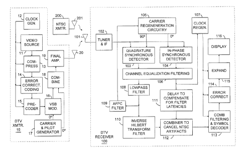
FIGURE 1 is a block diagram of a television signal transmission system
constructed in accordance with the invention.
2
CA 02260491 1999-O1-28
FIGURE 2 is a graph illustrating the spectrum of a 6 MHz DTV television
channel when DTV transmissions are made in accordance with the invention.
FIGURE 3 is a graph illustrating the response of a DTV receiver to co-channel
DTV and NTSC transmissions, when the DTV transmissions are made in accordance
with the invention.
FIGURE 4 is a block diagram of an inverse Hilbert transform filter useful in
the DTV receiver of FIGURE 1.
DETAILED DESCRIPTION
The problem addressed by the present invention is generally illustrated in the
block diagram of FIGURE 1. A DTV transmitter, designated generally by
reference
numeral 10, broadcasts a DTV encoded signal over a selected 6-MHz-wide
television
channel for reception and reproduction by a corresponding DTV receiver 100
tuned to
the selected channel. At the same time, an NTSC transmitter 200 broadcasts an
NTSC encoded signal over the same channel in a nearby television service area.
Depending on various factors including its physical location, the DTV receiver
100
may thus receive an undesired interfering component of considerable strength
from a
transmission antenna 201 of the NTSC transmitter 200 in addition to the
desired
signal from a transmission antenna 20 of the DTV transmitter 10. Since the
undesired
interfering signal is transmitted on the same channel as the desired DTV
signal, it is
commonly referred to as "co-channel interference". The co-channel interfering
signal
in the DTV receiver especially poses a problem in the case where an all
digital DTV
transmission standard is employed. In particular, if the co-channel
interfering signal
is of sufficient strength to overwhelm the digital DTV signal in the receiver,
the
ability of the receiver to reproduce an image of any quality may be completely
compromised. Moreover, this impairment of the DTV receiver may arise quite
abruptly with variations in the strength of the interfering NTSC co-channel
signal.
This is in contrast to analog DTV transmission systems in which variations in
the
strength of the interfering NTSC co-channel signal cause gradual changes in
the
signal-to-noise performance of the receiver.
3
CA 02260491 1999-O1-28
As known, the spectrum of the interfering NTSC co-channel signal occupies a
6-MHz-wide television channel and includes a luma component, a chroma
component
and an audio component. The luma component has a bandwidth of about 4.2 MHz
and is modulated on a picture carrier spaced 1.25 MHz from one end of the
channel.
The chroma component, which has a bandwidth of about 1 MHz, is modulated on a
subcarrier spaced about 3.58 MHz from the picture carrier. The audio component
is
modulated on a carrier spaced 0.25 MHz from the other end of the channel
(i.e., 4.5
MHz from the picture carrier). Major contributors to co-channel interference
are the
relatively large NTSC picture carrier and sidebands thereof encoding sync
information and high-luma image components, color burst, chroma subcarrier
sidebands during high-chroma image components, and the FM audio carrier.
NTSC picture carrier peaks during sync intervals provide the highest energy
co-channel interference. When comb filtering is used to suppress NTSC co-
channel
interference, it is desirable for the comb filtering be designed for best
suppression of
artifacts of the NTSC video carrier and its 15,734 Hz sidebands. Chroma burst
has
only 20 % or less of the energy NTSC picture carrier peaks have during sync
intervals. Comb filtering can suppress artifacts of NTSC luma and chroma
signals
descriptive of large areas in the image. The errors introduced by artifacts of
NTSC
luma and chroma signals descriptive of moving edges in the image have to be
corrected using error correcting codes.
While constrained in amplitude to about 7-10% of video carrier peak
modulation, the FM audio carrier is of sustained amplitude. This makes it
difficult to
use error-correcting codes for correcting errors introduced by the FM audio
carrier.
The frequency and phase modulation of the NTSC audio carrier makes comb
filtering
using differential delay of more than a few symbol epochs impractical for
suppressing
artifacts of NTSC audio signal. The fact that modulation signals vary at audio
and
low supersonic rates provides enough correlation between samples only a few
symbol
epochs apart permits the 12-symbol-differential-delay comb filters used for
ATSC
signals to have some success in suppressing artifacts of NTSC audio signal.
4
CA 02260491 1999-O1-28
FIGURE 2 illustrates the spectrum of a DTV transmission channel according
to the present invention. The channel is 6 MHz wide, corresponding to an NTSC
transmission channel through which a VSB signal is transmitted as illustrated.
More
particularly, below a first breakpoint frequency f,bp no more than 353 kHz or
so from
the lower-frequency edge of the transmission channel, the transmission channel
exhibits an amplitude response roll-off 22. The VSB signal has a substantially
flat
amplitude response portion 24 extending from the first breakpoint frequency
f~bP to a
second breakpoint frequency fZbp somewhat less than 5,643 kHz or so from the
lower-frequency edge of the transmission channel. The picture carrier
frequency fp;~
of a co-channel interfering NTSC signal 1,250,00 Hz from the lower-frequency
edge
of the transmission channel, is within the frequency range comprehended by
this
substantially flat amplitude response portion 24. The chroma subcarrier fs~ of
a
co-channel interfering NTSC signal 4,829,545.5 Hz from the lower-frequency
edge of
the transmission channel, is preferably within this frequency range as well.
Between
the second breakpoint frequency f~bP and a third breakpoint frequency f36P the
transmission channel exhibits a roll-off 26 in amplitude response to one-half
the
amplitude response through the substantially flat amplitude response portion
24,
which halved amplitude response extends as another substantially flat
amplitude
response portion 28 from the third breakpoint frequency f3bP to a fourth
breakpoint
frequency f~bP. The halving is in the degree of modulation, not in energy.
The suppressed carrier frequency f~ and pilot signal frequency f~, of the DTV
signal are both at a frequency slightly less than 5,734 kHz from the lower-
frequency
edge of the transmission channel to position them slightly less than 285 times
NTSC
horizontal scan frequency fh above the NTSC picture carrier frequency fP;,~.
This is
done to best accommodate comb filtering in the receiver 100 to suppress
artifacts of
the picture carrier frequency fP;~ and chroma subcarrier fs~ of a co-channel
interfering
NTSC signal. The suppressed carrier frequency f~ and pilot signal frequency fP
of the
DTV signal are at the center of the frequency range comprehended by the
substantially flat amplitude response portion 28. The substantially flat
amplitude
response portion 28 extends to include frequency-modulated audio carrier fa of
a
co-channel interfering NTSC signal and its frequency-modulation sidebands of
CA 02260491 1999-O1-28
significant energy. Accordingly, the fourth breakpoint frequency f4bP is
positioned
5,825,000 Hz or slightly more from the lower-frequency edge of the
transmission
channel. Above the fourth breakpoint frequency f.~bP the transmission channel
exhibits
an amplitude response roll-off 30. The third breakpoint frequency f36P is as
much
below the suppressed carrier frequency f~ in frequency as the fourth
breakpoint
frequency f46P is above. The roll-off 26 in amplitude response between the
second
breakpoint frequency f2bP and third breakpoint frequency f3bp is designed to
complement the roll-off 30 in amplitude response, so when the television
signal
transmission signal is demodulated in the receiver 100 the baseband DTV signal
has a
flat amplitude response from zero frequency up to a frequency half the Nyquist
sampling frequency fs - i. e., up to 5,381,118.9 Hz. The transmitter phase
response is
maintained linear through the frequency range extending from less than 353 kHz
or so
from the lower-frequency edge of the transmission channel to the frequency at
which
the roll-off 30 in amplitude response has reduced energy at high frequencies
to
negligible level, so that absent multi-path phenomena there will be uniformity
of
group delay in DTV signal components demodulated by the receiver 100.
As pointed out in U. S. patent No. 5,087,975, the Nyquist bandwidth fs/2 of
the channel can be thought of as being divided into six equal parts, with the
interval
between the co-channel NTSC picture carrier fp;X and color subcarrier fs~
corresponding to four of these six parts. I. e., fs~ - fP;,~ _ (4/6) (fs/2) _
(4/ 12) fs =
(1/3)fs. The Nyquist symbol frequency is initially presumed to be three times
(fs~ - fp;;~) = 3 * 3,579,545.5 Hz =10,738,636.4 Hz.
In contrast to what is shown in U. S. patent No. 5,087,975, the interval
between the suppressed carrier frequency f~ of the DTV signal and the co-
channel
NTSC picture carrier fp;,~ corresponds to five of the six parts, rather than
just one of
these six parts, and the interval between the suppressed carrier frequency f~
of the
DTV signal and the co-channel NTSC color subcarrier fs~ corresponds to only
one of
the six parts, rather than five of these six parts. I. e., f~ - fP;~ _ (5/6)
(fs/2) _ (5/12) fs,
and f~ - fs~ _ (1/6) (fs/2) _ (1/12) fs.
CA 02260491 1999-O1-28
FIGURE 3 depicts the baseband response of DTV receiver 100. As illustrated
in this figure, the nominal response 40 of the DTV receiver is substantially
flat across
the channel, and accommodates the Nyquist bandwidth of fs/2 without
attenuation.
The baseband DTV signal is preferably produced by an "in-phase" synchronous
detector in response to a regenerated carrier having a frequency and phase
corresponding to the suppressed DTV carrier f~. In the presence of an NTSC
co-channel signal, detection in response to the regenerated carrier may also
provide a
pair of interfering beat signals at frequencies corresponding substantially to
fs/12 and
Sfs/12 arising respectively from the chroma subcarrier and the video carrier
of
co-channel NTSC interference: The interfering beat signals are represented in
FIGURE 3 by reference numerals 42 and 44, respectively. Another beat signal 46
slightly above zero frequency appears in the "in-phase" synchronous detector
response as an artifact of the NTSC FM audio carrier. A comb filter that
additively
combines baseband DTV signals having appropriate differential delay has a
response
50 with nulls 52, 54 and 56 in its response. The null 54 is near mid-channel
and
reduces mid-channel ringing response to impulse noise. The beat signals 42 and
44
that are the artifacts of the chroma subcarrier and the video carrier of co-
channel
NTSC interference are suppressed by the nulls 52 and 56 in the comb filter
response
50. As will be explained in further detail hereinafter, receiver 100 includes
a comb
filter having the response 50, for reducing the effect of the co-channel
interference
beats.
The ATSC Digital Television Standard makes the symbol rate fs 684 times the
NTSC horizontal scanning rate f,, to facilitate conversion between NTSC and
DTV
encoded signals, as suggested in U. S. patent No. 5,087,975. Accordingly, a
linear
comb filter additively combining samples differentially delayed by a six
symbol
interval provides a response including respective notches 52 and 56 at
frequencies
close to those of the beat signals 42 and 44. Since an NTSC horizontal scan
line has
exactly 684 symbols therein, a 6-symbol delay will be 114 times shorter than
an
NTSC scan line. An artifact having a frequency 114 * f,, will have one
complete cycle
in the 6-symbol period, so the comb filter additively combining samples
differentially
delayed by a six symbol interval has its notches at 1,793,706.3 Hz intervals.
7
CA 02260491 1999-O1-28
If the video carrier frequency fP;,~ were to fall exactly into the notch at
(5/2)
1,793,706.3 Hz, the DTV carrier frequency f~ would be (5/2) * 1,793,706.3 Hz
above
the video carrier frequency fP;X that is 1,250,000 Hz above the lower
frequency limit
of the channel. I. e., the DTV carrier frequency f~ would be 5,734,265.7 Hz
above the
lower frequency limit of the channel and 265,734.3 Hz below the upper
frequency
limit of the 6-MHz-wide channel. This would put the DTV signal carrier
frequency f~
at fh horizontal frequency offset from the NTSC audio carrier frequency fa, so
the
DTV signal carrier would be inaudible in an NTSC television signal receiver,
even if
the amplitude-modulation (Al~I) rejection of its sound circuitry were poor.
The
problem with doing this is that the first upper sideband of the stereophonic
pilot
carrier in the NTSC co-channel interfering signal will tend to affect the
acquisition of
DTV earner frequency in a DTV receiver if the DTV signal carrier fiequency f~
has
an f,, horizontal frequency offset from the NTSC audio carrier frequency fa.
It is preferable that the DTV carrier frequency f~ be slightly lower in
frequency
- e. g., 5,733,500 Hz above the lower frequency limit of the channel and
266,500 Hz
below the upper frequency limit of the 6-MHz-wide channel. This permits the
beat
between the DTV carrier frequency f~ and the first upper sideband of the
stereophonic
pilot carrier in the NTSC co-channel interfering signal to be about 765 Hz, so
it can
be rejected by a narrowband filter in the AFPC signal of the carrier
regeneration
circuitry. The DTV signal carrier will remain inaudible in an NTSC television
signal
receiver, even if the amplitude-modulation (AIVI) rejection of its sound
circuitry is
poor.
The DTV carrier frequency f~ can be placed at 57*fh below the frequency of
co-channel NTSC chroma subcarrier, which is 273,602 Hz below the upper
frequency
limit of the 6-MHz-wide channel. 'the DTV signal carrier may cause a 7867 Hz
tone
in an NTSC television signal receiver with stereophonic sound, if the
amplitude-modulation (AM) rejection of its sound circuitry is poor. The
acquisition
of DTV carrier frequency in a DTV receiver will be unaffected by co-channel
NTSC
stereophonic pilot signal, and chroma sidebands will be best suppressed. Co-
channel
NTSC video artifacts will be f,,/2 from the notch frequency of the comb filter
used for
rejecting NTSC artifacts. A comb filter employing 6-symbol differential delay
8
CA 02260491 1999-O1-28
provides -18dB rejection over a 71 kHz range including the notch frequency, so
rejection of co-channel NTSC video carrier artifacts will still be reasonably
good.
Then, too, co-channel NTSC video carrier artifacts can be cancelled by methods
other
than comb filtering since the double-sideband nature of the NTSC signal up to
750
kHz permits its separation from VSB DTV signal.
In accordance with the foregoing, and referring back to FIGURE l, the DTV
transmitter 10 comprises a video source 11 receiving a clock signal fs from a
clock
generator 12 to provide a digital video signal having a bandwidth of up to
about 37
MHz at a symbol rate of fs, where fs is nominally equal to 3fs~. The symbol
rate is
presumed to be 684 times the NTSC horizontal rate fh. By way of example, the
video
signal provided by source 11 comprises 787.5 progressively scanned lines per
frame,
720 of which represent active video, having a vertical repetition rate
corresponding to
the NTSC field rate and a horizontal repetition rate corresponding to three
times the
NTSC horizontal scanning rate. The video signal developed by source 11 is
applied
to a video compressor 13 which compresses the 37 MHz video signal sufficiently
to
allow for its transmission through a television channel of 6-MHz bandwidth.
The
compressed video signal can then be subjected to forward error correction
coding in
error correction coding (ECC) circuitry 14 with the ECC results being supplied
to
precoder circuitry 15. The ECC circuitry 14 comprises a Reed-Solomon coder
followed by a trellis coder and precoding is applied to selected symbols in
the trellis
coding result, in accordance with accepted practice under the ATSC Digital
Television Standard. The video compressor 13, the ECC circuitry 14 and the
precoder circuitry 1~ are operated in response to clock signal fs from clock
generator
12. The precoder circuitry 15 supplies partially pre-coded error-corrected
coding
results as modulating signal to a vestigial-sideband amplitude modulator 16.
Carrier
and pilot signal generation circuitry 17 supplies the VSB modulator 16 with a
carrier
signal having a nominal frequency fh horizontal frequency offset lower than
the
corresponding NTSC audio carrier frequency f~. Carrier and pilot signal
generation
circuitry 17 also supplies a pilot signal of frequency fp of the same
frequency and
phase as the carrier signal. The pilot signal is combined with the vestigial-
sideband
amplitude-modulation output signal from the VSB modulator 16 in a combining
9
CA 02260491 1999-O1-28
circuit 18 to form a signal for application to the final amplifier circuitry
19 used for
driving the transmission antenna 20. The video signal is transmitted as a
sequence of
N-level data samples, with the transmission preferably being effected in the
form of a
suppressed carrier, VSB signal as illustrated in FIGURE 2, with an in-phase
pilot
signal fp being combined therewith to facilitate regeneration of the carrier
in the DTV
receiver 100. The frequencies of the clock and carrier signals can, of course,
be
slightly adjusted from the nominal values previously described.
The DTV receiver 100 includes a reception antenna 101 tuner and IF stage
102 tuned to the 6 MHz television channel over which the DTV signal is
transmitted.
The tuned DTV signal, together with a co-channel NTSC signal broadcast on the
same channel by transmitter 200 in a nearby television service area, are
converted to
an intermediate frequency in stage 102 and supplied as input signal to an in-
phase
synchronous detector 103 and a quadrature-phase synchronous detector 104.
Carrier
regeneration circuitry 105 supplies in-phase regenerated carrier and
quadrature-phase
regenerated carrier to the in-phase synchronous detector 103 and to the
quadrature-phase synchronous detector 104, respectively. The baseband
responses of
the synchronous detectors 103 and 104 are supplied to channel equalization
filtering
106, which suppresses mufti-path responses to the DTV signal received from the
DTV
transmitter 10 and equalizes the channel to reduce intersymbol error. The
delayed
equalized in-phase synchronous detector 103 response from the channel
equalization
filtering 106 is supplied to clock regeneration circuitry 107 which
regenerates symbol
clock signal fs for use throughout the DTV receiver 100.
A lowpass filter 108 responds to the equalized quadrature-phase synchronous
detector 104 response from the channel equalization filtering 106 to generate
an error
signal indicative of any departure from correct frequency and phasing of the
in-phase
regenerated carrier and quadrature-phase regenerated carrier supplied to the
in-phase
synchronous detector 103 and to the quadrature-phase synchronous detector 104
by
the carrier regeneration circuitry 105. This error signal is further filtered
by an AFPC
filter 109 to be used as automatic frequency and phase control {AFPC) signal
for a
controlled oscillator included in the carrier regeneration circuitry 105.
CA 02260491 1999-O1-28
The equalized quadrature-phase synchronous detector 104 response from the
channel equalization filtering 106 contains response to all the single-
sideband
components of the VSB DTV signal which is the Hilbert transform of the
response to
all the single-sideband (SSB) components of the VSB DTV signal contained in
the
equalized in-phase synchronous detector 103 response from the channel
equalization
filtering 106. The response of the lowpass filter 108 to the equalized
quadrature-phase synchronous detector 104 response from the channel
equalization
filtering 106 is supplied to an inverse Hilbert transform filter 110, which
responds to
supply response to the lower-frequency SSB components of the VSB DTV signal
similar to the equalized in-phase synchronous detector 103 response to these
lower-frequency SSB components except for the latency or delay introduced by
the
inverse Hilbert transform filter 109. The equalized in-phase synchronous
detector 103
response from the channel equalization filtering 106 is delayed by a delay
line 111,
which compensates for the latencies or delays introduced by the filters 108
and 110.
The response of the cascaded filters 108 and 110 is combined with the delay
line 111
response in a linear combiner 112 to cancel the artifacts of co-channel NTSC
audio
signal from the delayed equalized in-phase synchronous detector 103 response
supplied from the linear combiner 112 to comb filtering and symbol decoder
circuitry
113.
The delayed equalized in-phase synchronous detector 103 response supplied
from the linear combiner 112 includes the desired DTV component represented by
curve 40 of FIGURE 3, and the undesired NTSC co-channel video and chroma beat
components respectively represented by signals 42 and 44 of FIGURE 3. As
described previously, the beat components occur at frequencies substantially
corresponding to fs/12 and 5fs/12 and are produced as a result of beating the
regenerated DTV carrier with the NTSC video carrier and the NTSC chroma
subcarrier, respectively. Data slicing in the symbol decoder circuitry 113 is
clocked
by the symbol clock signal fs regenerated by the clock regeneration circuitry
107.
When NTSC co-channel interference is determined to exist, the symbol decoder
circuitry 113 can precede data slicing by filtering with a linear filter
having a response
represented by curve 48 of FIGURE 3. This response includes a null at
frequencies
11
CA 02260491 1999-O1-28
corresponding to both fs/12 and Sfs/12 to cancel or substantially cancel both
the
interfering NTCS video and chroma beats. The intersymbol interference
introduced
by such a filter being used before data slicing can be compensated for in the
data
recovered by data slicing. The comb filtering and symbol decoder circuitry 113
is
preferably of a type described by the inventor in his allowed U. S. patent
application
serial No. 08/882,539 filed 25 June 1997, entitled DIGITAL TV RECEIVER
CIRCUITRY FOR DETECTING AND SUPPRESSING NTSC
CO-CHANNEL INTERFERENCE, and incorporated herein by reference.
The data recovered by the comb filtering and symbol decoder circuitry 113 are
supplied to error correction circuitry 114 comprises a trellis decoder
followed by a
Reed-Solomon decoder. Data slicing in the comb filtering and symbol decoder
circuitry 113 can be adjusted in response to the trellis decoder for
implementing
optimal Viterbi decoding. The error correction circuitry 114 supplies the
corrected
data to an expansion circuit 115 for reconstructing a wideband video signal
representing the original 37 MHz video source signal. The reconstructed signal
is
applied to a display 116 for displaying the reconstructed image. The video
compressor 13 and the expansion circuit 115 used with the current ATSC
standard
follow the MPEG-II standard.
FIGURE 4 shows in detail a specific construction of the
inverse-Hilbert-transform filter 110 comprising elements 1101 - 1107, which
construction is preferred because its latency time can be kept reasonably
short. If one
attempts to constmct an inverse-Hilbert-transform filter at baseband the
delays
associated with obtaining a 90° shift at low frequencies becomes
prohibitively long.
Therefore, the lowpass filter 108 response is upconverted in frequency before
inverse
Hilbert transform filtering, and the results of the inverse Hilbert transform
filtering are
then downconverted in frequency to provide inverse-Hilbert-transformed lowpass
filter response at baseband. Symbol epochs are counted by an address counter
1101
to generate consecutive addresses in a modular arithmetic for addressing a
sine-table
read-only memory 1102 and a cosine-table read-only memory 1103. The sine-table
ROM 1102 responds to its addressing to generate a digital carrier wave at a
frequency
more than 6 MHz (such as 8071678 Hz = 513/286 times 4.5 MHz, for example)
12
CA 02260491 1999-O1-28
applied as multiplier input signal to a digital multiplier 1104. The digital
multiplier
1104 is connected to receive lowpass filter 108 response as multiplicand input
signal
and to upconvert that signal to amplitude modulation sidebands of a double-
sideband
amplitude-modulated digital carrier wave. The digital multiplier 1104 is
connected to
apply this DSB AM digital carrier wave to a finite-impulse-response (FIR)
lowpass
digital filter 1105 as input signal. Filter 1105 is designed to be responsive
to the
lower-frequency Alt sideband to supply a single-sideband amplitude-modulated
(SSB
All) digital carrier wave, but to be essentially non-responsive to the upper-
frequency
AM sideband. The cosine-table ROM 1103 responds to its addressing to generate
a
digital carrier wave at the same frequency as that generated from the sine-
table RONI
1102, but in quadrature phase therewith. A digital multiplier 1106 is
connected to
receive the digital carrier wave generated from the cosine-table ROM 1103 as
its
multiplier input signal and the SSB Al~I digital carrier wave response from
the filter
1105 as multiplicand input signal. The digital multiplier 1106 is connected to
apply
its product output signal as input signal to a finite-impulse-response (FIR)
lowpass
digital filter 1107, which responds to a baseband downconversion result
portion of
that product signal while rejecting the image upconversion result portion of
that
product signal to sidebands of a second harmonic of the digital carrier wave
supplied
from the cosine-table ROM 1103. The baseband response of the lowpass filter
1103
is the inverse-Hilbert-transformed lowpass filter 108 response applied to the
combiner
112 as one of its input signals.
The twelve parallel trellis codes specified by the ATSC Digital Television
Standard would be better replaced by six parallel trellis codes. However, even
if the
twelve parallel trellis codes are retained and comb filtering with 12-symbol
differential delay is employed to suppress artifacts of NTSC co-channel
interference,
positioning of the DTV carrier near the upper limit frequency of the broadcast
television channel permits the artifacts of co-channel NTSC sound signal to be
suppressed better taking advantage of the double-sideband properties of the
VSB
DTV signal near its carrier frequency.
In an embodiment of the invention other than a preferred embodiment, the
amplitude responses of the vestigial sideband and the portion of the full
13
CA 02260491 1999-O1-28
amplitude-modulation sideband closer in frequency to the carrier signal iri
the
transmission signal are similar to the amplitude response of the remaining
portion of
the full amplitude-modulation sideband further in frequency from the carrier
signal.
To obtain a flat amplitude response for DTV baseband signal the
inverse-Hilbert- transformed high-frequency portion of the quadrature-phase
synchronous detector response can be constructively combined with the in-phase
synchronous detector response. The channel equalization problems encountered
with
this approach are avoided with the preferred method of transmitting VSB DTV
signal.
More of the filtering to shape channel response is done at the broadcast
transmitter so
filtering at the DTV receiver can be simpler.
What has been shown is a high definition television transmission system
which substantially reduces NTSC co-channel interference without significantly
degrading DTV receiver performance. The system shown is capable of application
to
numerous types of digital processing formats for high definition television
systems.
14