Language selection

Search

Patent 2262784 Summary

Third-party information liability

Some of the information on this Web page has been provided by external sources. The Government of Canada is not responsible for the accuracy, reliability or currency of the information supplied by external sources. Users wishing to rely upon this information should consult directly with the source of the information. Content provided by external sources is not subject to official languages, privacy and accessibility requirements.

Claims and Abstract availability

Any discrepancies in the text and image of the Claims and Abstract are due to differing posting times. Text of the Claims and Abstract are posted:

  • At the time the application is open to public inspection;
  • At the time of issue of the patent (grant).
(12) Patent: (11) CA 2262784
(54) English Title: LINEAR FRICTION WELDING PROCESS FOR MAKING WHEEL RIMS
(54) French Title: PROCEDE DE SOUDAGE PAR FRICTION LINEAIRE DESTINE A LA PRODUCTION DE JANTES DE ROUES
Status: Deemed expired
Bibliographic Data
(51) International Patent Classification (IPC):
  • B21D 53/30 (2006.01)
  • B23K 20/12 (2006.01)
  • B21H 1/10 (2006.01)
(72) Inventors :
  • MAHONEY, MURRAY (United States of America)
(73) Owners :
  • MERITOR LIGHT VEHICLE SYSTEMS, INC. (United States of America)
(71) Applicants :
  • MERITOR LIGHT VEHICLE SYSTEMS, INC. (United States of America)
(74) Agent: GOWLING WLG (CANADA) LLP
(74) Associate agent:
(45) Issued: 2004-12-21
(86) PCT Filing Date: 1997-08-07
(87) Open to Public Inspection: 1998-02-19
Examination requested: 2002-02-07
Availability of licence: N/A
(25) Language of filing: English

Patent Cooperation Treaty (PCT): Yes
(86) PCT Filing Number: PCT/US1997/013814
(87) International Publication Number: WO1998/006532
(85) National Entry: 1999-02-09

(30) Application Priority Data:
Application No. Country/Territory Date
08/689,860 United States of America 1996-08-15

Abstracts

English Abstract


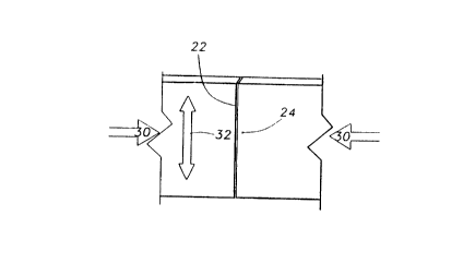
A method of forming vehicle wheel rims includes
utilizing linear friction welding. A generally planar
piece of metal material (20) is placed into a coil position
with two ends (22, 24) in abutment. The abutting ends
are oscillated or moved, in a generally linear pattern
(32), relative to each other to increase the temperature
of the metal at each end. After the temperature has
been increased sufficiently, without reaching the melting
temperature of the metal, the linear motion is stopped.
The ends are then aligned precisely and forced together
with an increased axial load (34). After cooling, the two
ends are permanently joined together with an essentially
defect-free welded joint.


French Abstract

Un procédé de formage de jantes de roues pour véhicules consiste à utiliser le soudage par friction linéaire. On donne à une pièce sensiblement plane en matériau métallique (20) une forme enroulée avec deux extrémités (22, 24) en aboutement. Les extrémités en aboutement sont oscillées ou déplacées l'une par rapport à l'autre, de manière sensiblement linéaire (32), afin d'augmenter la température du métal à chaque extrémité. Une fois que l'on a augmenté suffisamment la température, sans atteindre la température de fusion du métal, on stoppe le mouvement linéaire. On aligne les extrémités avec précision et on les force à s'unir sous l'effet d'une charge axiale accrue (34). Après refroidisssement, on unit les deux extrémités de façon permanente avec un joint soudé sensiblement sans défaut.

Claims

Note: Claims are shown in the official language in which they were submitted.


7

1. A method of making a vehicle wheel rim (S1), comprising the steps of:
(a) manipulating a generally planar piece of metal (20), having a first (22)
and second
(24) longitudinal end, into a generally cylindrical configuration with the
first end facing the
second end;
(b) forcing the first end against the second end using a first force (30)
having a first
magnitude and a direction that is generally tangential to said cylindrical
configuration where said
ends are forced against each other;
(c) moving the first end relative to the second end while maintaining the
first end
against the second end to thereby increase a temperature of each end; and
(d) forcing the first end against the second end using a second force (34)
having said
direction and a second magnitude that is greater than the first magnitude such
that the two ends
are fixedly joined together.

2. The method of Claim 1, wherein step (c) is performed by moving the first
end
(22) along a generally linear path.

3. The method of Claim 2, wherein step (c) is performed by repeatedly moving
the
first end (22) along a generally linear path in a first direction for a
preselected distance and in
an opposite direction for a preselected distance.

4. The method of Claim 3, wherein the generally linear path is generally
parallel to
an axis of the cylindrical configuration.

5. The method of Claim 1, wherein step (d) includes the substeps of stopping
the
movement of step (c); aligning the first and second ends in a preselected
alignment; forcing the
first end against the second end; and thereafter allowing the first and second
ends to cool.


CLAIMS

6. The method of claim 1, wherein the piece of metal comprises an aluminum
alloy.

7. The method of claim 1, wherein the piece of metal comprises a steel alloy.

8. The method of claim 1, further comprising the step of machining the rim
to form edges after performing step (D).

5


9

9. A method of making a vehicle wheel rim (51), comprising the steps of:
(a) manipulating a piece of metal (20), having a first (22) and second
longitudinal end
(24) with a length (27), into a generally cylindrical configuration with the
first end facing the
second end;
(b) forcing the first end against the second end using a first force (30)
having a first
magnitude and a direction that is generally tangential to said cylindrical
configuration where said
first end faces said second end;
(c) moving the first end relative to the second end while maintaining the
first end
against the second end to thereby increase a temperature of each end;
(d) stopping the movement of step (c);
(e) holding the first end against the second end such that the entire length
of the first
end is in contact and aligned with the entire length (27) of the second end;
(f) forcing the first end against the second end using a second force (34)
having said
direction and a second magnitude that is greater than the first magnitude; and
(g) allowing the temperature of the first and second ends to decrease such
that the two
ends are fixedly joined together.

10. The method of Claim 9, wherein step (d) is performed before the
temperature
from step (c) has reached a predetermined melting temperature of the metal.

11. The method of Claim 9, further comprising the step (h) roll forming the
rim after
performing step (g) to form edges on the rim.


Description

Note: Descriptions are shown in the official language in which they were submitted.


CA 02262784 1999-02-09
WO 98/06532 PCT/US97/13814
LINEAR FRICTION WELDING PROCESS
FOR MAKING WI~EL RIMS
BACKGROUND OF THE INVENTION
This invention generally relates to a process for making vehicle wheel rims
that
includes using linear friction welding.
Currently, vehicle wheel rims are assembled with a process including flash
butt
welding prior to flanging and roll forming operations. Conventional wheel rim
welding
methods have a number of associated drawbacks. For example, flash butt welding
causes
the need for rework and introduces a potential for flat spot defects. Flat
spot defects are
detrimental in forming wheel rims because they can create continuous leak
paths, which
would render the wheel rim ineffective. Accordingly, during or after an
assembly
process, wheel rims need to be immersion leak inspected. This procedure is
time
consuming and can be burdensomely expensive because of the labor involved.
Further, flash butt welding requires high energy usage. Another disadvantage
is
the measures that must be taken to minimize risks associated with introducing
pollutants
into the air. Flash butt welding can also produce excessive flash, which adds
to the initial
raw material cost. Additionally, modern wheel rims are made from differing
materials
and it can be difficult to accommodate such materials in a flash butt welding
process.
Moreover, different welding machines are required to weld different materials
such as
steel or aluminum. Further, conventional welding practices such as flash butt
welding
alter the final microstructure in undesirable ways resulting in reduced
formability.
Accordingly, it is desirable to provide a process for assembling wheel rims
that increases
the speed of production and overcomes the other drawbacks associated with
conventional
processes.
This invention provides an assembly process that overcomes the drawbacks and
shortcomings of conventional processes. Linear friction welding is utilized in
the
assembly process to provide more reliable welding joints and to eliminate the
drawbacks
associated with flash butt welding. Linear friction welding is a process that
has been used
and is known in the aerospace industry. Generally, it involves bringing two
metal objects
in direct contact under an axial load. The two objects are then moved relative
to each
1


CA 02262784 1999-02-09
WO 98/06532 PCT/US97/13814
other in a generally linear fashion to increase the temperature of the metal.
Before the
temperature reaches the melting point of the material, the relative linear
motion is stopped
and the axial load is increased forcing the two objects against each other.
The result is
a high strength bond having a uniform microcrystaliine structure that is
highly reliable.
SUMMARY OF THE INVENTION
In general terms, the method associated with this invention is for making a
vehicle
wheel rim out of a generally planar piece of metal. First, the piece of metal
is
manipulated into a generally cylindrical or coiled configuration. The piece of
metal has
two ends and the two ends are arranged to be directly facing each other when
the piece
of metal is in the cylindrical configuration. The first end is then forced
against the second
end. One end is then moved in a generally linear pattern relative to the other
end while
the two ends are maintained against each other. This relative linear movement
increases
the temperature of the metal in each end. After the temperature has been
increased to a
desirable point, hut without reaching the melting temperature of the material,
the relative
linear movement is then stopped. Then one end is precisely aligned with and
forced
against the other end using a force having a higher magnitude than the force
used to
maintain the two ends together in the earlier steps. Because of the raised
temperature of
the metal and the increased force, the two ends are fixedly joined together.
The various features and advantages of this invention will become apparent to
those
skilled in the art from the following detailed description of the preferred
embodiment.
The drawings that accompany the detailed description can be described as
follows.
BRIEF DESCRIPTION OF THE DRAWINGS
Figure 1 is a perspective view of a piece of material to be used to form a
wheel
rim according to this invention.
Figure 2 illustrates the material from Figure 1 in a coiled configuration.
Figure 3a illustrates a portion of the embodiment of Figure 2 and
schematically
shows an initial phase of the joining process according to this invention.
Figure 3b shows a later phase of the joining process according to this
invention.
Figure 3c schematically illustrates the completion of a joining process
according
to this invention.
Figure 4 shows the final wheel.
2


CA 02262784 1999-02-09
WO 98/06532 PCT/US97/13814
DETAILED DESCRIPTION OF THE PREFERRED EMBODIMENT
Figure 1 illustrates a generally planar piece of metal material 20. Suitable
metal
materials for use in a method according to this invention include aluminum
alloys and
steel alloys or other metal materials. The sheet of metal 20 has a thickness
26, a width
27 and a length 28. The thickness 26 and the width 27 define the size of a
face at each
end 22 and 24. In one example, the preferred thickness 26 is approximately 3
mm and
the preferred width 27 is approximately 170 mm. The material dimensions will
vary
depending on the requirements for the wheel rim.
Figure 2 illustrates the sheet of metal 20 placed in a generally cylindrical
or coiled
configuration. The faces of the first end 22 and the second end 24 are
directly opposing
each other. According to the method of this invention, the first face 22 is
brought in
direct contact with the second face 24. Designing the machinery for
manipulating the
piece of metal 20 from the generally flat configuration of Figure 1 into the
coiled
configuration of Figure 2 is within the ability of those skilled in the art
and, therefore,
need not be further described in this specification. Holding structure H is
shown
schematically, and can function to hold the ends together, and also to move
one end
relative to the other.
Figure 3a schematically illustrates the beginning phases of the joining
process
according to this invention. The first end 22 is placed in direct contact with
the second
end 24. Importantly, the entire face of the first end 22 is perfectly aligned
with the entire
face of the second end 24. The two ends are forced together using a force
schematically
illustrated by the arrows 30. While maintaining the two ends in contact, the
first end 22
is oscillated or moved in a generally linear path relative to the second end
24. The first
end 22 preferably is oscillated back and forth as schematically illustrated by
the arrows
32. The first end 22 preferably is moved a distance of approximately 3 mm in
each
direction at a frequency of approximately 70 to 100Hz. This process is
continued until
a temperature increase occurs in the first end 22 and the second end 24.
Figure 3b schematically illustrates a subsequent portion of the assembly
process.
After the temperature of the metal in the first and second ends has been
increased
appropriately, the relative linear or oscillating motion is stopped.
Importantly, the linear
motion is stopped before the temperature of the metal reaches its melting
point. After the
3


CA 02262784 1999-02-09
WO 98106532 PCT/US97I13814
relative linear movement is stopped, the first end 22 is moved to be perfectly
aligned with
the face of the second end 24. Then, an increased force, schematically
illustrated by the
arrows 34, forces the first end against the second end. Because of the
increased
temperature in the first and second end, a flash 36 of material is extruded
between the
first end 22 and the second end 24. Any undesirable flash can be removed
before or after
it cools. After cooling, the first end 22 is permanently bonded to the second
end 24.
Figure 3c schematically illustrates a completed joint 40 between the first end
22
and the second end 24. After the above procedures are completed, the wheel rim
can be
flared and roll formed according to conventional methodology in order to bring
the wheel
riminto the desired shape.
Assembling wheel rims according to this invention provides significant
advantages.
These advantages include a relatively large savings in raw material cost
because of
reduced flash, eliminating the need for later leak inspection because of the
accuracy and
reliability of the linear friction welding procedure described above, reduced
energy
consumption, and eliminating the introduction of pollutants into the air.
Moreover, the
assembly process, according to this invention, results in a fine grain, fully
recrystallized
microstructure that is free of defects. Further, the wheel rim cylinder has
excellent
formability during the flaring and roll forming processes. Additionally,
separate
machinery is not required for different materials. In other words, steel
alloys and
aluminum alloys can be utilized in the same machine when the wheel rim is
formed
according to the method of this invention.
Figure 4 shows the final wheel 50 having a rim S 1 with roll formed edges 52
and
a tire 54 mounted on the rim 51. As set forth above, the inventive method
improves the
quality of the wheel 50.
The above description is exemplary rather than limiting in nature. Variations
and
modifications to the disclosed embodiment will become apparent to those
skilled in the art
that do not necessarily depart from the spirit of this invention. Accordingly,
the legal
scope given to this invention can only be determined by studying the appended
claims.
4

Representative Drawing
A single figure which represents the drawing illustrating the invention.
Administrative Status

For a clearer understanding of the status of the application/patent presented on this page, the site Disclaimer , as well as the definitions for Patent , Administrative Status , Maintenance Fee  and Payment History  should be consulted.

Administrative Status

Title Date
Forecasted Issue Date 2004-12-21
(86) PCT Filing Date 1997-08-07
(87) PCT Publication Date 1998-02-19
(85) National Entry 1999-02-09
Examination Requested 2002-02-07
(45) Issued 2004-12-21
Deemed Expired 2008-08-07

Abandonment History

There is no abandonment history.

Payment History

Fee Type Anniversary Year Due Date Amount Paid Paid Date
Registration of a document - section 124 $100.00 1999-02-09
Application Fee $300.00 1999-02-09
Maintenance Fee - Application - New Act 2 1999-08-09 $100.00 1999-07-21
Maintenance Fee - Application - New Act 3 2000-08-07 $100.00 2000-08-03
Maintenance Fee - Application - New Act 4 2001-08-07 $100.00 2001-07-26
Request for Examination $400.00 2002-02-07
Maintenance Fee - Application - New Act 5 2002-08-07 $150.00 2002-07-18
Maintenance Fee - Application - New Act 6 2003-08-07 $150.00 2003-07-29
Maintenance Fee - Application - New Act 7 2004-08-09 $200.00 2004-08-06
Final Fee $300.00 2004-10-04
Maintenance Fee - Patent - New Act 8 2005-08-08 $200.00 2005-07-20
Maintenance Fee - Patent - New Act 9 2006-08-07 $400.00 2006-09-14
Owners on Record

Note: Records showing the ownership history in alphabetical order.

Current Owners on Record
MERITOR LIGHT VEHICLE SYSTEMS, INC.
Past Owners on Record
MAHONEY, MURRAY
ROCKWELL INTERNATIONAL CORPORATION
ROCKWELL LIGHT VEHICLE SYSTEMS, INC.
Past Owners that do not appear in the "Owners on Record" listing will appear in other documentation within the application.
Documents

To view selected files, please enter reCAPTCHA code :


To view images, click a link in the Document Description column. To download the documents, select one or more checkboxes in the first column and then click the "Download Selected in PDF format (Zip Archive)" or the "Download Selected as Single PDF" button.

List of published and non-published patent-specific documents on the CPD .

If you have any difficulty accessing content, you can call the Client Service Centre at 1-866-997-1936 or send them an e-mail at CIPO Client Service Centre.


Document
Description 
Date
(yyyy-mm-dd) 
Number of pages   Size of Image (KB) 
Drawings 1999-02-09 1 24
Representative Drawing 1999-05-06 1 3
Abstract 1999-02-09 1 54
Description 1999-02-09 4 229
Claims 1999-02-09 3 122
Cover Page 1999-05-06 1 45
Cover Page 2004-11-18 1 37
Correspondence 2005-06-22 1 16
PCT 1999-02-09 16 596
Assignment 1999-02-09 15 563
Prosecution-Amendment 2002-02-07 1 30
Correspondence 2004-10-04 1 34
Fees 2002-07-18 1 33
Fees 1999-07-21 1 28
Fees 2004-08-06 1 31
Correspondence 2005-07-20 1 46