Note: Descriptions are shown in the official language in which they were submitted.
CA 02266044 2003-02-07
METHOD FOR GORNEAL LASER SURGERY
FIEbD OF THE INVENTION
The present invention pertains generally to ophthalmic surgery which is
useful for correcting vision deficiencies. More particularly, the present
invention pertains to methods which surgically correct the vision of a patient
by removing portions of the stroma to reshape the cornea. The present
invention is particularly, but not exclusively useful as a method for using a
laser beam to photodisrupt corneal tissue to achieve access to a
predetermined volume of strornal tissue which needs to be removed to correct
the vision of the patient.
BACKGROUND OF THE INVENTION
Vision impairment can occur for many reasons, and be the result of
many causes. One, all too common, cause for vision impairment results from
a defective condition of the eye which occurs when the refractive
characteristics of the cornea do not cause parallel rays of light to focus on
the
retina. When the eye is at rest, and the rays of light focus in front of the
retina, the condition is known as myopia (i.e. near-sightedness). On the other
hand, when the rays of light focus behind the retina, the condition is known
as
hypermetropia or hyperopia (i.e. far-sightedness). Botlo myopic and hyperopic
conditions result in varying degrees of vision impairment and, as is well
known, in most cases the conditions are correctable.
1
CA 02266044 1999-04-O1
Spectacles or eyeglasses are commonly used to correct myopic or
hyperopic conditions. For various reasons, however, many persons who
suffer with these conditions prefer not to wear eyeglasses. Fortunately for
these individuals, it is known that surgical procedures can be employed which
will reshape the cornea in ways that are effective in changing its refractive
characteristics. For example, U.S. Patent NO. 4,665,913 which issued to
L'Esperance for an invention entitled "Method for Ophthalmological Surgery",
and U.S. Patent No. 4,669,466 which issued to L'Esperance for an invention
entitled "Method and Apparatus for Analysis and correction of Abnormal
Refractive Errors of the Eye" both disclose a laser system which photoablates
corneal tissue from the anterior surface of the eye. In a different manner,
U.S. Patent No. 4,988,348 which issued to BiUe for an invention entitled
"Method for Reshaping the Cornea", and which is assigned to the same
assignee as the present invention, discloses a procedure whereby corneal
tissue is first removed to correct vision, and then the newly created surface
is
smoothed.
Rather than remove and reshape portions of the anterior portion of the
eye to correct refractive detects, some procedures for reshaping the cornea
have suggested intrastromal photoablation for removal of only stromal tissue.
As an example of such a procedure, U.S. Patent No. 4,907,586, which issued
to Bille et al. for an invention entitled "Method for Reshaping the Eye"
discloses an intrastromal photodisruption technique for reshaping the cornea.
Another eXample of a procedure which is intended to essentially remove only
stromal tissue is the so-ca8ed "flap and zap" procedure. For this procedure,
an anterior portion of the cornea is removed and a portion of the exposed
stroma is then photoablated. The previously removed anterior portion of the
cornea is then repositioned on the cornea to cover the photodisruption. This
2
CA 02266044 1999-04-O1
procedure, like the procedure disclosed in Bille et al. '586, has as its
objective
the removal of only stromal tissue with the consequent preservation of
anterior corneal tissue. A significant downside for the "flap and zap"
procedure, however, is the possibility that the previously removed anterior
portion of the cornea may again become detached. While the intrastromal
procedure disclosed by Bille et al. does not lead to this detachment problem
it
can, in some cases, require extensive laser photodisruption and be time
consuming.
In one aspect, it is appreciated by the present invention that the "flap
and zap" procedure can be made more effective and efficient if the "flap" that
is created can somehow be repositioned in an interiodcing relationship with
the undisturbed corneal tissue. To accomplish this, the present invention
recognizes that it would be desirable if, first, a "flap" with an
interiockable
configuration is created. The flap could then be lifted to expose the corneal
tissue that is to be removed and, next, after the desired amount of corneal
tissue is removed, the flap could be repositioned and interlocked with
undisturbed corneal tissue to hold the "flap" in place during the healing
process.
The use of laser systems for ophthalmic surgical procedures, such as
for other procedures contemplated for the present invention, is particularly
appropriate due to the extreme precision required when corneal tissue is to
be removed. Specifically, depending on the diameter and the general shape
of the tissue volume to be removed, it is known that the removal of a layer of
stromal tissue which is only approximately ten microns thick will result in a
one diopter change. More practically, by way of example, the removal of a
lens shaped volume of tissue which is four millimeters in diameter and
approximately fifty microns thick at its center will result in a refractive
3
CA 02266044 1999-04-O1
correction of approximately four diopters. In almost all cases, for precise
vision corrections which can stay within a one diopter accuracy, the surgical
procedure employed must be capable of removing corneal tissue having a
thickness which is accurate to within less than ten microns. Furthermore, this
degree of accuracy applies for any refractive correction regardless of the
total
amount of correction required.
It happens that the correction of myopia requires removal of a
differently shaped volume of corneal tissue than does the correction of
hyperopia. Also, the limits of potential correction are different.
Specifically,
for a myopic correction it is known that a lentoid or lens shaped volume of
stromal tissue needs to be removed. At the present time, myopic corrections
of up to approximately thirty diopters can be reasonably expected. On the
other hand, corrections of hyperopic conditions can be made up to only about
fifteen diopters. Furthermore, for a hyperopic correction a generally doughnut
shaped volume of stromal tissue, rather than a lens or lentoid shaped volume,
needs to be removed.
In light of the above, it is an object of the present invention, to provide
a method for corneal laser surgery which corrects the refractive
characteristics of the cornea by removing only stromal tissue with minimal
photodisruption of the tissue. Another object of the present invention is to
provide a method for corneal laser surgery which essentially maintains the
structural integrity of corneal tissue. Still another object of the present
invention is to provide a method for corneal laser surgery which can be
accomplished with a high level of precision when cutting corneal tissue by
photodisruption. Another object of the present invention is to provide a
method for corneal laser surgery which creates an interlodcing~ flap that can
be lifted to remove a predetermined volume of tissue from the stroma and
4
CA 02266044 1999-04-O1
then repositioned in an interlocking relationship with undisturbed corneal
tissue to hold the flap in place during subsequent healing. Yet another object
of the present invention is to provide a method for corneal laser surgery
which
is relatively easy to practice and comparatively cost effective.
SUMMARY OF THE PREFERRED EMBODIMENTS
In accordance with the present invention, a method for corneal laser
surgery includes the step of first determining a volume of stromal tissue
which
needs to be removed in order to correct the vision of the patient. This volume
of stromal tissue which is to be removed is formed as a lentoid that is
defined
by an anterior surface and a posterior surface. Accordingly, these surfaces
are situated relative to each other so that the lentoid shaped volume of
tissue
to be removed is positioned therebetween.
A pulsed laser beam is focused to position its focal point at a
preselected start point on the posterior surface of the lentoid. The focal
point
is then moved over the posterior surface to photodisrupt tissue on this
surface
and separate the lentoid from surrounding tissue. The same process is
repeated for the anterior surface and the result is that the lentoid of
stromal
tissue to be removed is completely surrounded by photodisrupted tissue and
thereby free of attachments to surrounding tissue.
In one embodiment of the present invention, looking at the eye in the
direction from anterior to posterior, the posterior surface is shaped as a
concave plate and the anterior surface is shaped as a convex plate. The
removal of the resultant lens shaped tissue lentoid or disc is specifically
intended to correct myopia. For the particular embodiment of the present
invention wherein the correction of myopia is the desired result, it will be
5
CA 02266044 1999-04-O1
appreciated that the anterior surface or the posterior surface, or both, can
be
substantially flat. Also, the concave posterior surface could be modified to
be
a convex surface and thus have a curved surface which is similar to the
anterior surface. On the other hand, in another embodiment of the present
invention, the posterior surface is shaped as a concave annular surface and
the anterior surface is shaped as a convex annular surface. In this instance
the stroma! tissue to be removed is a ring shaped or doughnut shaped
volume which is specifically intended to correct hyperopia.
Regardless whether the volume is lens shaped or ring shaped, the
method of the present invention also contemplates the creation of a channel
through the stroma which provides for extracorporeal access to the
encapsulated portion of the stroma. The encapsulated portion of the stroma
can then be accessed, gripped, and removed or retrieved from the stroma
through the channel. As intended for the present invention, with the removal
of the lentoid volume of strornal tissue, the cornea is appropriately reshaped
to correct the particular vision detect of the patient.
As intended for the present invention, the laser system to be used for
accomplishing the methods will incorporate a beam of sequential laser
pulses. Further, it is contemplated that the duration of laser pulses in the
beam will be in the nanosecond, picosecond or femtosecond ranges.
For an alternative method of the present invention, the volume of
tissue to be removed is as determined above. For this case, however, a flap
is created which can be lifted from the cornea to provide for access to the
tissue volume that is to be removed. Specifically, the flap is created as a
layer of tissue having one surface which is a portion of the anterior surface
of
the cornea, and having an opposite surface therefrom which can either be a
portion of the posterior surface of the cornea or a surface that is fashioned
6
CA 02266044 1999-04-O1
and cut from the stroma of the cornea. Further, this layer of tissue can be
hinged to thereby allow rotation of the flap about the hinge, or it can be
formed as an unhinged plug which can be entirely removed from the cornea
and subsequently replaced. In either case the layer (regardless whether it be
a flap or a plug), is created and formed with an undercut region which
restrains its movement in an anterior direction.
BRIEF DESCRIPTION OF THE DRAWINGS
The novel features of this invention, as well as the invention itself, both
as to its structure and its operation will be best understood from the
accompanying drawings, taken in conjunction with the accompanying
description, in which similar reference characters refer to similar parts, and
in
which:
Figure 1 is a perspective view of a patient being treated with the
method of the present invention;
Figure 2 is a perspective view of an eye;
Figure 3 is a cross sectional view of the cornea of the eye as seen
along the line 3-3 in Figure 2 showing a representative portion of stromal
tissue to be removed for the correction of myopia;
Figure 3A is a cross-sectional view of a lentoid having a convex
anterior surface and a concave posterior surface;
Figure 36 is a cross-sectional view of a lentoid having a convex
anterior surface and a concave posterior surface which are separated by a
contiguous flat annular surface therebetween;
7
CA 02266044 1999-04-O1
Figure 3C is a cross-sectional view of a lentoid having a flat anterior
surface and a flat posterior surface which are separated by a contiguous flat
annular surface therebetween;
Figure 4 is a plan view of the cornea of the eye as seen in the direction
of the line 4-4 in Figure 2 showing a representative path for movement of the
laser beam focal point to prepare the portion of stromal tissue shown in
Figure 3 for removal from the cornea:
Figure 5 is a cross sectional view of the cornea of the eye as seen
along the line 3-3 in Figure 2 showing a representative portion of stromal
tissue to be removed for the correction of hyperopia;
Figure 6 is a plan view of the cornea of the eye as seen in the direction
of the tine 4-4 in Figure 2 showing a representative path for movement of the
laser beam focal point to prepare the portion of stromal tissue shown in
Figure 5 for removal from the cornea;
Figure 7 is a cross sectional view of the cornea of the eye as seen
along the line 3-3 in Figure 2 showing the gripping of the portion of stromal
tissue to be removed;
Figure 8 is a cross sectional view of the cornea of the eye as seen
along the line 3-3 in Figure 2 showing the retrieval of the portion of stromal
tissue to be removed.
Figure 9 is a cross sectional view of the cornea of an eye; and
Figure 10 is a plan view of the portion of the cornea shown in Figure 9
looking at the anterior surface thereof in a posterior direction.
8
CA 02266044 1999-04-O1
DESCRIPTION OF THE PREFERRED EMBODIMENT
Referring initially to Figure 1, an apparatus 10 for generating a laser
beam 12 is shown. Specifically, the laser beam 12 is shown being directed
onto an eye 14 of a patient 16. For purposes of the present invention, the
apparatus 10 is capable of generating a pulsed laser beam 12 having
physical characteristics similar to those of the laser beams generated by a
laser system as disclosed and claimed in U.S. Patent No.4,764,930, which is
also assigned to the assignee of the present invention. Furthermore, the
present invention contemplates the use of a pulsed laser beam 12 which has
pulses with durations as long as a few nanoseconds or as short as only a few
femtoseconds.
Figure 2 shows the anatomical structure of eye 14 and, specifically,
that the cornea 18 is anterior to the pupil 20, the iris 22, and the sclera
24.
Additionally, Figure 2. indicates that the optical axis 26 of eye 14 passes
through the cornea 18. Consequently, the tissue of comes 18 is transparent
to visible light.
In Figure 3 it can be seen that the cornea 18 includes five anatomically
definable layers of tissue. Going in a direction from anterior to posterior in
Figure 3, the tissue layers of the cornea are: epithelium 26, Bowman's
membrane 28, stroma 30, Decemet's membrane 32 and endothelium 34. Of
these, the stroma 30 is of most importance for the present invention as it
contains the only tissue which is to be removed for correction of the
patient's
vision.
As indicated above, the correction of a myopic condition can be
accomplished by the removal of a predetermined volume of stromal tissue.
9
CA 02266044 1999-04-O1
As also indicated above, the particular volume of stromal tissue to be
removed for the correction of myopia will depend on the amount of correction
required and will be a lens or lentoid shaped volume. Such a lentoid volume
36 is shown in cross section in Figures 3 and 3A. As shown, it is to also be
appreciated that the lentoid volume 36 will be defined by an anterior surface
38 and a posterior surface 40. Together, the anterior surface 38 and the
posterior surface 40 will completely enclose or encapsulate the lentoid
volume 36 of stromal tissue 30 which is to be removed. To obtain the lens
shape of the lentoid volume 36 it will be understood and further appreciated
that, when considering lentoid volume 36 in a direction from anterior to
posterior, the anterior surface 38 may be convex in shape and the posterior
surface 40 may be concave in its shape.
It is to be appreciated that the actual shape for lentoid 36 may vary
according to the needs and desires of the physician. For example, several
possible shapes for ientoid 36 are shown in Figures 3A, 3B and 3C.
Specifically, the lentoid 36 shown in Figure 3A is as suggested above where
the anterior surface 38 is convex and the posterior surface 40 is concave.
Figure 3B shows a variation from this shape wherein the anterior concave
surface 38' is separated from the posterior concave surface 40' by a
substantially flat annular surface 41. As shown, the flat annular surface 41
is
contiguous with both the anterior surface 38' and the posterior surface 40'.
Figure 3C shows yet another variation for lentoid 36 wherein both the anterior
surface 38" and the posterior surface 40" are flat. Again, the anterior
surface
38" and the posterior surface 40" are separated by the contiguous flat annular
surface 41.
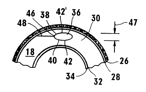
The creation of the anterior surface 38 and posterior surface 40 of
lentoid volume 36 will, perhaps, be best appreciated with cross reference
CA 02266044 1999-04-O1
between Figure 3 and figure 4. In Figure 4, a predetermined start point 42 is
shown, which is preferably on the posterior surface 40. The laser beam 12 is
then focused initially on the predetermined start point 42 and, subsequently,
the focal point of the laser beam 12 is moved according to computer
programmed instructions along the spiral path 44. The spiral projection of the
laser beam's focal point continues along spiral path 44 to create the concave
posterior surface 40 until it reaches a point 46. Upon reaching the point 46
for the first time, the laser beam 12 is focused at a start point 42' on the
anterior surface 38 of lentoid volume 36. The focal point of the laser beam 12
is then moved, again according to computer programmed instructions along a
spiral path 42' to create the convex anterior surface 38 until the focal point
again arrives at the point 46. With these actions the lentoid volume 36 is
encapsulated and surrounded by photodisrupted tissue in the surfaces 38
and 40. For most applications the maximum distance 47 between the
surfaces 38 and 40 will not exceed two hundred and fifty microns.
A channel 48 is next formed into the cornea 18 to provide for
extracorporeal access to the lentoid volume 36. Specifically, the channel 48
will be created by the photodisruption of stromal tissue 30 in a manner
similar
to that used for the creation of anterior surface 38 and posterior surface 40.
To accomplish this, a complete or a partial, or interrupted, spiral path 50 is
followed by the focal point of laser beam 12. As can be appreciated by
reference to Figure 4, for a partial spiral path 50 the activation of laser
beam
12 can be interrupted and turned off during the excursion of its focal point
through an arc of predetermined magnitude. In Figure 4 the arc in which the
laser beam i 2 is inactivated is shown as the space 52 and is estimated to be
approximated two hundred and seventy degrees. On the other hand, the
11
CA 02266044 1999-04-O1
laser beam 12 is activated and the channel 48 is created over the remaining
approximately ninety degrees of travel for the laser beam 12 focal point.
As implied above, it may be preferable to generate a complete spiral
path 50, rather than the partial spiral path 50 shown in Figure 4. To do this,
laser beam 12 remains activated during photodisruption of stromal tissue
during each complete 360° sweep of laser beam 12 along path 50. Thus,
no
space 52 is created and, instead, the spiral path 50 creates a layer of
photodisrupted tissue. With this complete spiral path 50 pattern, it is
subsequently possible to create an access channel 48 to the lentoid volume
36 from any direction. Additionally, the tissue of stroma 30 which is
photodisrupted by each complete 360° sweep of laser beam 12 is
symmetrically disposed around the lentoid volume 36. In some cases, this
symmetrical disposition of photodisrupted tissue may be necessary in order to
prevent a later development of irregular astigmatism.
Turning now to Figure 5, a procedure for the treatment of hyperopia is
indicated. As shown, the annular tissue volume 54 to be removed from
stroma 30 in this procedure has a slightly different shape than is required
for
the treatment of myopia. Specifically, the annular tissue volume 54 is annular
shaped. One way to create this annular tissue volume 54 is to initially focus
the laser beam 12 to a predetermined start point 56 on annular tissue volume
54. The posterior surface 58 of annular tissue volume 54 is then created by
moving the focal point of laser beam 12 along a depth variable spiral path 60
until it reaches a point 62 to create a concave posterior surface 58. The
focal
point is then returned to the start point 56 and again moved along a spiral
path 60' of variable depth to create the convex anterior surface 64 for
annular
tissue volume 54. Upon reaching the point 62 for the second time, a channel
12
CA 02266044 1999-04-O1
48 can be created in substantially the same manner as disclosed above for
the procedure to create a myopic condition.
In addition to the creation of the annular tissue volume 54, the
procedure for creating the annular tissue volume 54 of stromal tissue 30 also
requires that the annular tissue volume 54 be severed on a plane 66 which is
between and generally perpendicular to the anterior surface 64 and the
posterior surface 58. As will be appredated by the skilled artisan, this
severance of annular tissue volume 54 along plane 66 allows for removal of
the annular tissue volume 54 through the channel 48. Additionally, if desired
to further facilitate removal of the annular tissue volume 54 from cornea 18,
the annular tissue volume 54 can also be severed along a plane 68 which is
generally diametrically opposite from the plane 66 and which, like plane 66,
is
between and generally perpendicular to the surfaces 58 and 64.
Once the lentoid volume 36 or the annular tissue volume 54 of stromal
tissue 30 has been created, as disclosed above, a device 70 can be inserted
through channel 48, as shown in Figure 7, to grip and then remove the
particular volume from stroma 30, as shown in Figure 8. For purposes of the
present invention, the device 70 can be any instrument known in the pertinent
art, such as a tweezers or a suction probe.
In another aspect of the present invention, the apparatus 10 can be
used to create a section of corneal tissue which can be moved to expose, and
thereby establish access to, the capsule volume 36 that is to be removed.
For this particular procedure a layer 72 of corneal tissue is created which
has
an undercut region 74 that structurally interacts, or interlocks, with an
intact
overlap region 76 of the cornea. The idea here is to have the undercut region
74 interlock with the overlap region 76 so that the layer 72 does not
unintentionally move in an anterior direction. For purposes of this
disclosure,
13
CA 02266044 1999-04-O1
the anterior direction is to be considered as the general direction taken from
the posterior surface 78 of cornea 18 (i.e. endothelium 34j toward the
anterior
surface 80 of cornea 18 (i.e. epithelium 26). Contrarily, the posterior
direction
is taken to be from the anterior surface 80 back toward the posterior surface
78.
For a description of how to create the layer 72, it is best to first identify
a reference axis 82 from which distances and directions can be taken. For
this purpose, consider the reference axis 82 to be oriented generally
perpendicular to the anterior surface 80 of cornea 18, and to intersect the
anterior surface 80 at a start point 84. The actual cutting the cornea 18 can
be accomplished using any device well known in the art. For purposes of the
present invention, however, it is prefer-ed that corneal incisions be made
using a laser light beam.
The creation of layer 72 begins by cutting the corneal tissue along a
path 86 which is oriented at an angle 88 from the reference axis 82, and
which extends from the start point 84 to a turn point 90. In practice,
depending upon the particular desires of the operator, the path 86 can result
in several different configurations for layer 72. One configuration, of
course,
is as shown in Figure 9. For this particular configuration, the path 86 is
essentially a straight line. In this case, the straight line is set at an
acute
angle 88 relative to the reference axis 82, and it extends from the start
point
84 to the turn point 90. The undercut region 74 is then formed by cutting back
toward the reference axis 82 along a path 92 which generally parallels the
posterior surface 78. Again, depending on the desires of the operation, the
path 86 can be something other than a straight line, so long as the start
point
88 is generally located on the reference axis 82 and the turn point 90 is
distanced from the axis 82 to create the undercut region 74.
14
CA 02266044 1999-04-O1
The implication from the above disclosure is that a plurality of different
cuts, each along the different paths 86 and 92, need to be made in order to
create the layer 72. Reference to Figure 10, shows what the result of these
several cuts might be. In Figure 10 it will be seen that a plurality of start
points 84 can be selected to establish a periphery 94. -As shown, the
periphery 94 is curvilinear and can be generally defined by a radius of
curvature 96. Further, it can be appreciated by reference to Figure 10 that a
plurality of turn points 90 can be selected to establish a periphery 98. As
shown, the periphery 98 is also curvilinear and can be generally defined by a
radius of curvature 100. In order for the undercut region 74 to be
established,
it will be understood that the radius of curvature 100 must be greater than
the
radius of curvature 96. Additionally, as shown in Figure 10, the peripheries
94 and 98 do not close. Thus, the a hinge area 102 is created and the layer
72 can be lifted as a flap in rotation about the hinge 102.
As an alternate configuration for the layer 72, it is to be appreciated
that the layer 72 can be configured as a plug, rather than a flap. fn this
case,
the peripheries 94 and 98 are closed paths, such as a circle. For this
configuration there is no hinge 102. Referring back to Figure 9, it will be
seen
that the plug configuration for layer 72 can be established by additional
cutting. Specfically, this requires additional cutting on path 92 along the
path
continuation 92' and along a path 106 from the anterior surface 80 to the path
i
92' (both path continuation 92' and path 106 are shown by dashed tine in
Figure 9).
Once the layer 72 has been created, either as a flap or a plug, the
layer 72 can be mechanically lifted to expose an underlying capsule volume
36. As indicated above, the volume 36 can have many different sizes and
shapes depending on the particular optical problem being confronted. In any
CA 02266044 1999-04-O1
case, once exposed, the volume 36 can be removed by procedures well
known in the pertinent art. Importantly, after the volume 36 is removed, the
layer 72 can be repositioned. When so repositioned, it is intended that the
undercut region 74 will interact with overlap region 76 to restrain any
further
movement of the layer 72 in an anterior direction.
For some procedures it may be preferable to establish access all the
way into eye. If so, the turn point 90 can be ignored and the path 86 be
extended from the anterior surface 80 all the way to the posterior surface 78.
Again, depending upon the extent of the cuts, and the respective resultant
peripheries 94 and 98, the layer 72 can be created as either a flap or a plug.
While the particular Method for Corneal Laser Surgery as herein
shown and disclosed in detail is fully capable of obtaining the objects and
providing the advantages herein before stated, it is to be understood that it
is
merely illustrative of the presently preferred embodiments of the invention
and
that no limitations are intended to the details of the construction or design
herein shown other than as defined in the appended claims.
16