Note: Descriptions are shown in the official language in which they were submitted.
CA 02266118 2003-04-29
VALVED BOTTLE CAP
BACKGROUND OF THE INVENTION
Field of Invention
The present invention relates generally to bottle caps which form closures on
containers
from which liquid and dry materials are dispensed.
Description of the Related Prior Art ' w
Dispensing systems such as those used on water coolers which use bottled
water, like the
one shown in U.S. Patent No. 5,121,778 (the " '778 patent"), are generally
equipped with
reservoirs. The reservoirs are kept filled with water supplied by an inverted
large capacity water
bottle. The capacity of such water bottles is typically five or six gallons,
although containers
of other capacities are also used.
In recent years, water cooler manufacturers have addressed problems with
traditional
water cooler systems. Those problems include the difficulty of inverting an
open water bottle,
and concerns relating to the growth of bacteria in the reservoirs resulting
from exposure of the
reservoir to the atmosphere. Examples of attempts to solve these problems are
shown in the
'778 patent, as well as in U.S. Patent No. 4,699,188 (the " ' 188 patent"). In
the ' 188 patent,
CA 02266118 1999-03-18
a probe capable of piercing a cap on the water bottle is rigidly connected to
the base of the
support for the water bottle. The bottle cap includes. a central tube with a
pierceable membrane
at one end of the tube. The tube is integrally formed with the bottle cap.
Earlier attempts to
solve problems associated with inverting a filled water bottle are shown in
U.S. Patent Nos.
4,846,236 and 4,597,423.
The system shown in the '778 patent includes a blunt probe which displaces a
frangible
plug integrally formed at one end of a central tube in the water bottle cap.
The blunt probe of
the '778 patent is equipped with means for pulling the frangible plug back
into engagement with
the central tube in the event that the bottle is lifted from the probe. This
provides clear
advantages as compared to systems in which a water bottle cap is completely
removed prior to
being inverted and placed on a water cooler. First, the problem of spilling
water, when the
bottle is initially installed, is solved, since the frangible connection
remains intact and the cap
remains sealed until a seal between the probe and tree central tube has been
achieved. Second,
the plug seals the central tube automatically upon removal of the bottle from
the cooler, even
if the bottle is not empty. This eliminates spillage if it becomes necessary
to remove the bottle
from the cooler before the bottle is empty. Such removal may be necessary, for
example, if
repair or relocation of the cooler is required.
Finally, the resealing of the cap by the plug upon removal of an empty bottle
provides
protection against contamination of the empty bottle on its return trip to a
water bottling facility.
The inability to remove and replace the plug without the use of a probe
provides the cap with
a form of tamper evidency upon which bottlers carp rely when deciding what
kind of cleaning
process to use in preparing a bottle for refilling.
2
CA 02266118 1999-03-18
However, the cap shown in the '778 patent has at least two inherent problems.
First,
there is a tendency for the edges of the central tube of the '778 cap to pry
the plug away from
its engagement with the blunt probe. When this happens, the plug does not
engage the central
tube and the water bottle is not sealed. This absence of a seal will result in
spillage if the bottle
is removed before it is empty, and in the loss of contamination protection for
its return trip to
the water bottling facility.
Another problem associated with the cap shown in the '778 patent is the
difficulty of
molding or constructing the cap as it is shown in th.e '778 patent. The cap
has a combination
of undercuts which make it impossible to mold the cap in one entire piece.
Unless the cap is
assembled from two pieces, such as those shown in Figure 8 of the '778 patent,
a situation
known as "trapped steel" will occur, which prevent: the cap from being removed
from a mold
without destroying the cap. The presence of the multiple undercuts and the
criticality of molding
the frangible connection between the plug and the central tube in the cap
requires that the cap
of the '778 patent be initially formed of two components. Those components
must subsequently
be welded or otherwise bonded together to form a single unitary cap. The
welding or bonding
operation is somewhat problematic in that the connection between the two
components must not
only be structurally sound, but must form a seal. In addition, the heat
generated by a sonic-
welding operation may detrimentally affect the frangible connection by
lowering the breaking
point of that connection. Maintaining a predictable and consistent breaking
point for the
frangible connection is required to ensure that the 'blunt probe fully engages
the plug prior to
breaking of the frangible connection.
3
CA 02266118 2003-04-29
A further problem associated with manufacture of the cap shown in the '778
patent
relates to the handling of the component which contains the frangible
connection. In order to
weld the two components which comprise the cap, the portion containing the
central tube and
the plug frangibly connected thereto must be fed or otherwise conveyed to a
position in which
it can be welded to the remaining part of the cap. Handling operations must be
done carefully
so as not to prematurely break or.weaken the frangible connection. If the
frangible connection
is weakened or otherwise improperly formed, the plug may have a tendency to
leak or
prematurely break free from the central tube of the cap before a secure
connection between the
plug and the probe has been achieved. When this occurs, the plug will come
floating to the
surface of the water in the bottle. This is a highly undesirable condition
referred to as creating
a "floater". The surface of the water is a highly visible location in most
cooler/bottle
arrangements, and users of the system do not like to see pieces of plastic
floating in the water
they are about to drink. Creating a "floater" also has the earlier discussed
disadvantages of
spillage upon early removal of the bottle, and the lack of a seal for the
bottle's return trip to the
bottling facility.
SUMMARY OF THE INVENTION
The above described problems and disadvantages are overcome by a cap for
bottles used
in water cooler systems which includes a main outer cap and an inner cap. The
inner cap forms
a seal on the outside surface of a central tube carried by the outer cap.
Further, by causing the
inner cap to seal against the outside surface of the central tube, the
tendency for the inner cap
to prematurely disengage from the probe is greatly reduced.
4
_. , ...__~,.~ __ T, w..-~....".."......~.~.~._-----.._-...,.._.
CA 02266118 2003-04-29
In one aspect of the present invention there is provided a
cap for sealing a container, said cap comprising an outer cap and an inner
cap, said
outer cap comprising a cylindrical skirt with at least one container gripping
formation on an
inside surface of said skirt for engaging a corresponding formation on a neck
of said container,
a tube generally cylindrical in shape and general 1y parallel to and
concentric with said skirt, said
tube and said skirt being joined by an annular base, said annular base
surrounding an axial
passageway extending through said base and through said tube, said inner cap
comprising a
sealing sleeve, said sealing sleeve fitting over and sealing against an
outside surface of said
tube, and a second sleeve adapted to engage a probe and hold said inner cap in
a position
adjacent to said probe.
In another aspect of the present invention there is provided a
closure and probe combination for dispensing flowable substances from a
container, said combination including a probe used to remove contents of said
container and
a closure comprising an outer cap and an inner cap, said outer cap comprising
a cylindrical skirt
with a container gripping formation on an inside surface of said skirt for
engaging a
corresponding formation on an outside surface of a neck of said container, a
tube generally
cylindrical in shape and generally parallel to and concentric with said skirt,
said tube and said
skirt being joined by an annular base, said annular base surrounding an axial
passageway
extending through said base and through said tube, said inner cap comprising a
sealing sleeve,
said sealing sleeve fitting over and sealing against an outside surface of
said tube, and a second
sleeve in said inner cap which engages and retains said inner cap in a
position adjacent to said
probe.
CA 02266118 2003-04-29
In yet another aspect of the present invention there is provided a
cap for sealing a container, said cap comprising an outer cap and an inner
cap,
said outer cap comprising a cylindrical skirt with at least one gripping
formation on an inside
surface of said skirt for engaging a corresponding formation on a neck of the
container, a tube
generally parallel to and concentric with said skirt, said tube and said skirt
being joined by an
annular base, said annular base surrounding an axial passageway extending
through said base
and through said tube, said inner cap comprising two generally concentric
sleeves, a firsf sealing
sleeve and a second probe-engaging sleeve, said first sealing sleeve fitting
over sealing against
an outside surface of said tube, and said second sleeve having at least one
probe engaging
formation useable to hold said inner cap in a position adjacent to a free end
of said probe, said
first sealing sleeve and said second probe-engaging sleeve having differing
transverse
dimensions, one end of said second sleeve having a closed end and defining a
recess for
receiving a tip of a probe, and said sealing sleeve defining a second recess
axially offset with
respect to said first recess and shaped to receive a free end of said tube.
These and other features and advantages of the invention will be better
understood upon
a reading of the following detailed description of the invention read in
conjunction with the
accompanying drawings, wherein:
6
CA 02266118 1999-03-18
BRIEF DESCRIPTION OF 'THE DRAWINGS
Figure 1 is a sectional view showing a cap of the present invention installed
on a
container neck;
Figure 2 is a bottom plan view of the cap shown in Figure 1;
Figure 3 is an enlarged sectional view showing a portion of the inner cap of
the present
invention just prior to its engagement with the central tube.
Figure 4 is a sectional view of the inner cap .component of the present
invention;
Figure S is a bottom plan view of the inner cap shown in Figure 4;
Figure 6 is an enlarged sectional view showing the cap of the present
invention, together
with a probe, just prior to or after the cap's engagennent with a probe;
Figure 7 is a bottom plan view of an alternative embodiment of the cap of the
present
invention; and
Figure 8 is a sectional view of the cap shown in Figure 7, together with a
sectional view
of the probe.
Figure 9 is an exploded sectional view of another alternative embodiment of
the cap of
the present invention, together with a probe and an adapter.
Figure 10 is an exploded sectional view of a further alternative embodiment of
the cap
of the present invention, together with a probe and an adapter.
7
CA 02266118 1999-03-18
DETAILED DESCRIPTION OF THE INVENTION
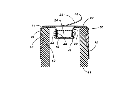
Figure 1 shows a container 11 with a bottle neck 10 onto which has been placed
a cap
12 of the present invention. The cap 12 is comprised of two components, an
outer cap 14 and
an inner cap 16. The outer cap 14 has a skirt 18, and a central tube 20 joined
to the skirt 18
by an annular base 22. The annular base 22 and the: central tube 20 define a
main passageway
24 through which fluid is intended to flow after the inner cap 16 is lifted
from the central tube
20 by a probe 30 (See Figure 6). A protective label 26 with a pull-tab 28 is
placed on the outer
surface of the annular base 22. The protective label 26 prevents dirt from
coming into contact
with the central tube 20 and the inside of the inner cap 16. The inner cap 16
is comprised of
a guide sleeve 40 and a sealing sleeve 44 joined to the guide sleeve 40 by an
inner cap base 41.
Figure 2 is a bottom plan view of the cap of the present invention. The
intermittent lugs
engage a circumferential recess formed in the upper portion of a water bottle
neck to retain
the cap firmly on a container. As can best be seen in Figure 6, each lug 15 is
comprised of a
ramping surface 17 and a shorter arcuate surface l~~ which abuts a bead 21
formed in the top
15 of the bottle neck 10.
Figure 6 is an enlarged sectional view showing the cap 12 of the present
invention just
prior to its placement over a blunt probe 30. The probe 30 includes an upper
section 32 and a
lower section 34 with a groove 36 therebetween. A conical portion 38 on the
upper section 32
lies just above the groove 36. As the cap 12 is lowered into contact with the
probe 30, the
upper section 32 enters the passageway 24 and fits within a guide sleeve 40,
which is part of the
inner cap 16. A bead 42 at the free end of the guide sleeve 40 is spread by
the conical section
8
CA 02266118 1999-03-18
38 and enters the groove 36 when the upper sectior,~ 32 fully enters the guide
sleeve 40. Upon
further lowering of the cap 12, the sealing sleeve 44 of the outer cap 14
disengages from the
central tube 20. As the inner cap 16 disengages from the central tube 20, the
inside surface of
the central tube 20 seals against the outside surface of the lower section 34
of the probe 30.
Upon further lowering of the cap 12 over the probe 30, the uppermost edge 21
of the central
tube 20 moves past and below the openings 31. At that point, the inside of the
container 11 is
in fluid communication with the hollow interior 33 of the probe 30.
When substantially all of the contents of the container 11 have passed from
the container
11 through the openings 31 and through the hollow interior 33, the container
11 can then be
lifted from the probe 30. When the container 11 is lifted, the inner cap 16 is
brought back into
engagement with the central tube 20. The sealing sleeve 44 sealingly engages
the outside surface
of the central tube 20. To prevent the buildup of pressure in the space
between the sealing
sleeve 44 and the guide sleeve 40, the outside surface of the guide sleeve 40
is equipped with
longitudinal channels 46 separated by splines 48. As an alternative to the
channels 46 and the
splines 48 on the guide sleeve 40, the upper part of the inside of the central
tube 20 could be
equipped with a channel or a series of channels to prevent the buildup of
pressure in the space
between the guide sleeve 40 and the sealing sleeve 44. Yet a further
alternative would be to
provide a single channel on the guide sleeve. Similarly, to prevent buildup of
pressure on the
inside of the guide sleeve 40 as the upper section 32 of the probe 30 becomes
seated in the inner
cap 16, a small break 50 is formed in the bead 42 on the free end of the guide
sleeve 40.
Alternatively, a series of breaks could be used to prevent the buildup of
pressure within the inner
cap 16.
9
' CA 02266118 1999-03-18
To ensure that the inner cap 16 is securely engaged around the upper section
32 of the
probe 30 before the sealing sleeve 44 begins to disengage from the outer
surface of the central
tube 20, the force required to push the bead 42 over the conical surface 38
into the groove 36
should be substantially less than the force required to disengage the bead 52
on the inside surface
of the sealing sleeve 44 from the bead 54 on the outside surface of the
central tube 20. Figure
3 shows the positioning of the beads 52 and 54 in greater detail.
Achieving the proper relationship between the force required to attain
engagement
between the probe 30 and the inner cap 16, on the one hand, and the force
required to disengage
the outer cap 14 from the central tube 20, on the other hand, is important for
proper
performance of the cap of the present invention. ThE: force required to engage
the probe 30 with
the inside of the inner cap 16 must be substantially less than the force
required to lift the inner
cap 16 from the central tube 20. If this force relationship is not properly
maintained, placement
of the cap 12 over the probe 30 may result in the inner cap 16 failing to
become engaged and
held by the probe 30, thus becoming a "floater" . A. "floater" occurs when the
inner cap 16 is
pushed out of engagement with the central tube 20 before the bead 42 engages
the groove 36 on
the probe 30. If this were to occur, the inner cap 16 would come floating to
the top of the
liquid in the container. The presence of the guide sleeve 40 and the inwardly
tapered surface
on the free ends 43 (lower end in Figure 3) reduces the tendency for the inner
cap to become
a "floater".
Also important to the proper performance of the cap of the present invention
is the
relationship between the force required to cause re-engagement of the sealing
sleeve 44 with the
central tube 20 and the force required to disengage the guide sleeve 40 from
the upper section
CA 02266118 1999-03-18
32 of the probe 30. The force required to cause the bead 52 to move past the
bead 54 as the
cap 12 is lifted from the probe 30 must be substantially less than the force
required to disengage
the bead 42 from the groove 36. The absence of this relationship will result
in the inner cap 16
being loose inside the container when the empty container is lifted off the
probe 30. If the probe
30 is capable of disengaging from the inside of the guide sleeve 40 before the
bead 52 moves
past the bead 54, the inner cap 16 will be free t:o fall off of the central
tube 20, and the
passageway 24 will not be sealed on the container's return trip to the water
bottling facility.
The gradual slope of the conical surface 56 .adjacent to the bead 54, as shown
in Figure
3, makes it easy to obtain positive engagement of ttie beads 52 and 54. The
inward (to the left
in Figure 3) resilience of the sealing sleeve 44 urges, the central tube 20
inward. Pushing of the
central tube 20 radially inward tends to increase the force required to cause
the bead 42 to move
out of the groove 34. The inwardly resilient action of the sealing sleeve 44
also contributes to
the formation of a water-tight seal between the beads 52 and 54, and between
the surface 56 on
the central tube 20 and the inside surface 58 on the sealing sleeve 44. The
inside surface 58 of
the sealing sleeve 44 is shaped to fit snugly against the conical surface 56
when the sealing
sleeve 44 is flexed outwardly to receive the upper part of the central tube
20. Thus, the cap 12
is designed so that a seal is formed between the firmer cap 16 and the central
tube 20 on the
outside of the central tube 20. As used herein, reference to the outside of
the central tube 20
is meant to include the upper surface of the free end of the central tube 20,
which in the
preferred embodiment is rounded to seal against a matching rounded surface at
the inside of the
inner cap base between the guide sleeve 40 and the sealing sleeve 44. It is
possible than an
effective seal between the inner cap 16 and the cent~~al tube 20 could be made
by forming a seal
11
CA 02266118 1999-03-18
only between the upper surface of the free end of the central tube 20 and the
base of the inner
cap 16 between the guide sleeve 40 and the sealing sleeve 44, only on a
portion of the generally
axially oriented part of the outside of the central tube 20. In such a
situation, the seal between
the inner cap 16 and the central tube 20 would be located only on the upper
surface of the free
end of the central tube 20, and that surface could include a sealing bid or
other formation to
enhance the seal forming ability of the surface.
The arrangement of the locking means and ;surfaces of the cap of the present
invention
enables the cap 12 to have well defined differentials between the connection
and disconnection
forces involved in replacing the inner cap 16 on the central tube 20 prior to
and after
engagement of the probe 30 with the inner cap 16.
Figures 7 and 8 show an alternative embodliment of the cap of the present
invention.
Numbers corresponding to the embodiment discussed with respect to Figure 1
through 6 have
been used to make reference to the alternative embod',iment with the
supplemental reference letter
"a" added.
Figure 7 is a plan view and Figure 8 is a sectiional view of the alternative
cap 12a. Probe
30a also differs from the probe discussed earlier, primarily in its internal
characteristics. The
probe 30a has a groove 36a and openings 31a. However, the probe 30a allows a
small stream
of air to enter the container through an air channel 33a when water flows out
of the container
through the central channel 35a. The cap 12a includes a pull-tab 60a which is
used to remove
the cap 12a from a bottle, preferably by a bottler after the bottle has made a
return trip to the
bottler's facility for refilling. The pull-tab 60a is adjacent to a scoreline
62a, which extends
from the bottom edge of the skirt 18a through the circumferentially extending
ramp 17a. A
12
CA 02266118 1999-03-18
scoreline 64a then continues partially around the circumference of the cap 12a
between the ramp
17a and a circumferential bead 19a which engages a recess on the upper portion
of a bottle neck
to hold the cap 12a in place. Except for the interruption caused by the
scoreline 62a, the ramp
17a is continuous around the inside surface of the skirt 18a. A seal 66a is
disposed in the cap
12a between the skirt 18a and the central tube 20a. The seal 66a is held in
place by a small
inwardly directed bead 68a which frictionally engages the outside edge of the
seal 66a. It should
be noted that an initially fluid compound which subsequently sets up and
adheres to the inside
of the cap could be used in lieu of the seal 66a, in vvhich case the bead 68a
may or may not be
included.
The cap 12a, like the cap 12 shown in Figures 1 through 6, includes an inner
cap 16a
which engages a central tube 20a. The central tube; 20a, and the components of
the inner cap
16a are substantially identical to the central tube an~i inner cap of Figures
1 through 6, both in
shape and in the way they perform.
Proper performance of the cap of the prf;sent invention is dependent on two
key
relationships. The first is the relationship between the force required to
achieve a positive
connection at the probe/inner cap interface and the force required to
disengage the inner cap 16
from the central tube 20. The second key relationship is the differential
between the force
required to achieve a positive connection at the inner cap/central tube
interface and the force
required to disengage the probe 30 from the inner c.ap 16. The cap of the
present invention 12
allows for proper design of these relationships by physically separating the
location of the
components which determine these forces and the resulting differentials.
Specifically, the means
by which the inner cap 16 is held in place on the central tube 20 is
physically separated from
13
CA 02266118 1999-03-18
the means by which the inner cap 16 is retained by the probe 30. Also
significant is the fact that
the seals required for proper functioning of the cap of the present invention
are also physically
separated. The seal between the lower section 34 of the probe 30 is on the
inside surface of the
central tube 20. In contrast, the seal between the inner yap 16 and the outer
cap 14 is located
on the outside surface of the central tube 20. Thus, these seals are more
effective because they
involve separate and distinct physical components which are not directly
interrelated.
Figure 9 is another embodiment of the present invention in which the two
connections,
i.e. the connection of the inner cap 16b to outer cap 14b and the connection
of the inner cap 16b
to the probe 30b, are even further separated frorn each other, as compared to
the earlier
described embodiments. In describing the embodiment of Figure 9, the
alphabetic suffix "b"
has been added to the reference numerals; parts in this figure which are
similar to earlier figures
have reference numerals with the same numeric pre~f-tx.
In Figure 9, the sealing sleeve 44b fits over and seals against the outer
surface of the
central tube 20b. An adapter SOb, which snaps into engagement with the probe
30b, is a dome-
shaped extension of the probe. The adapter may be: made of stainless steel or
other metal, or
may be made of plastic. It must, however, be relatively difficult to remove
and must be at least
more difficult to remove from the probe than the inner cap is to remove from
the adapter.
Otherwise, removal of the dispenser might cause rennoval of the adapter from
the probe, rather
than the intended result, which is a sequence whereby reconnection of the
inner cap to the
central tube occurs first, followed by disconnection of the inner cap from the
adapter without
any disconnection of the adapter from the probe.
14
CA 02266118 1999-03-18
An aperture 52b is of a shape such that the fingers 54b, which extend from the
inside of
the inner cap 16b, are retained by the aperture 52b when the cap 12b,
including the inner cap
16b, is lowered onto the probe/adapter assembly. A.s the cap 12b is lowered
onto the probe 30b
(with the adapter SOb attached thereto by engagement of the rib 56b with the
groove 36b), the
fingers 54b deflect and are engaged by the edges of the aperture 52b. This
engagement occurs
prior to the disengagement occurs prior to the disenl;agement of the sealing
sleeve 44b from the
central tube 20b. As the cap 12b, and the bottle (not shown) for which it is a
closure, continues
to be lowered over the probe 30b and the adapter SOb, the inner cap is lifted
away from the
central tube 20b in an axial direction. Eventually, the central tube 20b
slides past, i.e. below
in Figure 9, the openings 31b so that the openings 31b are in fluid
communication with the
interior of the container to which the cap 12b is attached.
When the container is empty and is lifted from the dispenser of which the
probe 30b is
a part, the cap 12b begins an upward movement such that the seal between the
sleeve 44b and
the central tube 20b is re-formed and a connectiion between these two
components is re-
established, as in the manner shown in Figure 3 with respect to first
described embodiment of
the invention. As the container is further lifted, the fingers 54b are
disengaged from the
aperture 52b. The adapter SOb remains attached to the probe 30b, and the empty
container is
re-sealed for its return trip to the bottling facility.
Figure 10 is a further alternative embodiment of the present invention. The
reference
numerals in this figure have an alphabetic suffix "c" to distinguish them from
earlier but similar
embodiments of the invention. In this embodiment, the inner cap 16c is similar
to the inner cap
of the embodiment in Figures 1 through 8, but differs therefrom in that there
is no guide sleeve.
CA 02266118 1999-03-18
Instead, the structure of the guide sleeve is axially displaced (upwardly in
Figure 10) to form
a recess 53c. A rib 42c extends inwardly at the juncture of the upper wall 57c
and the sealing
sleeve 44c. The rib 42c engages and holds the inner cap 16c on the probe 30c
when the cap 12c
is lowered onto the probe 30c.
As is the case with earlier described embodiments, the inner cap 16c first
engages the
probe 30c, and the rib 42c snappingly engages the ,groove 36c formed in the
probe 30c, when
the container carrying the cap 12c is first installed on a dispenser of the
type having a probe,
such as the probe 30c. As the container is allowed to be further lowered, and
after the rib 42c
is positioned in the groove 36c, the central tube 20c: is withdrawn from its
sealing engagement
with the sealing sleeve 44c, and the interfering corvnection formed by the
beads formed on the
outer surface of the central tube 20c and the inside surface of the sealing
sleeve 44c. See Figure
3 and the discussion of that figure for the details of the connection between
the central tube 20c
and the sealing sleeve 44c.
As the container and the cap 12c continues to move downward, the inner cap 16c
is lifted
away from the central tube 20c and the central tube 20c slides past the
openings 31c in the probe
30c placing the passageway 35c in fluid commurucation with the interior of the
container
carrying the cap 12c.
When the container is empty, it is lifted and the connection between the
central tube 20c
and the sealing sleeve 44c is re-made. This re-connection occurs before the
subsequent
disengagement of the rib 42c from the groove 36c. That is, only after the
central tube 20c is
re-positioned into sealing engagement with the sealing sleeve 44c will the rib
42c release its grip
on the probe 30c. As the container carrying the cap 12c is lifted away from
the probe 30c,
16
CA 02266118 1999-03-18
inner cap 16c and the outer cap 15c are re-connected in a sealed manner to
protect the interior
of the container from contamination for the return trip for a refilling
operation.
While specific embodiments of the invention have been shown and described, it
will be
apparent to those skilled in the art that numerous alternatives,
modifications, and variations of
the embodiments shown can be made without departing from the spirit and scope
of the
appended claims. In particular, the invention has been described with frequent
reference to its
application in the field of dispensing water. Those; skilled in the art will
recognize that the
invention described herein is applicable to dispensing. systems used in other
applications such as
dispensing edible oils and flowable dry material.
17