Note: Descriptions are shown in the official language in which they were submitted.
CA 02266372 1999-03-18
~-.
GR 96 P 8599 P
AMENDED SHEETS --''~
Description
System for digital information transmission, with associated
methods and devices
The invention relates to a system for digital information
transmission, to a method and to a device for producing a
transmission signal, to a demodulation method and to a
receiving device for a received transmission signal.
A multicarrier transmission method for transmitting digital
data is generally known in information technology, which
method uses discrete Fourier transformation for signal
synthesis. Multicarrier transmission methods are described,
for example, in John A.C. Bingham: Multicarrier modulation for
data transmission: An idea whose time has come, IEEE
Communications Magazine, May 1990, pages 5 to 14.
One specific method in this context is, for example, the so-
called OFDM method (orthogonal frequency division
multiplexing) also called the DMT method (discrete multitone)
-, which is described in Weinstein, S.B., Ebert, P.M.: Data
transmission by frequency-division multiplexing using the
discrete Fourier transform, IEEE Transactions on Communication
Technology, vol. COM-19, no. 5, Oct. 1971, pages 628 to 634.
The action of pulse interference between successive symbols is
solved using the already known method of inserting a guard
interval.
US 5,345,439 discloses a signal processing device, in which
one appliance uses various modulation formats for universal
application. US 4,313,197 discloses a device for multiplexing
and demultiplexing signals, in particular voice signals.
Fourier transformation is used in this case. One application
of the OFDM method for optical transmission is known from
Olofsson, L., et al.: "Design of OFDM Systems at High Power
Levels", Journal of Optical Communications, 17, 1996, 3, pages
95 to 97.
DE-OS 43 10 031 discloses a method for correcting the phase
amplitude of a broadband received signal, in which the
individual carrier frequencies that are used are phase
modulated using the COFDM method. In the case of this method,
the data blocks are synchronized to one another in the time
domain.
Fundamental principles relating to these techniques and
methods can be found in the textbook "Nachrichtenubertragung"
[Information transmission] by Dr. Ing. Karl Dirk Kammermeyer!
CA 02266372 2007-03-26
30019-2
B.G. Teubner, Stuttgart, 1992, in particular on
pages 68 to 70, 372, 378, 379 and 606 to 613.
A method and device for processing a transmission
signal for digital information transmission are disclosed in
WO 91 143 16 A. The publication MOOSE: "Differentially
coded multi-frequency modulation for digital
communications", FIFTH EUROPEAN SIGNAL PROCESSING
CONFERENCE, 18-21 September 1990, Amsterdam, NL,
pages 1807-1810 is also known in conjunction with this.
These publications provide so-called Baud synchronization,
in which a number of blocks of code symbols are preceded by
a common synchronization Baud.
Error coding for the so-called PSK method with an
RF modem is known from PORTER: "Error distribution and
diversity performance of a frequency-differential PSK HF
modem", IEEE TRANSACTIONS ON COMMUNICATION TECHNOLOGY,
Vol. 16, No. 4, August 1996, New York, US, pages 567-575.
A further method and an arrangement for
differential modulation of signals in a multichannel
transmission system is known from WO 92 20179.
Embodiments of the invention are based on the
object of specifying a system with associated methods and
devices for digital information transmission for channels
with dispersive distortion. In this case, the intention is
to avoid complex carrier phase and sampling phase
synchronization, with high bandwidth efficiency and a low
error rate.
According to one aspect of the present invention,
there is provided in a method of producing a transmission
signal for digital information transmission, wherein, for
multicarrier transmission, subcarriers are modulated with
2
CA 02266372 2007-03-26
30019-2
channel coded parallel code symbols of an input signal by
means of differential coding in the frequency domain, and
synchronization information is added to the transmission
signal, an improvement which comprises: prior to the
differential coding, at least one of error coding and
interleaving; subsequent to the differential coding,
producing a serial output signal by means of parallel to
serial conversion; assigning each block of code symbols, as
synchronization information, a preamble for block
synchronization;'and subsequent to the differential coding,
adding to each block of code symbols a transmission pause.
According to another aspect of the present
invention, there is provided a device for producing a
transmission signal for digital information transmission
with a multicarrier transmission method, comprising: a
module for carrier modulation receiving channel coded,
parallel code symbols of an input signal and adding code
symbols to subcarriers by means of differential coding in a
frequency domain, wherein the transmission signal contains
synchronization information; a module for at least one of
error coding and interleaving connected upstream of the
module for carrier modulation in a signal flow direction; a
parallel to serial converter connected downstream of the
module for carrier modulation in the signal flow direction;
a synchronization device for producing synchronization
information, said synchronization device producing a
preamble for each produced block of code symbols for block
synchronization; and an element for producing a transmission
pause between successive blocks.
According to another aspect of the present
invention, there is provided an improved demodulation method
for a received multicarrier transmission signal, wherein
3
CA 02266372 2007-03-26
30019-2
code symbols are modulated onto subcarriers by means of
differential coding in the frequency domain, and wherein
blocks follow one another with time discontinuities, and a
phase of complex subcarrier coefficients is distinguished
and blocks of code symbols are synchronized, the improvement
which comprises: prior to differentiation, subjecting the
received transmission signal to analog to digital conversion
with subsequent serial to parallel conversion; prior to
differentiation, removing any transmission pause between
adjacent blocks; subsequent to differentiation, carrying out
one of error decoding and deinterleaving; and detecting
respective preambles assigned to the blocks, and
synchronizing each of the blocks.
According to a further aspect of the present
invention, there is provided a receiving device for a
received multicarrier transmission signal, wherein code
symbols are modulated onto subcarriers by means of
differential coding in a frequency domain, and wherein
blocks follow one another with time discontinuities,
comprising: an analog to digital converter receiving a
transmission signal; a serial to parallel converter
connected downstream of said analog to digital converter in
a signal flow direction; a demodulator for differentiating a
phase of complex subcarrier coefficients and for
synchronizing blocks connected downstream of said serial to
parallel converter in the signal flow direction; an error
decoding module connected downstream of said demodulator in
the signal flow direction; a downstream channel decoder
connected downstream of said demodulator in the signal flow
direction; means for removing a transmission pause between
the blocks; and a synchronization device for detecting
preambles assigned to the respective blocks of code symbols
and for synchronizing with the preambles.
3a
CA 02266372 2007-03-26
30019-2
According to a further aspect of the present
invention, there is provided a receiving device for a
received multicarrier transmission signal, wherein code
symbols are modulated onto subcarriers by means of
differential coding in a frequency domain, and wherein
blocks follow one another with time discontinuities,
comprising: an analog to digital converter receiving a
transmission signal; a serial to parallel converter
connected downstream of said analog to digital converter in
a signal flow direction; a demodulator for differentiating a
phase of complex subcarrier coefficients and for
synchronizing blocks connected downstream of said serial to
parallel converter in the signal flow direction; a
deinterleaving module connected downstream of said
demodulator in the signal flow direction; a downstream
channel decoder connected downstream of said demodulator in
the signal flow direction; means for removing a transmission
pause between the blocks; and a synchronization device for
detecting preambles assigned to the respective blocks of
code symbols and for synchronizing with the preambles.
According to another aspect of the present
invention, there is provided a system for digital
information transmission with a multicarrier transmission
method, comprising: a device for producing a transmission
signal, said device having a module for carrier modulation
receiving channel coded parallel code symbols of an input
signal and adding to subcarriers thereof the code symbols by
means of differential coding in a frequency domain, an error
coding module connected upstream of said module for carrier
modulation in a signal flow direction, and a parallel to
serial converter connected downstream of said module for
carrier modulation in the signal flow direction; means for
producing synchronization information by producing a
3b
CA 02266372 2007-03-26
30019-2
preamble for each produced block of code symbols for block
synchronization, and an element for inserting a transmission
pause between successive blocks; a receiving device for the
received multicarrier transmission signal in which the
blocks follow one another, possibly with time
discontinuities, said receiving device having a serial to
parallel converter connected downstream of said parallel to
serial converter in the signal flow direction, a demodulator
for differentiating a phase of complex subcarrier
coefficients connected downstream of said serial to parallel
converter, an error decoding module connected downstream of
the demodulator, means for removing the transmission pause
from between the blocks, means for detecting the preambles
respectively assigned to respective blocks, and for
synchronizing the respective blocks.
According to another aspect of the present
invention, there is provided a system for digital
information transmission with a multicarrier transmission
method, comprising: a device for producing a transmission
signal, said device having a module for carrier modulation
receiving channel coded parallel code symbols of an input
signal and adding to subcarriers thereof the code symbols by
means of differential coding in a frequency domain, an
interleaving module connected upstream of said module for
carrier modulation in a signal flow direction, and a
parallel to serial converter connected downstream of said
module for carrier modulation in the signal flow direction;
means for producing synchronization information by producing
a preamble for each produced block of code symbols for block
synchronization, and an element for inserting a transmission
pause between successive blocks; a receiving device for the
received multicarrier transmission signal in which the
blocks follow one another, possibly with time
3c
CA 02266372 2007-03-26
30019-2
discontinuities, said receiving device having a serial to
parallel converter connected downstream of said parallel to
serial converter in the signal flow direction, a demodulator
for differentiating a phase of complex subcarrier
coefficients connected downstream of said serial to parallel
converter, a deinterleaving module connected downstream of
the demodulator, means for removing the transmission pause
from between the blocks, means for detecting the preambles
respectively assigned to respective blocks, and for
synchronizing the respective blocks.
Advantageous refinements are described in the
dependent claims.
In order to avoid complex methods for carrier
phase and sampling phase synchronization, an essential
fundamental principle of the invention is the assignment of
the binary code symbols to the subcarriers by differential
coding in the direction of the subcarriers, that is to say
in the frequency domain. In contrast to this, in the prior
art, this is achieved by differential modulation in the time
domain. Together with channel coding, and possibly code
symbol scrambling along the subcarriers, it is possible to
dispense entirely with carrier phase synchronization. The
permissible tolerances in this case are particularly high
for sampling phase synchronization.
A procedure is provided for block or frame
synchronization, which operates with a preamble in order to
identify the block start, and thus the sampling phase. An
autocorrolation of the Barker type, for example, is suitable
for this purpose. This is advantageous in the case of an
application with discontinuities during operation,
particularly in a cable-based network, such as the power
distribution network, or in a radio network.
3d
CA 02266372 2007-03-26
30019-2
The information transmission method achieved using
the invention is suitable for time-variant or time-invariant
channels with intersymbol interference (reflections), that
is to say with dispersive distortion. In this case, the
available frequency band is divided into M sub-channels, in
which case all the sub-channels are independent of one
another and have a response which has virtually no frequency
selectivity. The response without any frequency selectivity
results from the fact that the bandwidth of a sub-channel is
so narrow that the channel transfer function within a sub-
channel is virtually constant. The invention is suitable,
for example, for use with remote data transmission for
meters, or in wire-free telecommunications or telephone
technology. The following text explains the solutions to
the problem and advantageous refinements in more detail.
3e
CA 02266372 1999-03-18
A method for producing a transmission signal for digital
information transmission provides that subcarriers are
modulated with channel-coded parallel code symbols of an input
signal by means of differential coding in the frequency
domain. The code symbols can advantageously be assigned,
before the differential coding, to a signal space using the
PSK or QAM method, which technique is also called mapping.
The code symbols can in this case be error-coded and/or
interleaved before the differential coding. This allows a
high Hamming spacing and low error rate or error probability
to be achieved.
It is advantageous if each block (which can also be described
as a time domain sequence) of code symbols has added to it,
after the differential coding, a transmission pause and,
possibly, a periodic continuation in the sense of a preamble,
in particular at the block start. This simplifies
demodulation and block synchronization in the receiver. The
transmission pause avoids a DMT block being interfered with by
the influence of an adjacent block, thus simplifying
demodulation in the receiver.
For direct, simple production of the transmission signal, a
serial output signal can be produced after the differential
coding by means of parallel/serial conversion, which output
signal is advantageously subsequently subjected to
digital/analog conversion, by means of which it is possible to
change to a signal that is continuous in the time domain. The
output signal may in this case comprise serial transmission
blocks, which are transmitted with time discontinuities, in
particular using the burst mode. Inverse discrete Fourier
transformation is preferably carried out for differential
coding.
With regard to the device for producing a transmission signal
for digital information transmission, the invention provides
that this device has a module for carrier modulation, to which
channel-coded, parallel code symbols of an input signal are
supplied and in which the subcarriers have the code symbols
added to them, by means of differential coding in the
frequency domain.
A mapping module can advantageously be connected upstream of
the module for carrier modulation, in which mapping module the
code symbols are assigned to a signal space, using the PSK or
QAM method. In other words, the code symbols are assigned a
sequence of amplitude coefficients of a PSK constellation,
which are subsequently used for modulation of the subcarriers
by means of differential coding. An error-coding and/or
interleaving module can advantageously be connected upstream
~
CA 02266372 1999-03-18
of the module for carrier modulation, which results in the
error rate during transmission being reduced.
A parallel/serial converter and a digital/analog converter can
be connected downstream of the module for carrier modulation,
in which case transmission blocks can be produced with time
discontinuities, in particular using the burst mode, that is
to say not continuously, as the output signal at the output of
the digital/analog converter. The module for carrier
modulation for the differential coding advantageously
comprises an element for inverse discrete Fourier
transformation. This allows rapid, precise coding.
The solutions according to the invention for the demodulation
method at the receiver end and for the demodulator are
designed in a corresponding manner to the above transmitter-
end refinements, essentially using inverse functions and
procedures. In this case, it is advantageous if any
transmission pause which is contained in the transmission
signal is removed before the process of distinguishing the
received transmission signal (also called the received
signal). A preamble which is contained in the transmission
signal is advantageously detected for block or phase
synchronization. The block start can be identified in a
simple manner by correlation calculation, calculating the
gradient of the correlation magnitudes and threshold-value
distinction.
The system for digital information transmission has, according
to the invention:
- a device for producing a transmission signal with a module
for carrier modulation, to which channel-coded parallel code
symbols of an input signal are supplied and in which the
subcarriers have the code symbols added to them by means of
differential coding in the frequency domain, and
- a receiving device with a demodulator, in which the phase of
the complex subcarrier coefficients is distinguished.
The transmission path used may be cable-free or wire-free, for
example a radio link. An optical carrier medium, in
particular an optical conductor, is also suitable for use as
the transmission path. A power cable, a non-power cable or a
corresponding network can also be used in a simple way as the
transmission path. A link similar to an EIB bus or a power
distribution network is suitable, for example, for this
purpose. One preferred field of application for the invention
is remote meter reading in an electrical distribution network.
It is essential for the preferred embodiment
CA 02266372 1999-03-18
- that parallel, independent sub-channels are provided at the
transmitter end by using inverse discrete Fourier
transformation,
- that pulse interference to successive blocks is eliminated
by using a periodic continuation,
- that discrete Fourier transformation of a block at the
receiver end and decoding of all the sub-channel signals are
used to obtain the digital data,
where
- the digital data are channel-coded,
- the modulation of the subcarriers is carried out
differentially and in coded form in the direction of the
subcarriers, and
at the receiver end, the phase of the complex subcarrier
coefficients is distinguished, in such a way that the
reception points in the signal space are recovered.
The above idea is characterized by a specific carrier
assignment in conjunction with channel coding and so-called
interleaving, thus avoiding the need for channel equalization
using HIf), and with there being no need for carrier phase
synchronization. Furthermore, the requirements for sampling
phase synchronization are so minor that the influence of
tolerances up to several hundred per cent is virtually
irrelevant.
The system is preferably produced, with its devices, using
computers, processors and/or signal processors with digital
information processing and other suitable means for digital
signal processing. The methods can at least partially be
implemented in this case in the form of programs or else in an
ASIC.
Exemplary embodiments of the invention, further advantages and
details are explained in more detail in the following text
with reference to the drawing, in which:
Fig. 1 shows a block diagram of an information transmission
system,
Fig. 2 shows a time-discrete channel model,
Fig. 3 shows a transmission sequence for synchronization with
a preamble,
Fig. 4 shows an aperiodic autocorrolation function of the 7th
Barker Sequence,
CA 02266372 1999-03-18
Fig. 5 shows an example of gradient calculation using linear
regression with 10 support values, and
Fig. 6 shows a signal constellation for 4-PSK.
~
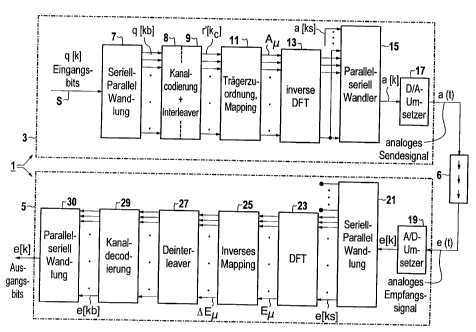
Fig. 1 shows a block diagram of a system for information
transmission 1 (called the system 1 in the following text),
which will initially be explained roughly and in schematic
form. In this case, the reference symbols 3 and 5 denote,
respectively, the devices at the transmitter end and at the
receiver end of the system 1. Specifically, 3 denotes a
device for producing a transmission signal and may, at least,
be part of a transmitter. In an analogous manner to this, 5
represents a receiving device, or at least a part of it. The
reference symbol 6 denotes a transmission path.
The input of the system 1 is supplied, as the input signal S,
with information intended for transmission. In the present
case, it is assumed that, by way of example, this is digital
information in the form of serial input bits, which may also
be referred to as source symbols q[k]. The serial input
signal S is then first of all supplied to a serial/parallel
converter 7, so that a parallel signal is produced, with
blocks as source symbols q[kb]. If the input signal S is
already in parallel form, then it may be possible to dispense
with the serial/parallel converter 7.
This is followed by a channel coder 8, which produces a block
of code symbols r[kc], which is supplied to an error-coding or
interleaving module (called an interleaver 9 in the following
text). The interleaver 9 produces a block of resorted or
interleaved code symbols r'[kc], which have a maximum signal
spacing in the signal space.
A mapping module 11 is connected downstream of the interleaver
9, in which mapping module 11 the code symbols r'[kc] are
assigned to a signal space using the PSK or QAM method. These
methods are known per se from the prior art referred to above.
A block of signal points A is then available as the output
signal.
This is followed by a module for carrier modulation 13, in
which each subcarrier of the multicarrier transmission method
is pulse-amplitude-modulated (PAM). Inverse discrete Fourier
transformation (IDFT) is used for this purpose. The resultant
so-called channel symbols a[ks] are supplied to a
parallel/serial converter 15, which produces a time-discrete
transmission sequence a[k].
CA 02266372 1999-03-18
An element (which is not shown in any more detail) for
producing a transmission pause between successive blocks can
be provided in or adjacent to the module for carrier
modulation 13. A preamble may possibly also be added to each
block in this case. This will be described specifically
further below.
The transmission sequence a[k] is converted by a downstream
digital/analog converter 17 into an analog transmission signal
a(t), which then - possibly with the interposition of further
technical means which are not shown in any more detail - , for
example an antenna, can be passed to the transmission path 6.
Since the system 1 can be used for widely differing
applications, any other required transmission paths are also
feasible. The transmission path 6 may be configured, for
example, to be cable-free or wire-free, in particular as a
radio link or optical link. An optical transmission medium,
in particular an optical conductor, is also suitable. As a
further option, a power cable, non-power cable or a
corresponding network may also be used. A link similar to an
EIB bus is particularly suitable for this purpose, or else a
power distribution network which can be used for many types of
data transmissions, in particular for meter reading for the
purposes of an energy management system. The advantages of
low-error transmission are particularly important in this
case.
The procedure at the receiver end is the inverse of that at
the transmitter end, in order to recover the original input
signal S. The transmission signal a(t) which is received by
the receiving device 5, called the received signal e(t) in the
following text, is initially supplied to an analog/digital
converter 19, downstream from which a serial/parallel
converter 21 is connected, by means of which channel symbols
e(ks) are produced.
These channel symbols e(ks) are supplied to a downstream
demodulator 23, which works on the basis of discrete Fourier
transformation. The transmission pause (guard interval) which
may have been inserted can also be removed here. The
subcarrier coefficients E then become the output signal.
This is followed, in the same way as at the transmitter end,
by a module 25 for inverse mapping, an error-decoding and/or
deinterleaving module 27 (also called a deinterleaver) and a
channel decoder 29. If the intention is that the original
signal to be demodulated is to be output as a serial signal,
then this may also be followed by a parallel/serial converter
30.
CA 02266372 1999-03-18
The following text provides a further description of details
and specific features of the preferred embodiment of the
system and of the methods used in it. Other terminology and
designations that are known from practice but differ from
those above may also be used in this case, in order not to
constrict the general character of the system.
The system is based on a DMT (discrete multitone method) in
conjunction with DPSK (difference phase shift keying)
modulation. The basic structure of the system 1 as shown in
Fig. 1 corresponds to a conventional OFDM system. This is
based on serial/parallel conversion of the source symbols
q[kb]. A block of source symbols is then channel-coded.
Convolution coding or block coding is particularly suitable
for this purpose, as is described, for example, in Proakis,
John G.: Digital Communications, McGraw-Hill New York 1995,
3rd edition. This results in a block of code symbols r[kc],
which are resorted or interleaved by the interleaver 9, thus
producing r'[kc]. The block of code symbols r'[kc] is then
assigned to a block of signal points A=[A1 A AM], using
a PSK scheme, in the signal space (mapping).
Each subcarrier is now phase-amplitude modulated with the
associated amplitude coefficient Am. This is done using an
inverse discrete Fourier transformation (IDFT). Splitting
between the M sub-channels is carried out by inverse discrete
Fourier transformation (IDFT) in accordance with the following
relationship, in which j denotes the square root of -1.
a[k] = I DFTA }= 1 ~ A ej ~( -1)=k
M =1
where: K = result index, M = transformation length, m
sequential index and A = amplitude.
A correction factor 1/M is required in this definition of DFT,
owing to Parseval's equation. This signal synthesis is
carried out efficiently using fast Fourier transformation
(FFT) algorithms, with M being a power of two. The 2M base
functions for the 2M-dimensional signal space are given by the
base functions for discrete Fourier transformation in
accordance with the relationship
+i 2R JI k r l l
e M =cos~ ~ =~c=kJ+j=sin ~ ~ = =k
for which reason they are also orthogonal. Each complex
subcarrier coefficient A is a vector in the 2-dimensional
signal space of the -th subcarrier.
~
CA 02266372 1999-03-18
The channel symbols a[ks] resulting from this have added to
them a periodic continuation or transmission pause at the
start of each block (the so-called guard interval). After
subsequent parallel/serial conversion, this results in a time-
discrete transmission sequence a[k]. Provided the guard
interval is chosen to be sufficiently long, successive blocks
are transmitted without any pulse interference. With regard
to the guard interval, see also Benndorf, Jens et al:
Angepabte Signale fur Kanale mit Intersymbolinterferenzen,
Archiv der elektrischen 'Obertragung [Adapted signals for
channels with intersymbol interference, Electrical
Transmission Archive] Vol. 46, 1992, pages 409 to 414. The
analog transmission signal a(t) is produced simply by D/A
conversion of the transmission sequence a[k].
After transmission over the transmission channel 6, the
received transmission signal is in the form of analog received
signal e(t). Bandpass signals are, as a rule, treated as
equivalent low-pass signals. In practice, the signal
therefore has to be low-pass filtered in order to limit the
noise bandwidth and to suppress any aliasing components.
After A/D conversion, the samples are converted from serial to
parallel form using the channel symbol clock T, and the guard
interval is removed.
The amplitude coefficients of the subcarriers Ei are obtained
using discrete Fourier transformation (DTF). In this case,
the DFT uses 2M parallel correlators, whose output is the
received amplitude coefficients Em of the subcarriers,
corresponding to M sub-channels with 2-dimensional
transmission signals. If the channel is modelled by a non-
recursive filter with an impulse response h[k] and white
random noise n[k] is added to this (in this context, Fig. 2
shows a time-discrete channel model), then this results in the
received values E for the subcarriers Ei in accordance with
the following equation (provided the guard interval is
sufficiently long):
E = X ' A + N
where
M-1h[k1ejMk(-1)=Hf= 2
-l
k=O J ( M = T
and
~G
CA 02266372 1999-03-18
M-1 -7? 'k'( -1)
N =Zn[k]=e "'
k=0
The transmission can thus be regarded as a weighting of the
subcarrier coefficients A with the 1 , as is shown in Fig. 2.
The convolution of discrete channel symbols a[k] with the
discrete channel impulse response h[k] appears, in terms of
the amplitude coefficients of the subcarriers, as a complex
(time-invariant) weighting of the transmission carrier values
with the samples of the channel transfer function.
The assignment of the subcarrier values in signal space to
binary symbols is carried out using inverse mapping.
Subsequent decoding produces the estimated, binary source
symbols. The input values to the decoder may be decision bits
(quantized to 1 bit) or soft-decision values (quantized to a
number of bits).
The preferred procedure for the system 1 comprises a specific
combination of channel coding, interleaver and specific
carrier allocation. The subcarrier allocation is now
determined using the following method:
The block of code symbols r'[kc] is assigned to a block of
signal points DA=[DA2 DA DAMO] using a PSK scheme
(mapping), in which only MO of M are used rather than all the
subcarriers (unused subcarriers are set to zero).
Examples of 4-PSK with:
Input bits DA
00 1
j
11 -j
01 -j
Each signal point DA is accordingly assigned to one of the MO
sub-channels (subcarriers) used, with one sub-channel being
reserved. Assignment to the subcarriers is now carried out
using differential coding along the subcarriers in the
frequency domain, that is to say not in the time domain as is
normal with known DPSK modulation. The allocation of the
subcarriers A=[Al A AM] results from the DA in
accordance with the following equation:
~I, ' Ai,-, p = 2(1~1~10
A 0 ,u = Ma + 1(1*
where IAf,I,IDA, 1:=1
CA 02266372 1999-03-18
where Al is set to be constant, and is thus used as a
reference.
The received subcarrier values E are differentially
demodulated, resulting in differentiation in the subcarrier
direction. If one considers interference-free transmission,
then:
AE - E = E
.
= Hi, . Al, = Hf,_, = A,,--
IH,l I = IHI1-I I = AAI,
If Af is small, then
_27r_ 2
~f T M=T
(that is to say M 1), the estimate
a', - af,_, 1
is highly valid and, to a good approximation:
;:t~ IH,, I = JH,,_, I . AA,,
In this case, H* and A* are the complex conjugates of H and A,
respectively.
The differentiation thus results in phase distortion
correction. This corresponds to the relevant distortion
correction for PSK modulation. No amplitude distortion
correction is required, but can easily be implemented as an
option, by complex division. The error, which is generally
small, in the phase distortion correction can be compensated
for by simple channel coding. A major advantage of the above
procedure is that phase distortion correction can be carried
out even though no explicit distortion correction is provided.
In addition, differential coding in the frequency domain
allows each block to be decoded separately, which is
impossible with coding in the time domain. The phase error of
the amplitude coefficients thus depends only on the
interference signal, and to only a minor extent on the phase
distortion in the transmission channel.
The system 1 uses block synchronization. In general, the
transmitter and receiver in a transmission system have to be
1~
CA 02266372 1999-03-18
synchronized to one another. In the present case, sampling
phase synchronization or detection of the block start is
sufficient. In practice, a sampling phase error causes
rising, that is to say linear, phase distortion of the
subcarriers. This follows from the translation theorem for
discrete Fourier transformation
2,N
DFT {v[k - v]} = e -""' = DFT {v[k]j
The effects of this phase error can substantially be
compensated for by the differentiation in the receiver.
Together with channel coding, sampling phase errors of up to
5T (T=sampling rate) - this corresponds to 500% of the
channel symbol clock rate, or 2% of the block length without
a guard interval - do not lead to any significant effects on
the bit error rate. The differential coding in the carrier
direction thus saves phase distortion correction, as well as
complex synchronization methods, by means of a very simple
modulation method.
The minor requirements for phase synchronization permit a
simple synchronization method to be used. To this end, the
transmission sequence of a block has a transmission pause and
a preamble added to it. Fig. 3 shows such a transmission
sequence a[k]. The detection of the preamble, and thus the
phase synchronization, are carried out at the receiver end in
three steps:
- correlation in the receiver,
- possible calculation of the gradient of the magnitude
values, and
- threshold value decision.
CA 02266372 1999-03-18
Simulations have shown that this allows an accuracy of T to
be achieved. The tolerances are thus not exhausted. Loss
from synchronization is in this case minimal. The method can
easily be integrated in a digital module, since correlation
and gradient calculation can be produced as an FIR filter
(finite impulse response). The filter coefficients for the
correlation filter hcor[k] result from the transmitted
preamble sequence hsync[k] as an associated single-matched
filter, in accordance with the relationship:
h.. [k]= h~õc ~ kl=
Suitable preamble sequences include, for example, Barker
sequences, Lindner sequences or Lehmann sequences (see, for
example, Klaus Lehmann: Entwurf von Filterstrukturen zur
Erzeugung mehrstufiger Codes mit Barker-Autokorrelations-
Eigenschaften [Design of filter structures for producing
multistage codes with Barker autocorrelation characteristics],
Archiv fi,ir Elektronik und Ubertragungstechnik [Archive for
Electroncis and Transmission Technology] Volume 33, 1979 pages
190-192). The important factor in this case is the aperiodic
autocorrelation function of the sequence (see also LUke, Hans
Dieter: Korrelationssignale [Correlation signals], Springer
Berlin 1992). This should have a pulsed character, as shown
in Fig. 4. Fig. 4 shows an aperiodic autocorrelation function
(ACF) for the 7th Barker sequence. There is no need for any
limitation to binary preamble sequences.
Any gradient calculation which may be carried out in this case
relates to the gradient of a straight line passing through a
limited number of correlation values Cv, using linear
regression methods. Linear regression minimizes the sum of
the squares of the errors between the points on the straight
line and the correlation values. The duration of the time
window, and thus the number of points which are interpolated
by a straight line, in this case depends on the application or
channel. Such a gradient calculation can likewise be carried
out using an FIR filter.
Fig. 5 shows one example of a gradient calculation using
linear regression based on 10 support points (n=0 to 9). In
this case, a straight line is passed through 10 points, in
order to illustrate the procedure. Alternatively, if the ACF
is suitable, a direct threshold value decision may also be
used.
Two carrier oscillation parameters have to be investigated for
carrier synchronization: the effects of a carrier phase error
and of a carrier frequency offset. If a carrier phase error
Ae is present, this means that the phase of all the
IN
CA 02266372 1999-03-18
subcarriers is shifted by the magnitude of the phase error De
in accordance with the following relationships.
vNF IkJ- vHF LkJ' e-!(21rk+Ac)
vNF [k] - vHF IkJ' e _j2,rk+Ae
After differential demodulation, this error is completely
eliminated. There is therefore no need for carrier phase
synchronization.
On the other hand, carrier frequency synchronization is always
worthwhile. In this case, simulations have shown that a
frequency offset of 10-5 with respect to the sampling frequency
(in baseband, that is to say at the channel symbol clock rate)
has virtually no influence. Greater discrepancies cause rapid
degradation of the system. The requirements for frequency
accuracy in the method can be satisfied without any problems
using means based on the current prior art.
For digital data transmission, the new system and its methods
and devices result in high bandwidth efficiency and a low bit
or message error probability, with method steps and
interrelationships being combined with one another and
complementing one another in a particularly advantageous
manner. The invention provides digital data transmission with
coding and decoding in which, in contrast to the prior art,
there is no need for carrier synchronization or clock
synchronization. Only block synchronization is still
required, and this is achieved in a simple manner.
The advantageous modulation in conjunction with suitable
coding achieves, for example, a bandwidth efficiency of better
than 1 bit/s/Hz for a "Four-phase signal", as is shown in Fig.
6 (signal constellation for 4-PSK). Depending on the required
data transmission rate, bit error probability and available
transmission bandwidth, the described method can be
implemented flexibly and without any problems by a simple
combination of special hardware, microprocessors, digital
signal processors or ASICs which need to be specially
developed. The system has already been successfully tested by
simulation using specially configured hardware (DSP with PC).