Note: Descriptions are shown in the official language in which they were submitted.
CA 02270224 2004-11-18
1
HYDRAULIC IMPACT TOOL FOR A WELL
The present invention relates to a hydraulic impact tool
for use in a well, such as an oil or gas well, in
particular to apply impact energy to a stuck object in
order to get the object loose or break it.
Impact tools are often used in connection with operations,
in which valves, measuring equipment and other equipment is
to be anchored down in a well. An impact tool is attached
as an extension of a pipe string, for example a drill
string or coiled tubing, and equipment to be placed in the
well is attached to the free end of the impact tool. The
impact tool has a channel extending therethrough, so that
fluid may pass. The equipment to be set in the well, may be
provided with grippers, resilient lugs or other things
which engage grooves or seat surfaces provided in the wall
of the well. To ensure that the equipment does not become
detached, it is often provided with a locking device which
is activated through the shearing of a shear pin. In some
cases the pipe string cannot transfer sufficient mechanical
force to break the shear pins, and the shear pins may then
be broken by means of an impact tool. Also, the impact
CA 02270224 1999-04-29
WO 98119041 PCT/N097/00281
2
tool is often provided purely as a precaution to make
it possible to get the equipment loose in case it
should get stuck.
In a hydraulic impact tool a movable, maybe sleeve-
s shaped hammer is biased towards a stop by means of an
outer spring. A stroke is made by displacing the hammer
from the stop, and then let the pre-tensioned spring
drive the hammer back to the stop.
The hammer has a hydraulic piston arranged thereto,
provided with a through passage in which a valve is
provided. The valve is normally open, so that fluid may
pass through the piston. By activating the valve and
closing the through passage, the piston is displaced,
and thereby the hammer is displaced from the stop when
pressurized fluid is applied to it. At the same time
the spring is further tensioned because of the movement
of the hammer.
As the hammer reaches an end position, the valve is
opened, so that fluid again may flow through the pis-
ton. The hydraulic force against the piston then
quickly drops, and the spring drives the hammer (with
the piston) back towards the stop. The valve is acti-
vated and then again closes the through passage in the
piston, and the process is repeated.
It is known to use a spring, which can be prestressed
from outside, to drive the hammer. Further, it is known
to arrange said spring so, that it may be prestressed
either through pulling at the pipe string in the direc-
tion away from the impact tool, or through pushing the
pipe string in the direction towards the impact tool.
Applied to an impact tool in a vertical position, the
CA 02270224 1999-04-29
WO 98/19041 PCT/N097/00281
3
impact tool may then provide respectively upward and
downward strokes, as the impact tool may comprise two
separate valve mechanisms for upward and downward
strokes respectively. Such impact tools are generally
said to be double-acting. The magnitude of the impact
force is changed by varying the prestressing of the
spring.
It is common for said hydraulic valves activating the
impact tool, to be influenced by the biasing of the
spring. If the spring is in a neutral position, fluid
may be pumped through the pipe string without the im-
pact tool being activated. By applying a biasing to the
spring, upwards or downwards, as mentioned, the impact
tool is activated by a sealing body being brought to
seal against through-put of fluid. This results in a
pressure build-up, and the resulting hydraulic force
displaces the hammer to a stroke start position.
In known impact tools the valve in the piston is acti-
vated, so that the through passage is closed by the
hammer being carried to the start position towards the
stop. Load of equipment hanging from the impact tool is
often sufficient for exactly this to happen. This leads
to fluid circulation through the pipe string being im-
possible as the impact tool is being inserted or with-
drawn from the well without activating the impact tool.
If circulation of long duration is required, said
equipment may be damaged by the impact effect. The hy-
draulic parts of the impact tool, such as piston and
valve elements, wear in operation, and will have to be
3o replaced at regular intervals. In a long-lasting opera-
tion, in which fluid circulation is required, parts of
the impact tool may be significantly worn before the
CA 02270224 1999-04-29
WO 98/19041 PCTlN097/00281
4
impact tool will be put into operation, which may lead
to a reduced impact effect and functional error.
The object of the invention is to provide a hydraulic
impact tool where it is possible to circulate fluid,
e.g. drill fluid, therethrough, without the impact tool
being activated as the spring is being prestressed.
The object is reached through characteristics as stated
in the following description and subsequent claims.
An impact tool according to the invention comprises hy-
draulic valve devices, which are arranged, in a manner
known in itself, to close a through passage of a pis-
ton, as described, but in which the valve device only
can be activated, when the flow rate of the fluid being
circulated through the pipe string, exceeds a predeter-
mined value.
The invention is described in the following through a
non-limiting example of an embodiment of a double-
acting impact tool, with reference to the accompanying
drawings, in which:
2o Fig. 1 shows a sectional side view of an upper and up-
ward working part of an impact tool in initial posi-
tion, referred to a vertical position of use;
Fig. 2 shows the upward working part ready to strike;
Fig. 3 shows the upward working part ready to strike,
the striking movement having started;
CA 02270224 1999-04-29
WO 98/19041 PCT/N097/00281
Fig. 4 is a sectional side view of a lower and downward
working part of the impact tool in initial position;
Fig. 5 shows the downward working part ready to strike;
Fig. 6 shows the downward working part ready to strike,
5 the striking movement having started.
Fig. 7 is a sectional top plan view of an upper end
piece;
Fig. 8 is a sectional side view of an upper piston;
Fig. 9 is a top plan view of the piston in fig. 8;
Fig. 10 is a sectional side view of an upper slide;
Fig. 11 is a top plan view of the slide in fig. 10;
Fig. 12 is a sectional side view of a sleeve-shaped
body enclosing a lower slide;
Fig. 13 is a top view of the sleeve-shaped body and the
slide in fig. 12.
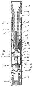
In fig. 1 the reference numeral 1, applied to a verti-
cal position of use, indicates an upper tubular hous-
ing, which by its lower end is extended by a lower tu-
bular housing 2 by means of an intermediate connection
3, which is provided with a through channel 4, see
Figs. 1 and 4.
CA 02270224 1999-04-29
WO 98/19041 PCT/N097/00281
6
The upper housing 1 is provided at its lower end with
an internally threaded portion which engages complemen-
tary external threads at upper end of the connection 3.
Sealing means, not shown, are provided, so that a pres-
s sure-tight connection is formed between the upper hous-
ing 1 and the connection 3.
The lower housing 2 is provided at its upper end with
an internally threaded portion, which engages comple-
mentary threads at the lower end of the connection 3,
and sealing means, not shown, are provided, so that a
pressure-tight connection is formed between the connec-
tion 3 and the lower housing 2. The upper and the lower
housings 1, 2 may thus be threadingly connected to a
respective end of the connection 3, to form a continu-
ous housing for the impact tool.
Fluid may pass from the upper housing 1 into the lower
housing 2 through channel 4 of the connection 3.
The upper housing 1 is extended at its upper end by an
upper end sleeve 5 which is screwed into the upper
housing 1, the upper housing 1 being provided with an
internally threaded portion 6 which engages complemen-
tary external threads on the end sleeve 5. Between the
upper housing 1 and the upper end sleeve 5 is provided
a first sealing 7.
The upper end sleeve 5 encloses an upper end piece 8
projecting through both ends of the end sleeve 5, and
arranged so as to permit axial displacement thereof
within the sleeve 5. The displaceable end piece 8 con-
stitutes an upward acting hammer of the impact tool,
and the end piece 8 is provided with an external impact
ring 9 which is arranged to abut an internal shoulder
CA 02270224 1999-04-29
WO 98/19041 PCT/N097/00281
7
of the end sleeve 5. A second seal 11 at the lower
end of the upper end sleeve 5 slidingly seals against
the end piece 8 below the impact ring 9. Thus, in the
end sleeve 5, between the seal 11 and the shoulder 10,
5 is formed a portion of larger inner diameter than in.
the rest of the end sleeve 5. To allow the end piece 8
to be mounted in the end sleeve 5, the end sleeve 5
must be divided. A skilled person will be able to suit-
ably divide the end sleeve 5 in several ways. Division
10 into two pieces in a plane through the main axis of the
end sleeve 5 has proved to work well. Division of the
upper end sleeve 5 is not shown. Externally, above the
impact ring 9, the end piece 8 is provided with notches
which cut through the impact ring 9, so that fluid may
pass from below the impact ring 9 to above, further up-
ward between the end piece 8 and the end sleeve 5, fur-
ther out of the impact tool through ports 13 at the up-
per end of the end sleeve 5.
In a known manner, the upper end piece 8 is provided at
its upper end with an internally tapered threaded por-
tion 14 for connection to a not shown pipe string,
which is provided, in a known manner, with a not shown
spring device arranged to be prestressed and provide
impact energy for the impact tool.
The upper end piece 8 is provided with a bore 15 to al-
low a fluid, typically a drill fluid, to flow through
the end piece 8 into the upper housing 1.
To the lower end of the upper end sleeve 5 is attached
an upper piston 16 which slidingly seals outwards
against the upper housing 1 by means of a seal 17. The
piston 16 is provided with an internally threaded por-
tion 18 which engages complementary external threads at
CA 02270224 1999-04-29
WO 98/19041 PCT/N097/00281
8
the lower end portion of the upper end piece 8. In the
upper piston 16, above the seal 17, are provided sev-
eral grooves 19, so that fluid may flow through the
bore 15 of the upper end piece 8, out through said
grooves I9. The pressure of the fluid may thus affect
the whole surface area of the piston 16 above the seal
17.
In the piston 16 is provided a through channel 20,
which at its upper outlet is provided with a seat sur-
face 21, see Figs. 1, 8 and 9.
An upper sealing body 22 comprises a stem which is pro-
vided, at its upper end, with a head 23. The head 23 is
arranged to seal against the seat surface 21 of the
piston 16. The stem 24 of the sealing body 22 extends
within the channel 20 of the piston 16, through the
piston 16 to somewhat below the underside of the piston
16.
The stem 24 of the sealing body 22 is supported axially
displaceable in an upper slide 25, which may be moved
axially in the upper housing 1. The upper slide 25 is
provided with longitudinal external grooves 26, so that
fluid may pass on the outside of the slide 25, see
Figs. 10 and 11.
A spring 27, acting between the sealing body 22 and the
slide 25, lifts the sealing body 22 to an upper end po-
sition, to create a clearance between the head 23 and
the seat surface 21.
Fluid may flow through the bore 15 of the upper end
piece 8, into the piston 16 and through the channel 20,
CA 02270224 1999-04-29
WO 98/19041 PCT/N097/00281
9
there being a clearance between the channel 20 and the
stem 24 of the sealing body 22, and further, through
the grooves 26, past the upper slide 25.
The upper slide 25 is kept in an upper end position
against an internal shoulder 28 of the upper housing 1
by an upper slide spring 29 acting between the upper
slide 25 and the upper end of the connection 3. The
stem 24 of the sealing body 22 is provided with a col-
lar 30 arranged to abut the upper side of the slide 25.
In the lower housing 2 are provided parts complementary
to those mentioned above. The parts in the lower hous-
ing 2 are active in downward strokes.
At the lower end of the lower housing 2 is provided a
lower end sleeve 31, see Fig. 4. The lower housing 2 is
provided at its lower end with an internally threaded
portion 32 which engages complementary external threads
on the lower end sleeve 31. Sealing means, which are
not shown, provide a pressure tight connection between
the lower housing 2 and the lower end sleeve 31.
The lower end sleeve 31 encloses an axially displace-
able, tubular lower end piece 33 with a bore 34 extend-
ing therethrough, so that fluid may flow from the lower
housing 2 out through the lower end piece 33. The lower
end piece 33 is provided at its lower end with exter-
nal, tapering threads 35, which are complementary to
the internal tapering threads 14 of the upper end piece
8, for connecting to a tool, pipe string or other ob-
ject.
CA 02270224 1999-04-29
WO 98/19041 PCT/N097/00281
The lower end piece 33 is provided with an external an-
nular impact surface 36. In downward strokes, the lower
end piece 33 is stationary, while the other parts of
the impact tool is driven in a downward direction, so
5 that the lower end of the lower end sleeve 31 hits the
impact surface 36. This will be explained in more de-
tail later.
To the upper end of the lower end piece 33 is attached
a sleeve-shaped body 37, which is provided at its lower
10 end with an internally threaded portion 38 engaging
complementary external threads at the upper end of the
lower end piece 33. Side ports 39 in the lower end
piece 33 connect the bore 34 to an annulus 40 between
the lower housing 2 and the lower end piece 33. The an-
nulus 40 is defined in the longitudinal direction by
the lower end sleeve 31 and the sleeve-shaped body 37.
When the lower end piece 33 is displaced in relation to
the lower housing 2 and the lower end sleeve 31, the
length of the annulus 40 will change.
A lower piston 41 rests by its underside on an upper
end of the sleeve-shaped body 37. Externally, the lower
piston 41 is provided with a fourth seal 42 which slid-
ingly seals outwards against the lower housing 2. In
the same manner as the upper piston 16, the lower pis-
ton 41 is provided with a through channel 43 which is
provided with a seat surface 44 at its upper outlet.
A lower sealing body 45 comprises, in the same way as
the upper sealing body 22, a head 46 arranged to seal
against the seat surface 44 of the lower piston 41.
Likewise, the lower sealing body 45 comprises a stem 47
which extends within the channel 43 through the lower
piston to a lower slide 48, in which the sealing body
CA 02270224 1999-04-29
WO 98/19041 PCT/N097/00281
11
45 is displaceably supported. The lower slide 48 may be
moved axially within the lower housing 2. A lower
spring 49 acting between the lower sealing body 45 and
the lower slide 48, retains the sealing body 45 in an
upper position, so that there is a clearance between
the head 46 and the seat surface 44.
The stem 47 of the lower sealing body 45 is provided
with a collar 51 which is arranged to abut the upper
side of the slide 48. As the upper slide 25, the lower
slide 48 is correspondingly provided with longitudinal
external grooves, so that fluid may pass on the outside
of the slide 48.
A lower slide spring 50 provided in the annulus between
the sleeve-shaped body 37 and the lower housing 2, acts
between the upper side of an internal collar 52 of the
housing 2, and the underside of the lower slide 48. The
lower slide spring 50 retains the lower slide 48 in an
upper starting position.
As mentioned, the lower slide 48 is provided with ex-
ternal grooves, so that the body material between said
grooves forms radial fins 53. The lower slide 48 is en-
closed by the upper part of the sleeve-shaped body 37.
The wall of said upper part of the sleeve-shaped body
37 is provided with slots or grooves 54, through which
the fins 53 of the slide 48 project, see Figs. 12 and
13. The grooves 54 are of sufficient length to enable
displacement of the slide 48 over a downward distance
within the sleeve-shaped body 37.
The lower slide spring 50 acts against the underside of
the fins 53, through a retaining ring 55, see Fig. 4.
CA 02270224 1999-04-29
WO 98/19041 PCT/N097/00281
12
The operation of the impact tool will be described in
the following, and first upward strokes will be de-
scribed with reference to Figs. 1 - 3.
In the initial position, as shown in Fig. 1, the upper
end piece 8 is retained by an upward acting force from
a not shown prestressed spring, in an initial position,
in which the impact ring 9 bears against the shoulder
10.
Fluid is circulated from the surface through the bore
15 of the upper end piece, past the head 23 of the up-
per sealing body 22, through the channel 20 of the up-
per piston 16, past the upper slide 25 to the connec-
tion 3. The fluid passes the connection 3 through the
channel 4 to the lower housing 2, through the lower
piston 41, past the lower slide, out through the bore
34 of the lower end piece 33, see Fig. 4. The impact
tool is idle and allows fluid to pass.
To activate the impact tool, the flow rate of the fluid
is increased, so that the friction of the fluid against
the upper sealing body 22 results in a downward force
which displaces the sealing body 22 against the force
of the spring 27, until the head 23 of the sealing body
22 lands on the seat surface 21 of the upper piston 16.
The head 23 thus closes the channel 20 for through-put
of fluid. The now tight piston 16 is driven downwards
within the upper housing 1 by the force, applied by the
fluid pressure to the piston 16 and the head 23 of the
sealing body 22. The piston 16 pulls the upper end
piece 8 downward.
The collar 30 of the stem 24 of the sealing body 22
lands on the upper slide 25. The force of the hydraulic
CA 02270224 1999-04-29
WO 98/19041 PCT/N097/00281
13
pressure acting on the upper side of the head 23 of the
sealing body 22, thus drives the upper slide 25 down-
ward against the force of the upper slide spring 29, as
shown in Fig. 2.
The motion of the slide 25, tensions the slide spring
29, so that the slide spring 29 effects a constantly
increasing upward force against the slide 25 and the
sealing body 22.
If the force of the slide spring 29 exceeds the hydrau-
lic force acting on the head 23 of the sealing body 22,
the slide spring will lift the head 23 clear of the
seat surface 21 in the piston 16. Alternatively, the
slide 25 will reach a lower end position in abutting
the connection 3, or by the slide spring 29 not being
further compressible. The hydraulic force acting on the
piston 16, will force the piston 16 further downwards,
and a clearance is created between the head 23 of the
sealing body 22 and the seat surface 21 of the piston
16.
Fluid will immediately pass through the upper piston
16, resulting in a quick fluid pressure drop above the
piston 16. The hydraulic force against the sealing body
22 and the piston 16 is correspondingly reduced. The
slide spring 29 drives the slide 25 and the sealing
body 22 back towards their initial positions, see Fig.
3.
The force of said, not shown, prestressed spring pulls
the upper end piece 8 and the piston 16 towards the
initial position, and the impact ring 9 hits the inter-
nal shoulder 10 of the upper end sleeve 5, whereby an
upward stroke is created. Friction of the flowing fluid
CA 02270224 1999-04-29
WO 98/19041 PCT/N097/00281
14
will again carry the head of the sealing body 22 into
abutment against the seat surface 21 of the piston 16,
and the process is repeated.
To achieve downward strokes, a downward spring force
from a prestressed spring, not shown, is applied to the
tool. The upper end piece 8 and the piston 16 are then
pushed down into the upper housing 1, and the sealing
body 22 cannot close the channel 20 of the upper piston
16, even if the sealing body 22 is displaced into the
lower end position. The upper part of the impact tool,
i.e. the components located in the upper housing 1, are
idle in downward strokes.
Downward strokes will be described with reference to
Figs. 4 - 6. In the same way as for upward strokes,
fluid may pass, even if the impact tool is subjected to
a downward force from a prestressed spring. To activate
the impact tool, the operator increases the flow rate
of fluid flowing through the impact tool, as already
described.
Frictional force acting against the lower sealing body
45, displaces the sealing body 45 against the force of
the spring 49. The head 46 lands on the seat surface 44
in the lower piston 41 and closes the channel 43 for
through-put.
The fluid pressure acting on the upper side of the
lower piston 41, will lift the lower housing 2, with
the lower end sleeve 31 and the rest of the impact
tool, in relation to the lower end piece 33, as the
lower piston 41 rests on the upper end of the sleeve-
shaped body 37.
CA 02270224 1999-04-29
WO 98/19041 PCT/N097/00281
As the lower housing 2 is being lifted, the lower slide
spring 50 is compressed, see Fig. 5, in a manner corre-
sponding to that explained for the upper slide spring
29. The lower slide 48 abuts the collar 51 of the lower
5 sealing body 45, and the force of the slide spring 50
increases as the lower housing 2 is being lifted.
The upward force of the lower slide spring 50 against
the sealing body 45 will exceed the downward force of
the hydraulic pressure acting on the upper side of the
10 head 46 of the sealing body 45. Alternatively, the fins
53 of the lower slide will land on the bottom of the
grooves 54. Continued supply of pressurized fluid and
thereby lifting of the lower housing 2 will result in
the lower sealing body 45 also being lifted. Then a
15 clearance is created between the head 46 and the seat
surface 44. Fluid will immediately flow through the
lower piston 41, and the fluid pressure on the upper
side of the piston 41 quickly drops. The lower slide
spring 50 drives the lower slide 48 and the sealing
body 45 upward and back towards initial position. The
impact tool, apart from the lower end piece 33 which
is stationary, is driven downward by the prestressed
spring force, so that the lower surface of the lower
end sleeve 31 strikes against the annular impact sur-
face 36 of the lower end piece 33, whereby a downward
stroke is achieved.
If the flow rate is sufficiently great, fluid flowing
past the lower sealing body 45 will again displace the
sealing body 45 so that the head 46 bears against the
seat surface 44 in the lower piston 41, and the process
is repeated.