Note: Descriptions are shown in the official language in which they were submitted.
CA 02270324 1999-04-28
WIRELESS TERMINAL AUTOMATICALLY ALERTING USER UPON
WIRELESS TERMINAL ENTERING A SPECIFIED PHYSICAL
LOCATION
Technical Field
s This invention relates wireless telecommunication, and in
particular, to wireless terminals.
Back4round of the Invention
The utilization of personal communication service (PCS)
wireless terminals and switching systems is increasing for office buildings,
to large retail stores, hospitals, etc. The capability of being able to
communicate with employees where ever they may be in a facility has
proven to be worth the cost of the installation of PCS systems. Within
office buildings where the employees work the same set of hours, it is
necessary to assign to each employee their own PCS wireless terminal.
is However, within large retail stores and hospitals where multiple shifts are
worked during the day, it is sufficient to have a number of PCS wireless
terminals equal to the number of employees on a given shift. The sharing
of PCS terminals in this manner greatly reduces the cost of installing a
PCS system.
2o Problems have arisen because of the small size of the PCS
terminals, and the fact that employees become accustomed to having the
PCS terminal on their person. The end result is that an employee leaving
for the day has a reasonable probability of leaving the facility with the PCS
terminal; thus, leaving another employee on the next shift without a PCS
2s terminal. In general, the problem is not so much that the employees are
trying to steal the PCS terminals, but rather that they are simply forgetting
to turn the PCS terminal in at the end of their shift.
CA 02270324 1999-04-28
- 2-
What is needed is a procedure and mechanism whereby the
employees will be alerted if they attempt to leave the facility with a PCS
terminal.
Summary of the Invention
s The preceding problem is solved and a technical advance is
achieved by an apparatus and method that allows the detection of a
wireless terminal leaving a facility by a wireless switching system.
Advantageously, in a first embodiment, a base station is assigned to each
exit from the facility. The base station uses a directional antenna which
io only communicates with wireless terminals within the exit area. When a
wireless terminal enters the exit area and registers on the base station,
the base station transmits the registration information to a wireless
switching system that immediately places a telephone call to the user of
the wireless terminal to inform them that they have not turned in their
is wireless terminal.
Advantageously, in a second embodiment of the invention, a
transmission signal separate from the frequencies utilized for voice and
data communication by the wireless switching system is utilized to alert
the wireless terminal to the fact that the wireless terminal is in an exit
2o area. The wireless terminal is responsive to this alerting to place a call
to
the wireless switching system to inform the wireless switching system of
this fact. The wireless switching system then alerts the user via the
wireless terminal. In addition, if the wireless terminal is in a standby mode
when it enters the exit area, it is responsive to the separate transmission
2s signal to power up the wireless terminal so that the wireless terminal can
alert the wireless switching system. The separate transmission signal
may be a low radio frequency, a high radio frequency, an optical
transmission, etc.
CA 02270324 2002-07-11
-3-
Advantageously, in a third embodiment of the invention, a
base station is assigned to each exit from the facility. The base station
uses a directional antenna which only communicates with wireless
terminals within the exit area. When a wireless terminal enters the exit
s area and registers on the base station, the base station performs the
normal registration operations with a wireless switching system. After the
wireless terminal is registered, the base station places a telephone call to
the user of the wireless terminal to inform them that they have not turned
in their wireless terminal.
to In accordance with one aspect of the present invention there is
provided a method of alerting wireless telephones upon the wireless
telephones entering exits from a facility where the wireless telephones
are interconnected to a wireless telecommunication switching system via
a plurality of base stations, comprising the steps of: assigning an
is individual one of the plurality of base stations to provide wireless
service
for an individual one of the exits from the facility wherein the wireless
service provided by each individual one of the plurality of base stations is
limited to an area of each of the assigned one of the exits from the
facility; determining registration of the one of the wireless telephones by a
20 one of the plurality of base stations individually assigned to the one of
the
exits from the facility; originating a telephone call to the one of the
wireless telephones by the one of the plurality of base stations via the
wireless telecommunication switching system In response to the
determination of registration of the one of the wireless telephones where
Zs the one of the plurality of base stations is the calling parley of the
telephone call; connecting the telephone call from the one of the plurality
of base stations communicated via the wireless telecommunication
switching system to the one of the wireless telephones by the one of the
plurality of base stations where the one of the plurality of base stations
CA 02270324 2002-07-11
-3a-
remains the calling party and the one of the wireless telephone is the
called party; generating an alerting message by the one of the plurality of
base stations where the one of the plurality of base stations is the
originating source of the alerting message and the alerting message
s states that a user is about to leave the facility with the one of wireless
telephones; and transmitting the alerting message to the one of the
wireless telephones via the established telephone call by the one of the
plurality of base stations where the alerting message informs the user of
the one of the wireless telephones that the user is about to leave the
to facility with the one of wireless telephones.
In accordance with another aspect of the present invention there is
provided an apparatus for alerting a wireless terminal upon the wireless
telephone entering an exit area from a facility with the wireless telephone
being provided wireless telephone service by a wireless
is telecommunication switching system having a plurality of attached base
stations, comprising: a base station for providing wireless telephone
service only for the exit area; the base station responsive to a registration
request from the wireless terminal for processing the registration request
and for originating a telephone call to the wireless telephone by the base
?o station via the wireless telecommunication switching system where the
one of the plurality of base stations is the calling party of the telephone
call; the base station further comprises means for connecting the
telephone call from the one of the plurality of base stations
communicated via the wireless telecommunication switching system to
?s the one of the wireless telephones where the one of the plurality of base
stations remains the calling party and the one of the wireless telephone is
the called party; the base station further comprises means for generating
an alerting message by the one of the plurality of base stations where the
one of the plurality of base stations is the originating source of the
CA 02270324 2002-07-11
-3b-
alerting message and the alerting message states that a user is about to
leave the facility with the one of wireless telephones; and the base station
further transmitting the alerting message to the wireless terminal via the
telephone call informing the user of the wireless telephone that the
s wireless telephone is about to leave the facility.
These and other features and advantages of the invention
will become more apparent from the following description of an illustrative
embodiment of the invention considered together with the drawing.
Brief Description of the Drawings
to FIG. 1 illustrates a system for implementing a first
embodiment of the invention;
FIG. 2 illustrates a block diagram of a wireless terminal for
use with the first embodiment of the invention;
FIG. 3 illustrates a system for implementing a second
Is embodiment of the invention;
FIG. 4 illustrates a block diagram of a wireless terminal for
use with the second embodiment of the invention;
FIG. 5 illustrates, in flow chart form, steps performed by a
wireless switching system in implementing the first embodiment of the
zo invention;
FIG. 6 illustrates, in flow chart form, steps performed by a
wireless switching system in implementing the second embodiment of the
invention;
FIG. 7 illustrates, in flow chart form, steps performed by a
2s wireless terminal in implementing the second embodiment of the
invention;
. CA 02270324 1999-04-28
- 4-
FIG. 8 illustrates, in block diagram form, a base station for
implementing the third embodiment of the invention; and
FIG. 9 illustrates, in flow chart form, steps performed by a
controller of a base station in implementing the third embodiment of the
s invention.
Detailed Description
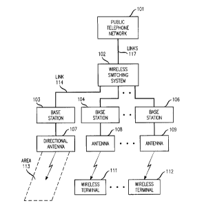
FIG. 1 illustrates a block diagram of a telephone system that
implements the first embodiment of the invention. FIG. 1 illustrates
io wireless switching system 102 communicating with public telephone
network 101 via links 117 to provide public access for wireless
terminals 111-112 via base stations 104-106 and antennas 108-109.
Wireless terminals 111-112 operate with wireless switching system 102
via base stations 104-106 using well known techniques in the art. Base
is stations 103-106 are standard base stations. Base station 103 is different
in that it utilizes a directional antenna 107 that limits its wireless
coverage
area to an area of an exit from a facility. In FIG. 1, this area is denoted
as area 113. Antennas 103-109 do not have their wireless coverage
areas inhibited. As is well known in the art, when a wireless terminal
2o moves from an area covered by one base station to an area covered by
another base station, the wireless terminal registers on the base station
whose transmission signal is the strongest. For example, when wireless
terminal 111 moves from the coverage area of base station 104 into
area 113, wireless terminal 111 will be receiving a stronger transmission
2s signal from base station 103 via directional antenna 107 then from base
station 104 via antenna 108. Wireless terminal 111 registers on base
station 103. Base station 103 is responsive to the registration of wireless
terminal 111 to implement standard registration procedures with wireless
switching system 102. Wireless switching system 102 performs the
CA 02270324 1999-04-28
- 5-
operations necessary to register wireless terminal 111 on base
station 103. In addition, wireless switching system 102 establishes a
wireless link or a telephone call to wireless terminal 111. Wireless
switching system 102 then notifies the user of wireless terminal 111 that
s the user is about to exit the facility with wireless terminal 111. This
notification to the user can simply be an auto tone via the wireless link that
wireless switching system 102 has wireless terminal 111 produce or it
may be a recorded message that is delivered to the user when the user
answers the telephone call. A voice path does not have to be set up to
io wireless terminal 111 to produce an audio warning tone if the wireless link
is used. Greater details on this operation is set forth with respect to
FIG. 2.
Wireless terminal 111 is advantageously illustrated in
greater detail in FIG. 2. The other wireless terminals are similar in design.
is Wireless set 111 implements a wireless protocol that allows wireless
terminal 111 to establish a wireless signal link with wireless switching
system 102 via base stations 103-106. One air interface that can be used
is the Japanese PHS protocol as set forth in "User-Network Interface and
Inter-Network Interface Standards for PHS", the Telecommunication
ao Technology Committee, 1995, and "Personal Handy Phone System RCR
Standard", Version 1, RCR STD-28, December 20, 1993. The message
set of the PHS protocol is similar to the ISDN message set. Overall
control of the wireless terminal is provided by control unit 201.
Units 202, 203, 206, 207, 208, and 209 provide the RF communication
2s capabilities for the wireless terminal. Elements 204, 210, and 211-214
provide the audio information received and transmitted to the user;
whereas, elements 216-218 and 205 provide the basic user interface.
Considering the following example of the operation of
wireless terminal 111. When control unit 201 via single strength
CA 02270324 1999-04-28
- 6-
monitor 202 determines that the transmission signal being received from
base station 103 is stronger than the transmission signal being received
from base station 104, control unit 201 performs the registration
procedures with base station 103. Upon detecting the registration of
s wireless terminal 111 on base station 103, wireless switching system 102
can transmit via the wireless signal link a message which will activate
audio tranducer 217 and also may send a message to indicate on
display 216 that wireless handset 111 is being carried out of the facility.
Also, wireless switching system 102 may set up a voice telephone call to
io wireless terminal 111. When the user answers this call, wireless switching
system 102 plays a recorded message to the user utilizing
elements 204, 206, 210, 211, and 213. The voice message informs the
user that wireless terminal 111 is about to be taken out of the facility.
FIG. 3 illustrates another system having a second
is embodiment for implementing the invention. FIG. 3 illustrates wireless
switching system 302 communicating with public telephone network 301
via links 317 to provide public access for wireless terminals 311-312 via
base stations 304-306 and antennas 308-309. Wireless terminals 311-
312 operate with wireless switching system 302 via base stations 304-306
2o using well known techniques in the art. It is assumed that base
station 304 via antenna 308 provides coverage for area 313. When a
wireless terminal, such as wireless terminal 311, moves into area 313,
wireless terminal 311 receives a low frequency transmission from low
frequency transmitter 303 via directional antenna 307. Wireless
2s terminal 311 is responsive to this low frequency transmission to establish
a wireless signaling link with wireless switching system 302 via base
station 304. Note, the wireless signal link may be already established.
Over this wireless signaling link, wireless terminal 311 informs wireless
switching system 302 that it is receiving the low frequency transmission.
CA 02270324 1999-04-28
Wireless switching system 302 then alerts the user of the wireless
terminal 311 using operations previously described with respect to
FIGS. 1 and 2. One skilled in the art could readily envision that low
frequency transmitter 303 could transmit at any RF frequency or could be
s an optical transmitter with the wireless terminals having the capability of
receiving this type of transmission. Advantageously, if wireless
terminal 311 is in the standby mode, upon receiving the transmission from
low frequency transmitter 303, wireless terminal 311 is activated so as to
establish the wireless signaling link.
to Wireless terminal 311 is advantageously illustrated in
greater detail in FIG. 4. The other wireless terminals are similar in design.
Wireless set 311 implements a wireless protocol that allows wireless
terminal 311 to establish a wireless signal link with wireless switching
system 302 via base stations included in wireless switching system 302.
is One air interface that can be used is the Japanese PHS protocol as set
forth in "User-Network Interface and Inter-Network Interface Standards for
PHS", the Telecommunication Technology Committee, 1995, and
"Personal Handy Phone System RCR Standard", Version 1, RCR STD-28,
December 20, 1993. The message set of the PHS protocol is similar to
2o the ISDN message set. Overall control of the wireless terminal is provided
by control unit 401. Units 402, 403, 406, 407, 408, and 409 provide the
RF communication capabilities for the wireless terminal.
Elements 404, 410, and 411-414 provide the audio information received
and transmitted to the user; whereas, elements 416-418 and 405 provide
2s the basic user interface. The low frequency transmission from low
frequency transmitter 303 is received by low frequency receiver 418 via
antenna 419. Upon reception of the low frequency transmission, low
frequency receiver 418 transmits a control signal to control unit 401.
Control unit 401 is responsive to this signal to power up if in the standby
CA 02270324 1999-04-28
_ $_
mode and to establish a wireless signaling link with wireless switching
system 302. Once the wireless signaling link has been established,
control unit 401 transmits a message to wireless switching system 302 to
inform it that wireless terminal 311 is receiving the low frequency
s transmission. Wireless switching system 302 then alerts the user of
wireless terminal 311 using similar operations as performed by wireless
switching system 302 with wireless terminal 311.
FIG. 5 illustrates, in flow chart form, the steps performed by
wireless switching system 102 in the first embodiment of the invention.
1o Decision block 501 is responsive to an operation to determine if this
operation is a registration request from a base station located at an exit to
the facility. If the answer is no, the operation is processed in a normal
fashion by block 502 before control is transferred back to decision
block 501.
is If the operation is a registration at a base station located at
an exit, block 503 registers the wireless terminal and then transfers
control to block 504. The latter block alerts the wireless terminal either by
transmission of a message that causes an audio alerting signal in the
wireless terminal, transmission of an alphanumeric display message, or a
2o voice message transmitted via a telephone call. One skilled in the art
could readily see that all or a combination of these alerting operations
could be utilized in block 504. Block 506 then transmits a message
inquiring if the wireless terminal will be returned to the facility within a
predefined amount of time. This message can be transmitted either via
2s an alphanumeric display on the wireless terminal or as a recorded voice
message. The user of the wireless terminal then responds utilizing the
keyboard. This is done so as to allow users to temporarily leave the
facility for lunch breaks, etc. After execution of block 506, decision
block 507 determines if a message was received from the wireless
CA 02270324 1999-04-28
_ g_
terminal indicating that the wireless terminal will be returned within the
predefined amount of time. If the answer is yes, block 508 marks the
wireless terminal as having been temporarily removed before transferring
control back to decision block 508. If the answer in decision block 507 is
s a message stating no from the user or no message is received from the
user at all, control is transferred to block 509 which marks the wireless
terminal as having been removed from facility. Block 511 then alerts the
facility management to the fact that the wireless terminal has been
removed. The facility management is alerted so that the management
to can take steps to assure that there are adequate wireless terminals
available for the next shift. After execution, block 511 transfers control
back to decision block 501.
FIG. 6 illustrates, in flow chart form, the steps performed by
wireless switching system 302 in implementing the invention in
is accordance with the second embodiment. Decision block 601 determines
if a message is being received from a wireless terminal indicating that it is
in area 313. If the answer in no, control is transferred to block 602 for
normal processing. After execution of block 602, control is transferred
back to decision block 601. If the answer is yes in decision block 601,
2o control is transferred to block 604. Block 604 alerts the wireless terminal
either by transmission of a message that causes an audio alerting signal
in the wireless terminal, transmission of an alphanumeric display
message, or a voice message transmitted via a telephone call. One
skilled in the art could readily see that all or a combination of these
2s alerting operations could be utilized in block 604. Block 606 then
transmits a message inquiring if the wireless terminal will be returned to
the facility within a predefined amount of time. This message can be
transmitted either via an alphanumeric display on the wireless terminal or
as a recorded voice message. The user of the wireless terminal then
CA 02270324 1999-04-28
- 10-
responds utilizing the keyboard. This is done so as to allow users to
temporarily leave the facility for lunch breaks, etc. After execution of
block 606, decision block 607 determines if a message was received from
the wireless terminal indicating that the wireless terminal will be returned
s within the predefined amount of time. If the answer is yes, block 608
marks the wireless terminal as having been temporarily removed before
transferring control back to decision block 608. If the answer in decision
block 607 is a message stating no from the user or no message is
received from the user at all, control is transferred to block 609 which
io marks the wireless terminal as having been removed from facility.
Block 611 then alerts the facility management to the fact that the wireless
terminal has been removed. The facility management is alerted so that
the management can take steps to assure that there are adequate
wireless terminals available for the next shift. After execution, block 611
is transfers control back to decision block 601.
FIG. 7 illustrates, in flow chart form, the steps performed by
control unit 401 of FIG. 4 in implementing the second embodiment of the
invention. Decision block 701 determines if a message has been received
from wireless switching system 302 via the signaling link to produce an
ao alerting signal on audio transducer 417. If the answer is yes, block 702
produces the desired audio alert alerting signal. Note, that this can be
any audio alerting message from wireless switching system 302. If the
answer in decision block 701 is no, decision block 703 determines if a
message has been received from wireless switching system 302 to be
2s displayed on display 416. If the answer is yes, block 704 performs this
display function before transferring control back to decision block 701. If
the answer in decision block 703 is no, decision block 706 determines if a
message has been received from wireless switching system 302 that
pertains to call processing functions, e.g., call setup, disconnect, connect,
CA 02270324 1999-04-28
11-
alerting, etc. If the answer is yes in decision block 706, block 707
performs normal call processing. Note, if wireless switching system 302
chooses to alert the user by placing a telephone call to the wireless
terminal and playing a recorded message, blocks 706 and 707 perform
s these operations within the wireless terminal. If the answer in decision
block 706 is no, decision block 708 determines if a signal is being
received from low frequency receiver 418. If the answer is no, block 709
performs normal processing before returning control to decision
block 701. If the answer in decision block 708 is yes, block 711 sends a
Io message to wireless switching system 302 defining that the wireless
terminal is at an exit to the facility before transferring control back to
decision block 701.
FIG. 8 illustrates an embodiment of base station 103 of
FIG. 1 for implementing the third embodiment of the invention.
is Controller 802 communicates control information with wireless switching
system 102 via link 113 and ISDN interface 801. ISDN interface 801
communicates audio information with transceiver 803. Controller 802
controls transceiver 803. Transceiver 803 transmits and receives
transmission signals with wireless terminals via directional antenna 107.
2o FIG. 9 illustrates, in flow chart form, the steps performed by
controller 802 in implementing the third embodiment of the invention.
Decision block 901 determines if a registration request has been received
from a wireless terminal. If a registration request has not been received,
block 902 performs normal processing before returning control back to
Zs decision block 901. Block 902 would perform all normal call processing
operations of a base station which are well known in the art. If the answer
is yes in decision block 901, this means that a wireless terminal has
entered area 113 of FIG. 8 and is attempting to register. If the answer is
yes in block 901, control is transferred to block 903 which processes the
CA 02270324 1999-04-28
- 12-
registration request from the wireless terminal in the normal manner.
Block 904 then sets up a call to the wireless terminal. Note, that the call
being set up may be a voice call or simply a call that establishes a
signaling link to the wireless terminal. After execution of block 904,
s control is transferred to decision block 905. The latter decision block
determines when the call set up in block 904 has been completed to the
wireless terminal. When the call has been completed, control is
transferred to block 906 which alerts the wireless terminal to the fact that
it
is exiting the building. This alerting may be any of the methods described
io with respect to the first and second embodiments.