Note: Descriptions are shown in the official language in which they were submitted.
CA 02270399 1999-04-29
WO 98/27513 PCT/US97/23198
1
PREPAID CARD
BACKGROUND AND SUMMARY OF THE INVENTION
Debit cards (typically plastic cards the same size as a
conventional credit card but with a magnetic strip having magnetic
encoding thereon corresponding to a pre-purchased amount of
particular goods or services) are becoming increasingly popular as a
form of payment for goods and services. Such cards have advantages
to both to the purchasers and to those offering the goods and services
purchased utilizing the cards, and in some areas of commerce, such as
long distance telephone services, debit cards have had exponential
growth in the last few years.
There are many circumstances where it is desirable to offer
i5 debit cards at retail establishments. If the cards are active at the time
that they are offered for sale, then careful track must be kept by the
retail establishment of every aspect of handling the cards, and the
cards must be kept in a cash drawer or like secure area, to prevent
theft since the cards are easily concealed and can be of very high
2o value. Some commercial products have been provided for mounting
debit cards with cardboard packaging that is printed with various
graphics and indicia. The packaging may make the cards more
difficult to steal, and present them in a pleasing manner, however if
the cards are "active" while displayed in this matter the retailer still
25 takes a significant risk of high theft loss. For that reason many cards
are sold in such a way that they require activation by a retail
establishment, such as by a clerk entering a personal identification
number (PIN) in an appropriate electronic device, or swiping the card
CA 02270399 1999-04-29
WO 98/27513 PCT/US97/23198
2
through a card reader connected to a central computer for the company
offering the debit card. While a number of workable package
assemblies have been provided, most have drawbacks associated
therewith, such as requiring opening of a part of the packaging; or at
least requiring movement of parts of the packaging, before the retail
establishment can gain access to the magnetic strip on the card to
effect activation; or do not package the card in an interesting manner.
According to the present invention a debit card is provided in a
prepackaged debit card assembly which attractively, effectively, and
to interestingly packages a debit card for retail sale, including even on
display at point of purchase locations. The invention also relates to a
method of providing an active debit card at a point of purchase location
while effectively and interestingly displaying the card yet minimizing
the possibility of theft loss. According to both aspects of the present
z5 invention it is unnecessary to remove the card from its packaging to
effect activation, or to move any portion of the packaging for the card,
yet the card is securely mounted by the packaging and can be
relatively easily removed once activated.
According to one aspect of the present invention a prepackaged
2o debit card assembly is provided comprising the following components:
A debit card having a rectangular configuration with first and second
end edges and first and second side edges, a front and a back, and an
area. A magnetic strip provided on the debit card back face adjacent
and substantially parallel to the second side edge, the strip inactivate
25 but capable of being activated at the point of purchase. And a
mounting envelope for mounting the debit card while the magnetic
strip is exposed, the envelope comprising first and second panels, the
panels each having an area at least 20% larger (typically at least
200°l0
CA 02270399 1999-04-29
WO 98/27513 PCT/US97/23198
3
larger, and for point of purchase display at least 400% larger) than the
card area, the majority of the debit card sandwiched between the first
and second panels but the magnetic strip being uncovered by either of
the panels or any other packaging. The debit card is removably affixed
to at least one of the panels.
The card may be affixed to at least one of the panels by any
suitable conventional mechanism such as a wide variety of different
types of adhesive, tape, mechanical fasteners, or the like. Particularly
desirably is hot melt adhesive, with additional adhesive (either hot
~o melt or pressure sensitive or a wide variety of other types of adhesive)
provided to also hold the panels tightly in contact with each other.
The card is typically a plastic card, such as conventionally used for
debit cards and credit cards (and of that same size), while the panels
are preferably of at least primarily stiff cellulosic material, such as
~s paperboard, cardboard, or heavy weight paper sheets. Where point of
purchase display is to be provided the mounting mechanism is
associated with at least one of the panels remote from the card
magnetic strip for mounting the panels and debit card at a point of
purchase location. For example, the mounting mechanism may
2o comprise a hook-receiving opening, a metal or plastic hook, a strip of
tape, or a wide variety of other conventional mechanisms.
The first panel may have a flap portion thereof covering the card
adjacent the front face second edge, and hot melt adhesive may hold
the first panel flap portion to the card front face. Alternatively, the
2s front face of the card opposite the strip may also be uncovered by
either of the first and second panels, and/or the magnetic strip may be
disposed at a die cut in the second panel.
CA 02270399 1999-04-29
WO 98/27513 PCT/US97123198
4
The first and second panels may each have a rectangular
configuration with first and second opposite and substantially parallel
side edges and first and second opposite and substantially parallel end
edges, the side edges at least 10% longer than the end edges (and
preferably at least 25% longer). The magnetic strip may be parallel to
an adjacent second panel first side edge or parallel to and adjacent the
second panel second end edge. The first panel end edges may be longer
than the second panel end edges, and the first panel first edge
substantially aligned with the card second side edge and the card front
o face affixed to the first panel adjacent the first panel first side edge.
Alternatively, all of the side and end edges of the first and second
panels may be aligned with and affixed to each other, with a hook-
receiving opening formed in the first and second panels adjacent the
first end edges thereof.
~5 While it is preferred that a single debit card be mounted, the
envelope according to the invention may mount multiple cards. For
example, a second identical debit card may be mounted by the
envelope with the second card magnetic strip uncovered by the panels
or any other packaging. When mounted for point of purchase display
2o the first and second panels are preferably formed by folding in half a
paperboard sheet 8 1~ by 8 '~ inches to form an envelope 8 1/z inches by
4 1/4 inches. The debit card may be up to 30 mil PVC or teslin.
Graphics may be provided on the card wherever desired.
The cards and packages may also be made for cash drawer size,
25 e.g., the final panels in the package being approximately 6 inches by
2 1~ inches. If desired, the envelope may include a third panel, the
third panel disposed between the card and the second panel, and
CA 02270399 1999-04-29
WO 98/27513 PCT/US97/23198
typically affixed to the card and the first panel. In this case the
envelope area is less than three times the area of the card.
According to another aspect of the present invention a method of
providing an active debit card is utilized, the method comprising the
5 following steps: (a) Providing a rectangular configuration card with
first and second end edges and first and second side edges, a front and
a back and an area, with an inactive but activatable magnetic strip on
the card back face adjacent and substantially parallel to the second
side edge. (b) Packaging the card between first and second primarily
~o cellulosic panels of an envelope so that the majority of the area of the
card is sandwiched between the panels and affixed to at least one of
the panels, and so that the magnetic strip is uncovered by either of the
panels or any other packaging. (c) Mounting the envelope for display
at a point of purchase location. And (d) during or after purchase of the
~~ envelope, with card, activating the card so that it may be used as a
debit card by passing the card through a magnetic card reader without
removing the card from the envelope or moving any portion of the
envelope to expose the magnetic strip.
It is a primary object of the present invention to provide an
2o advantageous manner of packaging, and package, for debit cards, such
as long distance phone cards. This and other objects of the invention
will become clear from an inspection of the detailed description of the
invention and from the appended claims.
2s 1BRIEF DESCRIPTION OF THE DRAWINGS
FIGURE 1 is a front perspective view of one exemplary form of a
packaged debit card assembly according to the claimed invention;
CA 02270399 1999-04-29
WO 98127513 PCT/US97/23198
6
FIGURE 2 is a rear view of the assembly of FIGURE 1 with
portions of the second panel cut away for clarity of illustration;
FIGURE 3 is a top perspective view of an exemplary debit card
according to the present invention;
FIGURE 4 is an inside perspective view of the panel forming the
envelope of the assembly of FIGURES 1 and 2 with the panels opened
up to show the interior thereof;
to
FIGURE 5 is a rear view of the second embodiment of a
packaged debit card assembly according to the present invention;
FIGURE 6 is a rear view of a third embodiment of a packaged
15 debit card assembly according to the present invention;
FIGURE 7 is a rear view of a fourth embodiment of a packaged
debit card assembly according to the present invention;
2o FIGURE 8 is a front view of the embodiment of FIGURE 7;
FIGURE 9 is a front perspective view of another exemplary
embodiment of a prepackaged debit card assembly according to the
present invention;
FIGURE 10 is a rear perspective view of the assembly of
FIGURE 9 with a portion thereof cut away for clarity of illustration;
CA 02270399 1999-04-29
WO 98/27513 PCTIUS97/23198
7
FIGURES 11 and 12 are, respectively, opened up views of two
further embodiments of packaged debit card assemblies according to
the present invention, showing the interiors of the panels thereof; and
FIGURE 13 is a top perspective schematic view showing one
manner of the activation of a prepackaged debit card assembly
according to the present invention, the assembly actually illustrated in
FIGURE 13 being the assembly of FIGURES 9 and 10.
to DETAILED DESCRIPTION OF THE DRAWINGS
A first embodiment of a packaged debit card assembly according
to the present invention is shown generally by reference numeral 10 in
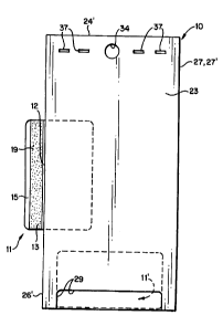
FIGURES 1 and 2. One of the elements of the assembly 10 is the debit
~s card 11, seen most clearly in FIGURES 2 and 3. The debit card 11 is
preferably plastic, e.g. 30 mil thickness PVC or teslin, and typically is
of conventional construction, e.g. rectangular configuration with first
and second end edges 12, 13, first and second side edges 14, 15, a front
i6 (FIGURE 3), a rear 17 (FIGURE 2), and an area (e.g. the area being
2o roughly between 6.5-8 square inches, e.g. the side edges 14, 15 each
about 3.3 inches, and the end edges 12, 13 each about 2.2 inches). The
debit card 11 also has a magnetic strip 19 on the back face 17 adjacent
and substantially parallel to the side edge 15. The strip 19 preferably
is inactive but capable of being activated at a point of purchase.
2s The assembly 10 also comprises a mounting envelope 21 (see
FIGURE 4 in particular) for mounting the debit card 11 while the
magnetic strip 19 is exposed. The envelope 21 comprises a first panel
22 (FIGURES 1 and 4) and a second panel 23 (FIGURES 2 and 4),
CA 02270399 2001-04-18
63423-668 (S)
8
both of which are preferably rectangular in configuration and which
may be of the same size or somewhat different sizes as will be
hereinafter further explained. Each of the panels has an area at least
20°l0 larger than the card area, and typically at least three times
larger
than the card 11 area so that the majority of the debit card lI is
sandwiched between the first and second panels but the magnetic strip
19 is uncovered by either the panels 22, 23 or any other packaging:
Each of the panels 22, 23 has first and second end edges 24, 24',
25, 26', respectively, which -- in the embodiment of FIGURES 1, 2, 4 -
io are aligned ~~ith each other; and first and second side edges 26, 26', 27,
2 7', respectively. The side edges 26, 26', 27, 2T are at least 10%
longer, and typically more than 20~%c longer, than the end edges 24, 24',
25, 25'. In the embodiment of FIGURES 1, 2 and 4 the side edges 26,
26' and 27, 2T are all of substantially the same length. As seen in
FIGURE 4, in the particular embodiment illustrated there the side
edges 27, 2 7' are a fold line of a single quadrate sheet of at least
primarily cellulose material, such as paperboard, cardboard, stiff bond
paper, or the like, folded at a score line or other fold line.
In the assembly 10 the card 11 is aced to at least one of the
2o panels 22, 23. Card 11 may be affixed by any suitable conventional
mechanism, the most desirable of which is the hot melt adhesive
illustrated schematically by blobs 30 in FIGURES 2 through 4,
because hot melt adhesive securely bonds with the plastic of the card
11 yet may be readily removed from the plastic faces 16, 17 of the card
25 I1. The hot melt adhesive 30 is preferably aced to both of the
insides of the panels 22, 23 and both of the card faces 16, 17, although
the adhesive 30 may engage only one face I6, 17. Alternative fixing
CA 02270399 1999-04-29
WO 98/27513 PCT/US97/23198
9
mechanisms may comprise other types of adhesive, tape, or mechanical
fasteners.
In the embodiment illustrated in FIGURES 1, 2, and 4, the
second panel 23 includes a die cut 29 which exposes the magnetic strip
s 19 as illustrated in FIGURE 2, the adhesive 30 holding the card 11 in
the position illustrated in FIGURE 2. The assembly 10 may also
comprise other mechanisms for holding the panels 22, 23 together
aside from the hot melt adhesive 30. For example, other strips or
patterns of adhesive 32 (see FIGURE 4) may be provided along various
0 of the edges of one or both of the panels 22, 23, such as pressure
sensitive or pressure actuatable adhesive or cohesive; or other types of
adhesive, tape, or mechanical fasteners (such as staples or rivets) may
be utilized.
When the assembly 10 is to be used for point of purchase there
1s preferably also is provided a mounting mechanism associated with at
least one of the panels 22, 23 remote from the strip 19 and mounting
the panel 22, 23 and debit card 11 at a point of purchase location. One
form that the mounting means may take is the simple opening 34
which is punched otherwise formed in both of the panels 22, 23, and
2o which may receive a conventional hook or tine 35 (see FIGURE 1) at a
retail establishment or like point of purchase location.
FIGURES 5 through 12 illustrate various other embodiments of
assemblies according to the present invention, in each case the card I1
being identically illustrated and therefore indicated by the same
2s reference numeral. In each of these other embodiments components
comparable to those in the FIGURE 1 embodiment are shown by the
same two digit reference numeral only preceded by another number.
CA 02270399 1999-04-29
WO 98/27513 PCT/ITS97/23198
Structures that are essentially identical are shown by the same
reference numeral.
FIGURE 5 is a rear view of a second embodiment of the
assembly 110 according to the present invention. In this case the only
5 differences between what is illustrated there and the FIGURES 1, 2
and 4 embodiment is the mounting of the debit card 11 so that the
majority thereof is sandwiched between the panels 22, 23 with the
stripe 19 outwardly of the envelope 21 adjacent and parallel to a side
edge 26' of the panel 23. Also, in this embodiment staples 3 r are seen
to which comprise a mechanism for holding the panels 22, 23 together.
Also, this embodiment illustrates that the assembly 110 may- include a
second (or even more) debit card, shown schematically in a dotted line
at 11' in FIGURE 5. In this case the die cut 29 is provided and the
magnetic strip of the card 11' is accessible through the cutout 29.
~5 When just the card 11 is mounted in the assembly 110 of FIGURE 5
the cutout 29 may be eliminated.
The assembly 210 of FIGURE 6 is similar to the assembly 110 of
FIGURE 5 except that the cutout 29 has been eliminated, and the end
edges 224, 225 are longer than the end edges 224' 225' so as to provide
2o the flap 39 which covers up the front face 16 of the card 11 aligned
with the strip 19, that portion-of the face 16 of the card 11 having been
exposed in the FIGURE 5 embodiment.
FIGURES 7 and 8 show another assembly 310 according to the
invention similar to that illustrated in FIGURE 1 only the
25 configuration of the mounting opening 334 is different, and the card 11
extends downwardly from the bottom edges 325, 325' of the panels
322, 323, no cutout like the cutout 29 being provided. That is, the
strip 19 -- as seen in FIGURE 7 -- is adjacent and parallel to the
CA 02270399 1999-04-29
WO 98/27513 PCT/US97/Z3198
11
bottom edge 325'. Also, in the embodiment of FIGURES 7 and 8 on the
front face of the first panel 322 -- as seen in FIGURE 8 -- a transparent
window 40 may be provided in the otherwise cellulosic material panel
322 so that the entire front face 16 of the card 11 is visible. The
transparent panel 40 may be of any suitable transparent material
such as cellophane, plastic, or the like. The transparent panel 40 may
be heat sealed, glued, affixed by tape, or affixed by mechanical
fasteners, preferably to the inside face of the panel 322.
FIGURES 9 through 12 illustrate embodiments of assemblies
1o according to the invention which are of cash drawer size (e.g. the
envelopes being approximately 6 inches by approximately 2 1~ inches)
rather than the point of purchase size of the embodiments of
FIGURES 1 through 8 (e.g. about 8 l~Z inches by about 4 1/a inches).
The assembly 410 of FIGURES 9 and 10 is very similar to the
~5 assembly 210 of FIGURE 6 except that it is devoid of a mounting hole,
and less adhesive is necessary because of the smaller components
therefore the adhesive 432 (see FIGURE 10) may be disposed along
merely the edges 424', 425' of the panel 423 to hold the panels 422, 423
together (the hot melt adhesive for holding the card 11 to the panel
20 422, 423 not seen in FIGURES 9 and 10). Also in this embodiment,
then, perforations or other lines of weakness 42 may be provided
parallel to the edges 424, 424', 425, 425'. The front face 16 of the card
11 is aligned with the strip 19 and is covered by the panel 439. When
the assembly 410 is desirably opened, the envelope is torn along the
25 perforations 42. This then means the panels 422, 423 may be easily
separated to expose the card 11.
The assembly 510 is the same as the assembly 410 except that a
third panel 44 is provided, which, during construction of the assembly
CA 02270399 1999-04-29
WO 98/Z7513 PCT/US97/23198
12
5i0, is folded over in the direction of the arrow 45 along the fold line
forming the edge interface 526' between the panels 523, 44, the panel
44 coming into face-to-face contact with the panel 522 and engaging
the adhesive 532, 30. The embodiment of FIGURE 11 will be utilized
s when the envelope of the assembly 510 is completely opened up, and it
is desired to have more area for printing of graphics or indicia.
The assembly embodiment 610 illustrated in FIGURE 12 is
~~irtually identical to that in FIGURE I1, except that for the assembly
610 the third panel 644 has a length less than the length of the panels
l0 622, 623, and the adhesive 632 thus directly holds the panels 622, 623
together after the third panel 644 has been folded in the direction of
the arrow 45 into face-to-face contact with the second panel 623.
For all of the assemblies according to the invention it is
desirable to provide indicia and graphics at a number of different
15 locations, to make the packaging attractive and to provide the desired
information. For example, as illustrated in FIGURE 1 the graphics 47
and indicia 48 may be provided on the front face of the first panel 22,
while graphics and/or indicia 49 are provided on the front face 16 of
the card 11 as illustrated in FIGURE 3. Also, the graphics 50 and
2o indicia 51 may be provided on the inside faces of the panels 523, 44 as
seen in FIGURE 11, and 623, 644 in FIGURE 12.
For all embodiments of the assemblies according to the present
invention it is desirable that the card 11 not be active until right
around the time of sale. Because the magnetic strip 19 is exposed in
25 all embodiments of the invention, and because the packaging
associated with the envelope 21 is relatively thin and normally at most
only one thickness of cellulosic material is provided on the opposite
face of the card 11 from the stripe 19, the card 11 may be activated
CA 02270399 1999-04-29
WO 98/27513 PCTIUS97/23198
13
without removing it from the packaging, or without moving any
portion of the packaging. While the card 11 may be activated in a
number of different manners, FIGURE 13 schematically illustrates
one particularly desirable manner. In this embodiment the assembly
410 is illustrated, but it is to be understood that all of the different
assemblies of FIGURES 1 through 12 are operated in the same
manner.
The assembly 410 is positioned so that the stripe 19 is in
association with the reading head of a conventional magnetic card
io reader 53 having a groove 54 therein through which a card is intended
to swiped. The reader 53 is connected by phone Iines 56 or the like to
computer center 57. When the card 11 is swiped information from
strip 19 is transmitted over the phone lines 56 to the computer center
57, which then changes its database to allow the card 11 to be used as
~5 a debit card until the predetermined amount of "money" that is
magnetically encoded thereon is used up.
Activation of card 11 could also occur using a PIN which is
entered by the store clerk or another at the point of purchase. This
activates the card 11 when the PIN number (typically associated with
2o swiping of the card 11) is transmitted to a central computer 57.
Alternatively, a different (from reader 53) electronic appliance could be
utilized for specifically encoding the card 11 at the point of purchase.
It will be seen that in any event the card 11 magnetic strip 19 is
easily activated by swiping through the reader 53, or the like, in the
25 direction of arrow 55 without in any way disturbing the packaging for
the card 11.
It will thus be seen that according to the present invention a
desirable assembly and method have been provided for packaging,
CA 02270399 1999-04-29
WO 98/27513 PCTlL1S97/23198
14
displaying and/or activating debit cards. While the invention has been
herein shown and described in what is presently conceived to be the
most practical and preferred embodiment thereof, it will be apparent
to those of ordinary skill in the art that any modifications may be
s made thereof within the scope of the invention, which scope is to be
accorded the broadest interpretation of the appended claims to
encompass all equivalent structures and methods.