Note: Descriptions are shown in the official language in which they were submitted.
CA 02274513 1999-06-07
TITLE OF THE INVENTION
PROTECTIVE DEVICE FOR IMPACT MANAGEMENT
This application claims priority from Provisional Patent Application Serial
No.
60/072,371 filed January 23, 1998.
BACKGROUND OF THE INVENTION
1. Field of the Invention
The present invention relates in general to a protective device and, more
particularly, to an impact absorbing liner for use in a protective helmet to,
in turn,
provide impact management over an extended period of time.
2. Background Art
Protective helmets have been know in the art for many years. In particular,
many of these protective helmets are constructed of multiple layers of impact
absorbing material. Likewise, protective helmets fabricated from materials
with
different impact absorbing characteristics are also know in the art. These
helmets
provide both increased comfort for the helmet wearer and increased ability of
the
20~ helmet to absorb different impacts.
For instance, both , United States Patent No. 3,94fi,441, and darker,
United States Patent No. 4,006,496 show a safety helmet with a hard outer
shell, and
a shock-absorbing inner shell made of two different materials. The different
materials
each appear to have different impact absorbing properties, for performance
during a
CA 02274513 1999-06-07
range of different impact loads. The helmets also have a fitting pad to
encircle the
wearer's head for increased fit and comfort. Likewise, Mitchell et al., in
United States
Patent No.'s 4,534,068 and 4,558,470, appear to disclose a shock attenuation
system for use with protective headgear wherein on outer shell is lined with a
shock
absorbing layer, a layer of flexible slow recovery foam, and a layer of rapid
recovery
foam.
Moreover, Garneau, in United States Patent No. 5,351,342, appears to disclose
a safety helmet which comprises of a hard outer shell, a shock absorbing
insert for
contact with the wearer's head, and a hard inner shell embedded in the shock
absorbing insert for additional impact protection. The hard inner shell has
fingers
which project through the inner face of the shock absorbing insert so as to
come flush
with the inner face of the insert, to better anchor the hard inner shell
within the insert.
Finally, both Mo~aan, United States Patent No. 5,669,079, and Broersma, United
States Patent No. 5,309,576, appear to disclose a protective helmet with a
hard outer
shell, an impact absorbing liner, and a material with separate impact
absorbing
characteristics imbedded or inserted into the liner material.
Although these and other conventional helmet liners have worked well, they
have failed to provide protection against both high and low degrees of impact
imparted
on a helmet, over the extended life of a helmet. Moreover, it is always a goal
in the
art to increase the impact absorption and dissipation capabilities of
protective helmets.
2
CA 02274513 1999-06-07
SUMMARY OF THE INVENTION
The invention comprises a protective device which includes a shell and a
liner.
The shell includes an interior surface. The liner is associate with at least a
portion of
the interior surface of the shell. The liner includes means for enabling
control
displacement of preselected regions of the liner upon various degrees of
impact to the
protective device. The control displacement means comprises at least one first
member, at least one second member. Each of the at least one first and second
members having a top surface, a bottom surface and a different impact
absorbing
characteristic. The top surface of at least one of the first and second
members is
associated with the interior surface of the shell. At least a portion of the
bottom
surface of the at least one first member extends further from the interior
surface of the
shell and the bottom surface of the at least one second member.
In a preferred embodiment, the at least one second member further includes
means for retaining the at least one first member in the desired orientation.
In such
a preferred embodiment, the retaining means comprises a compression fit. In
another
embodiment, the retaining means may comprise an interference fit. In yet
another
preferred embodiment, the retaining means may comprise an adhesive.
Preferably, the at least one first member includes means for absorbing and
dissipating repetitive impacts imparted thereupon. In a preferred embodiment,
the
second member further includes means for absorbing dissipating a severe impact
imparted thereupon.
3
CA 02274513 1999-06-07
Preferably, one or more of the at least one second members comprises at least
one opening extending therethrough. Further, one or more of the at least one
first
member has a portion positioned within the at least one opening of the at
least one
second member. In such an embodiment, the at least one second member may
further
include a plurality of openings extending therethrough, and a plurality of
first members.
Each first member extends through one of the plurality of openings in the at
least one
second member. Preferably, the second member further includes means for
retaining
the at least one first member within one of the plurality of openings of the
at least one
second member. The retaining means may comprise a compression fit. Likewise,
the
retaining means may comprise an interference fit. Further, the retaining means
may
comprise an adhesive.
In a preferred embodiment, the at least one first member includes a plurality
of
first members to fully support the protective device on an object to be
protected prior
to impact. Such a structure precludes contact of the at least one second
member with
the object to be protected.
In another preferred embodiment, the at least one first member comprises a
plurality of first members. The bottom surface of each of the first members
extends
a substantiality identical distance away from the bottom surface of the at
feast one
second member, so as to uniformly cradle the object to be protected.
Preferably, the protective device comprises a helmet. In a preferred
embodiment, the at least one second member is capable of dissipating higher
degrees
4
CA 02274513 1999-06-07
of impact than the at least one first member. Preferably, the at least one
first member
comprises one of the group consisting of: polypropylene, polystyrene,
polyurethane
and high density polymers. The at least one second member preferably comprises
one
of the group consisting of: vinyl nitrite and low density polymers.
5
CA 02274513 1999-06-07
BRIEF DESCRIPTION OF THE DRAWINGS
Fig. 1 is a side elevational view of the protective helmet according to the
present invention;
Fig. 2 is a front elevational view of the protective helmet according to the
present invention;
Fig. 3 is a perspective view of the protective helmet according to the present
invention;
Fig. 4 is a sectional view of the protective helmet and a corresponding
exploded
view of the liner according to one embodiment of the present invention;
Fig. 5 is a sectional view of the protective helmet and a corresponding
exploded
view of the liner according to a second embodiment of the present invention;
Fig. 6 is a sectional view of the protective helmet and a corresponding
exploded
view of the liner according to a third embodiment of the present invention;
Fig. 7 is a front elevational view of the first material front liner piece
according
to an embodiment of the present invention;
Fig. 8 is a perspective view of the first material front and rear liner pieces
matingly engaged to form the first material portion of the liner;
Fig. 9 is a top plan view of the first material rear liner piece according to
another
embodiment of the present invention;
Fig. 10 is a perspective view of the first material rear liner piece according
to
Fig. 9;
6
CA 02274513 1999-06-07
Fig. 11 is a sectional view of the protective helmet upon a relatively low
degree
of impact; and
Fig. 12 is a sectional view of the protective helmet upon a relatively high
degree
of impact.
7
CA 02274513 1999-06-07
DETAILED DESCRIPTION OF THE INVENTION
While this invention is susceptible of embodiment in many different forms,
there
is shown in the drawings and will herein be described in detail, several
specific
embodiments with the understanding that the present disclosure is to be
considered
as an exemplification of the principles of the invention and is not intended
to limit the
invention to the embodiments so illustrated.
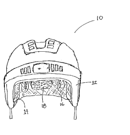
Protective device 10 is shown in Figs. 1 and 2 as comprising outer shell 12,
liner 14, and a means associated with the liner for enabling controlled
displacement
of preselected regions of the liner upon various degrees of impact to the
outer shell.
Although a protective hockey helmet will be described in detail, it will be
understood
that the protective device is not limited to use in association with helmets,
or even
sports.
Outer shell 12 preferably comprises of a high strength plastic material that
is
specifically designed to absorb an impact imparted thereto -- although other
conventionally used helmet shell materials are likewise contemplated -- and
has inner
surface 13. It is also contemplated, however, that the outer shell may
comprise any
covering, including but not limited to other polymers, plastics, ceramics or
even soft
materials such as fabric or clothing, to accommodate different applications.
As is shown in Fig. 3, liner 14 is attached to interior surface 13 of outer
shell
12 by the hook and loop attachment means marketed under the trade name VELCRO.
Though VELCRO is preferred, other attachment or adhesive means such as snaps,
8
CA 02274513 1999-06-07
screws, rivets, glue, paste or tape are also contemplated for use in joining
liner 14 to
outer shell 12.
Liner 14 and associated controlled displacement means are also shown in Fig.
3 as comprising first material 16 and second material 18. First material 16 is
fabricated from a material capable of absorbing and dissipating higher degrees
of
impact imparted upon outer shell 12, relative to the impact absorbing and
dissipating
characteristics of second material 18. Specifically, first material 16 is
capable of
absorbing and dissipating a single relatively high impact imparted on the
outer shell.
In a preferred embodiment, first material 16 is fabricated at least partially
from
polypropylene. However, other materials such as polystyrene, polyeurothane, or
other
relatively high density polymers are capable of use in the current invention.
Conversely, second material 18 is fabricated from a material capable of
absorbing and dissipating lower degrees of impact imparted upon outer shell
12,
relative to the impact absorbing and dissipating characteristics of first
material 16. In
particular, second material is capable of effectively absorbing and
dissipating repetitive
impact imparted upon the outer shell. Preferably, second material 18 is
fabricated at
least partially from vinyl nitrite, however, other relatively low density
polymers are
suitable for use with the current invention.
Together, first material 16 and second material 18 act in combination to
effectively and controllably absorb, displace, and dissipate varying degrees
and ranges
of impact imparted on outer shell 12.
9
CA 02274513 1999-06-07
First material 16, also shown in Figs. 4-10, has a bottom surface 20, a top
surface 22, and a thickness 24. Top surface 22 of first material 16 is
positioned
adjacent to interior surface 13 of outer shell 12. At least one hole 25
extends through
the thickness 24 of the first material 16, although a series of holes 25 are
preferred.
In a preferred embodiment, there are two different types of holes, plug holes
25 and
ventilation holes 26. Plug holes 25 receive plugs 19 fabricated from the
second
material 18 (hereinafter referred to as second materials plugs), while
ventilation holes
26 remain open and are aligned with ventilation holes 45 in the outer shell
12.
Alignment of ventilation holes 26 in the first material 18 with ventilation
holes 45 in
the outer shell 12 facilitates air flow through the helmet 1 1, to, in turn,
cool a
wearer's head.
Second material 18, shown in Fig. 4, also has a bottom surface 30, a top
surface 32, and a thickness 34. Second material plugs 19 are positioned in
plug holes
25 and secured by an interference fit such that top surface 32 of second
material 18
is also positioned adjacent to interior surface 13 of outer shell 12. However,
bottom
surface 30 of second material 18 extends further away from the interior
surface of
outer shell 12 than bottom surface 20 of first material 16. Accordingly, the
configuration of first and second materials results in second material
thickness 34 that
is greater than first material thickness 24. Although not shown, additional
securement
can be accomplished with adhesive.
Such a configuration creates the improved ability to controllably absorb,
CA 02274513 1999-06-07
displace, and dissipate a varying range of impacts over an extended period of
time.
As is shown in Figs. 11 and 12, impact imparted upon outer shell 12 of the
helmet
first forces compression of second material 18, which has a bottom surface
extending
further from interior surface 13 of outer shell 12, and maintains primary
contact with
a wearer's head. If the impact is of a relatively low degree (Fig. 1 1 ), the
second
material absorbs and displaces the impact such that bottom surface 30 of
second
material 18 merely returns to its original position in preparation for
additional impacts.
If, however, an impact forces compression of the second material such that the
distance between interior surface 13 of outer shell 12 and bottom surface 30
of
second material 18 is equal to or less than the distance between interior
surface 13
of outer shell 12 and bottom surface 20 of first material 16, first material
16
operatively and effectively absorbs, displaces, and dissipates further
compression
resulting from the impact upon the outer shell (see Fig. 12).
Furthermore, such a configuration also places the head of a wearer of
protective
helmet in primary contact with the second material, a softer and more user-
friendly
material. Accordingly, the wearer experiences a more comfortable fit.
Referring now to Figs. 4-6, the interference fit of second material plugs 19
into
first material plug holes 25 comprises of the plug holes having a desired
shape and an
inner peripheral surface 28, which, in turn, has a circumference (it will be
understood
that the term circumference, though generally associated with a substantially
circular
shape, also applies to the perimeter of a plug hole which is not necessarily
11
CA 02274513 1999-06-07
substantially circular in shape -- as the plug holes of the current invention
are not
limited to any specific shape). In one preferred embodiment of this invention
(see Fig.
4), the first material plug hole is configured so as to have a ridge 27
associated with
at least a portion of inner peripheral surface 28.
Each first material plug hole 25 is associated with a corresponding second
material plug 19, with each plug 19 having a shape and an outer peripheral
surface 38,
which, in turn, has an outer circumference (likewise, the same interpretation
of the
term circumference will be understood to apply in the case of the plugs). Also
in the
present embodiment, second material plug 19 is configured so as to have a
groove 37
in at least a portion of outer peripheral surface 38. Groove 37 is configured
for
alignment with ridge 27 of a corresponding first material plug hole 25. Upon
insertion
of second material plug 19 into first material plug hole 25, groove 37
operatively
cooperates with corresponding ridge 27 to form an interference fit. No
additional
attachment means or adhesion is required to maintain the fit. However, it is
certainly
contemplated that an adhesive means may be used between the second material
plug
and the first material plug hole for additional adhesion.
Such an interference fit with a groove configuration in the second material
plugs
enables maximization of the surface area of bottom surface 30 of second
material 18.
Accordingly, maximum contact is achieved between the second material and a
wearer's head, thus allowing for a helmet with increased comfort and increased
impact
protection.
12
CA 02274513 1999-06-07
In another embodiment, shown in Fig. 5, second material plugs 19 are
configured so as to have a ridge 50 in at least a portion of outer peripheral
surface 38.
Conversely, the corresponding first material plug holes 25 are configured so
as to have
a groove 52 in at least a portion of inner peripheral surface 28. Like the
above
preferred embodiment, insertion of the second material plug with a ridged
outer
peripheral surface into the corresponding first material plug hole with a
grooved inner
peripheral surface provides a similar secure interference fit.
In yet another embodiment, shown in Fig. 6, the interference fit comprises
second material plugs 19 that are larger in at least one circumferential
dimension than
the corresponding first material plug holes 25, while also having shapes that
are
substantially similar to the shapes of the corresponding first material plug
holes.
Accordingly, the size differential in at least one circumferential dimension
of the plug
and hole shapes forces the second material plug to be operatively compressed
and
oriented before insertion into the corresponding first material plug hole.
Therefore,
after insertion of the compressed second material plug into the first material
plug hole,
the second material plug undergoes a slight expansion, in turn forcing at
least a portion
of outer peripheral surface 38 of the second material plug into substantial
and gripping
contact with inner peripheral surface 28 of the first material plug hole.
Again, an
independent adhesive is not required to hold the plug in place during helmet
use,
although one may certainly be used.
Aside from the impact absorbing and dissipating advantages described
13
CA 02274513 1999-06-07
hereinabove, the interference fit has additional advantages such as ease of
assembly
and replaceability of parts. The second material plugs simply "pop" into the
first
material plug holes with very little effort, and can be removed with ease as
well. This
replaceability, in turn, allows the wearer of the helmet to replace the plugs
for any
number of different reasons, including fit, comfort, or wear and tear.
. Also in a preferred embodiment, shown in Figs. 4-10, first material plug
holes
25 and corresponding second material plugs 19 are strategically located so as
to
provide optimal impact absorption and dissipation, while at the same time
providing
optimal stabilization of and comfort for a wearer's head. Preferably, the plug
holes
and plugs are positioned so that bottom surfaces 30 of the second material
plugs
come into contact with critical portions -- such as the occipital, frontal,
parietal, and
temporal regions -- of the wearer's head.
In another embodiment, shown in Figs. 7-10, liner 14 may comprise of both a
front piece 40 and a back piece 42, which fit matingly together (see Fig. 8).
The two
pieces operatively come together and overlap along joinder line 60. This
overlapping
orientation allows the liner to effectively and controllably absorb and
displace impact
imparted on outer shell 12 in the area of joinder liner 60. Such a multiple
piece
construction allows for both greater ease and less expense in manufacturing
the liner.
14